
Bosch Rexroth IndraDrive Drive
Protection against contact with electrical parts and housings
Contact with parts conducting voltages above 50 volts can cause personal danger and electric shock. When operating components of the electric drive and control system, it is unavoidable that some parts of these components conduct dangerous voltage. High electrical voltage! Danger to life, risk of injury by electric shock or serious injury!
- Only qualified persons are allowed to operate, maintain and/or repair the components of the electric drive and control system.
- Follow the general installation and safety regulations when working on power installations.
- Before switching on, the equipment grounding conductor must have been permanently connected to all electric components in accordance with the connection diagram.
- Even for brief measurements or tests, operation is only allowed if the equipment grounding conductor has been permanently connected to the points of the components provided for this purpose.
- Before accessing electrical parts with voltage potentials higher than 50 V, you must disconnect electric components from the mains or from the power supply unit. Secure the electric component from reconnection.
- With electric components, observe the following aspects: Always wait 30 minutes after switching off power to allow live capacitors to discharge before accessing an electric component. Measure the electrical voltage of live parts before beginning to work to make sure that the equipment is safe to touch.
- Install the covers and guards provided for this purpose before switching on.
- Never touch any electrical connection points of the components while power is turned on.
- Do not remove or plug in connectors when the component has been powered.
- Under specific conditions, electric drive systems can be operated at mains protected by residual-current operated circuit-breakers sensitive to universal current (RCDs/RCMs).
- Secure built-in devices from penetrating foreign objects and water, as well as from direct contact, by providing an external housing, for example a control cabinet. High housing voltage and high leakage current! Danger to life, risk of injury by electric shock!
- Before switching on and before commissioning, ground or connect the components of the electric drive and control system to the equipment grounding conductor at the grounding points.
- Connect the equipment grounding conductor of the components of the electric drive and control system permanently to the main power supply at all times. The leakage current is greater than 3.5 mA.
- Establish an equipment grounding connection with a minimum cross section according to the table below. With an outer conductor cross section smaller than 10 mm2 (8 AWG), the alternative connection of two equipment grounding conductors is allowed, each having the same cross section as the outer conductors.
Cross section outer conductor Minimum cross section equipment grounding conductor Leakage current ≥ 3.5 mA
1 equipment grounding conductor 2 equipment grounding conductors 1.5 mm2 (16 AWG) 10 mm2 (8 AWG)
2 × 1.5 mm2 (16 AWG) 2.5 mm2 (14 AWG) 2 × 2.5 mm2 (14 AWG) 4 mm2 (12 AWG) 2 × 4 mm2 (12 AWG) 6 mm2 (10 AWG) 2 × 6 mm2 (10 AWG) 10 mm2 (8 AWG) – 16 mm2 (6 AWG) 16 mm2 (6 AWG)
– 25 mm2 (4 AWG) – 35 mm2 (2 AWG) – 50 mm2 (1/0 AWG) 25 mm2 (4 AWG) – 70 mm2 (2/0 AWG) 35 mm2 (2 AWG) –
Battery safety
Batteries consist of active chemicals in a solid housing. Therefore, improper handling can cause injury or property damage. Risk of injury by improper handling!
- Do not attempt to reactivate low batteries by heating or other methods (risk of explosion and cauterization).
- Do not attempt to recharge the batteries as this may cause leakage or explosion.
- Do not throw batteries into open flames.
- Do not dismantle batteries.
- When replacing the battery/batteries, do not damage the electrical parts installed in the devices.
- Only use the battery types specified for the product.
Appropriate use
This product may only be used for the mentioned applications under the specified application, ambient and operating conditions. This product is exclusively intended for use in machines and systems in an industrial environment. This is to be understood as applications according to IEC 60204-1 “Safety of machinery, Electric equipment of machines” and NFPA 79 “Electrical Standard for Industrial Machinery”.
Ratings and dimensions
Data
| Description | Symbol | Unit | HCS01.1E –W0003- _-02 | HCS01.1E –W0006- _-02 | HCS01.1E –W0009- _-02 | HCS01.1E –W0013- _-02 | HCS01.1E –W0018- _-02 |
| Listing in accordance with UL standard | UL 508C | ||||||
| Listing in accordance with CSA standard | C22.2 No. 274-13 | ||||||
| UL files | E134201 | ||||||
| Pollution degree | 2 | ||||||
| Ambient temperature with nominal data | Tamas | °C | 40 | ||||
| Mass | m | kg | 1.30 | 2.10 | |||
| Device height1) | H | mm | 215 | 268 | |||
| Device depth2) | T | mm | 196 | ||||
| Device width3) | B | mm | 50 | 70 | |||
| Minimum distance on the top of the device4) | drop | mm | 90 | ||||
| Minimum distance on the bottom of the device5) | dot | mm | 90 | ||||
| Horizontal spacing on the device6) | dehorn | mm | 10 | 0 | |||
| Rated control voltage input7) | UN3 | V | 24 ±20% | ||||
| Rated power consumption control voltage input at UN38) | PN3 | W | 27 | 28 | 34 | ||
| Short circuit current rating | SCCR | Arms | 42000 | ||||
| Rated input voltage, power9) | ULN.nenn | V | 1 or 3 x AC 110…230 | ||||
| Tolerance rated input voltage ULN | % | ±10 | |||||
| Mains frequency | FLN | Hz | 50…60 | ||||
| Mains frequency tolerance | Hz | ±2 | |||||
| Rated input current | ILN | A | 1.8 or 0.6 | 2.8 or 1.2 | 5.0 or 2.3 | 8.3 or 4.5 | 12.8 or 9.6 |
| Branch circuit protection fuse10) | 2.5 or 1.0 | 3.5 or 2.0 | 7.0 or 3.0 | 12.0 or 5.0 | 17.5 or 15.0 | ||
| Required wire size in accordance with NFPA 79 and UL 508 A (in‐ ternal wiring);11) | ALN | AWG | AWG 14 | ||||
| Last modification: 2018-05-29 | |||||||
UL ratings and dimensions
| Description | Symbol | Unit | HCS01.1E –W0005- _-03 | HCS01.1E –W0008- _-03 | HCS01.1E –W0018- _-03 | HCS01.1E –W0028- _-03 | HCS01.1E –W0054- _-03 |
| Listing in accordance with UL standard | UL 508C | ||||||
| Listing in accordance with CSA standard | C22.2 No. 274-13 | ||||||
| UL files | E134201 | ||||||
| Pollution degree | 2 | ||||||
| Last modification: 2019-02-20 | |||||||
| Description | Symbol | Unit | HCS01.1E –W0005- _-03 | HCS01.1E –W0008- _-03 | HCS01.1E –W0018- _-03 | HCS01.1E –W0028- _-03 | HCS01.1E –W0054- _-03 |
| Ambient temperature with nominal data | Tamax | °C | 40 | ||||
| Mass | m | kg | 1.3 | 2.10 | 4.60 | ||
| Device height1) | H | mm | 215 | 268 | |||
| Device depth2) | T | mm | 196 | ||||
| Device width3) | B | mm | 50 | 70 | 130 | ||
| Minimum distance on the top of the device4) | drop | mm | 90 | ||||
| Minimum distance on the bottom of the device5) | adbot | mm | 90 | ||||
| Horizontal spacing on the device6) | dehorn | mm | 10 | 0 | |||
| Rated control voltage input7) | UN3 | V | 24 ±20% | ||||
| Rated power consumption control voltage input at UN38) | PN3 | W | 27 | 28 | 34 | 45 | |
| Short circuit current rating | SCCR | Arms | 42000 | ||||
| Rated input voltage, power9) | ULN_nenn | V | 3 x AC 200…500 | ||||
| Tolerance rated input voltage ULN | % | ±10 | |||||
| Mains frequency | FLN | Hz | 50…60 | ||||
| Mains frequency tolerance | Hz | ±2 | |||||
| Rated input current | ILN | A | 1.5 | 2.5 | 5.0 | 10.0 | 28.0 |
| Branch circuit protection fuse10) | 2 | 4 | 10 | 15 | 30 | ||
| Required wire size in accordance with NFPA 79 and UL 508 A (in‐ ternal wiring);11) | ALN | AWG | AWG 14 | AWG 10 | |||
| Field wiring material (material; conductor temperature; class) | Cu; 60/75 °C; 1 | ||||||
| Output voltage | Vought | V | 3 x AC 0…500 | ||||
| Output current | Out | A | 1.7 | 2.7 | 7.6 | 11.5 | 21.0 |
| Output frequency range12) | flout | Hz | 0…1600 | ||||
| Power dissipation at continuous current and continuous DC bus power respectively13) | Discount | W | 37.00 | 46.00 | 80.00 | 120.00 | 400.00 |
| Last modification: 2019-02-20 | |||||||
Distances
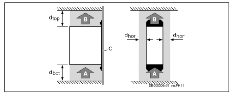
 A Air intake
- B Air outlet
- C Mounting surface in control cabinet
- drop Distance top
- dbot Distance bottom
- dhor Distance horizontal
Fig. 2-1: Air intake and air outlet at device
Dimensional Drawings
HCS01.1E-W0003/5/6/8/9/13 Standard mounting: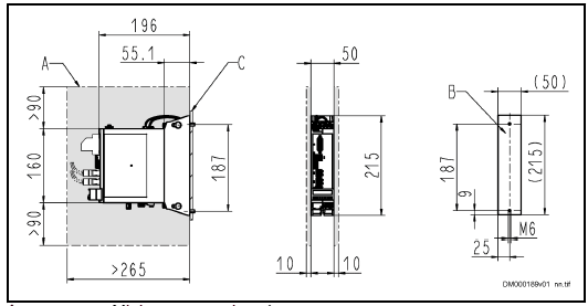
- A Minimum mounting clearance
- B Boring dimensions
- C Mounting surface
Fig. 2-2: Dimensional Drawing HCS01.1E-W0003/5/6/8/9/13 (Standard Mounting)
Left-hand or right-hand mounting: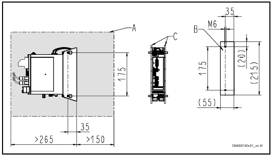
- A Minimum mounting clearance
- B Boring dimensions
- C Mounting surface
Fig. 2-3: Dimensional Drawing HCS01.1E-W0003/5/6/8/9/13 (Left-Hand or Right-Hand Mounting)
Ratings and dimensions
HCS01.1E-W0018/28 Standard mounting: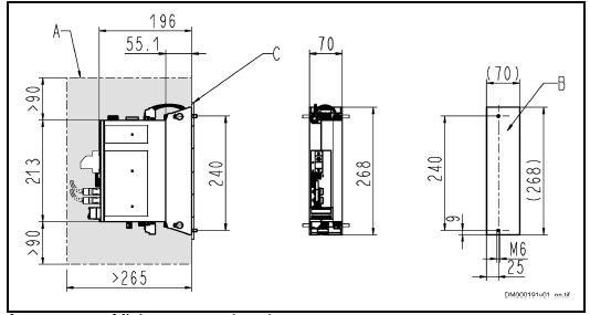
- A Minimum mounting clearance
- B Boring dimensions
- C Mounting surface
Fig. 2-4: Dimensional Drawing HCS01.1E-W0018/28 (Standard Mounting) Left-hand or right-hand mounting
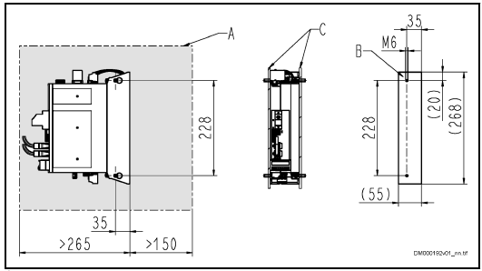
- A Minimum mounting clearance
- B Boring dimensions
- C Mounting surface
Fig. 2-5: Dimensional Drawing HCS01.1E-W0018/28 (Left-Hand or Right- Hand Mounting)
HCS01.1E-W0054 Standard mounting: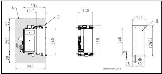
- A Minimum mounting clearance
- B Boring dimensions
- C Mounting surface
Fig. 2-6: Dimensional Drawing HCS01.1E-W0054 (Standard Mounting) Left-hand or right-hand mounting:
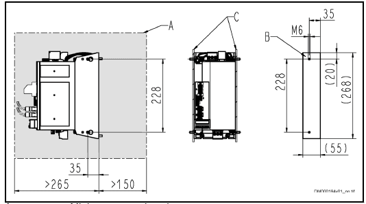
- A Minimum mounting clearance
- B Boring dimensions
- C Mounting surface
Fig. 2-7: Dimensional Drawing HCS01.1E-W0054 (Left-Hand or Right-Hand Mounting)
Documentations
Motors
| Title Rexroth IndraDyn … | Type of documentation | Document typecode1) DOK-MOTOR*-… | Material number R911… |
| A Asynchronous Motors MAD / MAF | Project Planning Manual | MAD/MAF****-PRXX-EN-P | 295781 |
| H Synchronous Kit Spindle Motors | Project Planning Manual | MBS-H******-PRXX-EN-P | 297895 |
| L Synchronous Linear Motors | Project Planning Manual | MLF********-PRXX-EN-P | 293635 |
| L Ironless Linear Motors MCL | Project Planning Manual | MCL********-PRXX-EN-P | 330592 |
| S Synchronous Motors MKE | Project Planning Manual | MKE*GEN2***-PRXX-EN-P | 297663 |
| S Synchronous Motors MSK | Project Planning Manual | MSK********-PRXX-EN-P | 296289 |
| S Synchronous Motors MSM | Data Sheet | MSM********-DAXX-EN-P | 329338 |
| S Synchronous Motors MS2N | Project Planning Manual | MS2N*******-PRXX-EN-P | 347583 |
| T Synchronous Torque Motors | Project Planning Manual | MBT********-PRXX-EN-P | 298798 |
Instructions for use
Overcurrent protection
Protect the components against overcurrent:
- Branch circuit protection has to be provided externally
- Dimension the branch circuit protection according to the data “Branch circuit protection fuse” (see Ratings and dimensions.
Connection
Connection diagram
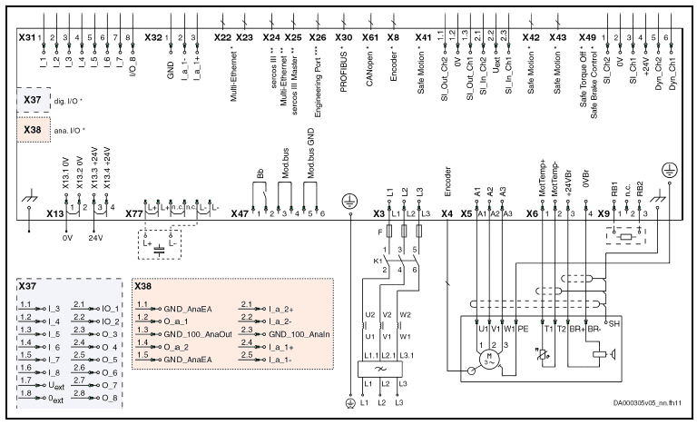
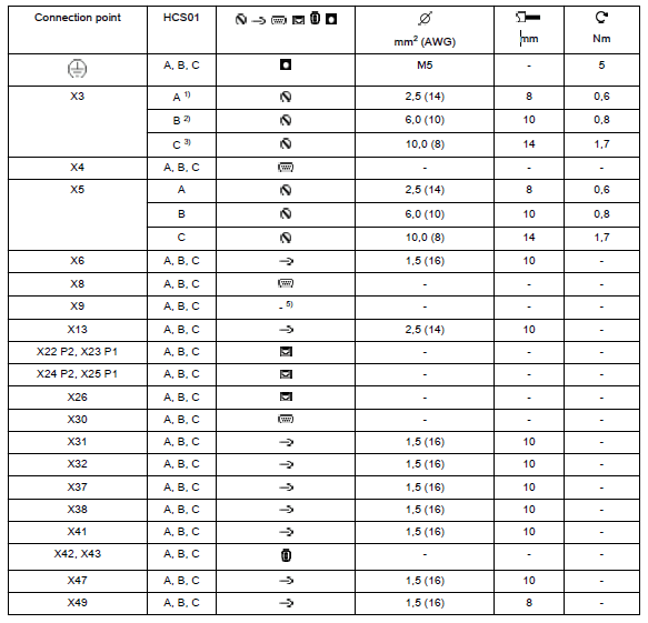
Connection Points


For more manuals by Bosch visit, ManualsLibraryy
Bosch Rexroth IndraDrive Drive-FAQs
What are the common fault codes for IndraDrive?
Fault codes include F9XXX, F8XXX, F7XXX, F4XXX, F3XXX, F2XXX, and EXXXX, which indicate issues like Fatal System Errors, Safety Technology Errors, and Warning Diagnostic Messages.
What does error code F2174 mean on a Rexroth IndraDrive?
Error code F2174 indicates a “Loss of Motor Encoder.” To resolve, clear the position status, set the absolute measure (home), and then cycle the power.
What is error code F8069 on a Rexroth servo drive?
F8069 signifies an issue with the internal ±15 Volt power supply in IndraDrive units.
What is error code F7E4?
Error code F7E4 indicates a basket re-engagement failure, often pointing to potential issues with shifter or actuator components.
What typically causes fault codes?
Fault codes are triggered by diagnostic trouble codes (DTCs), which identify malfunctions in systems. They are generated when onboard diagnostics detect anomalies.
How do you check fault codes on equipment?
Connect an OBD2 scanner to the device, turn it on, input required details, and press “scan” to retrieve the fault codes.
What does the fault code P03 mean?
P03 indicates system pressure is at 3 psi, which is insufficient for operation. This may require fixing or replacing the feed valve.
What does fault code 100-1 indicate?
Fault code 100-1 refers to “Engine Oil Pressure: Low,” which is a critical issue.
How can I test a servo motor?
Check the connections, verify the pin configuration matches the code, and ensure the servo receives adequate power, as these motors require significant energy.
What is the difference between a servo drive and a VFD?
Servo drives control permanent magnet motors and offer high torque due to rare Earth magnets in the rotor. VFDs, on the other hand, manage squirrel-cage motors for general applications.

 A Air intake