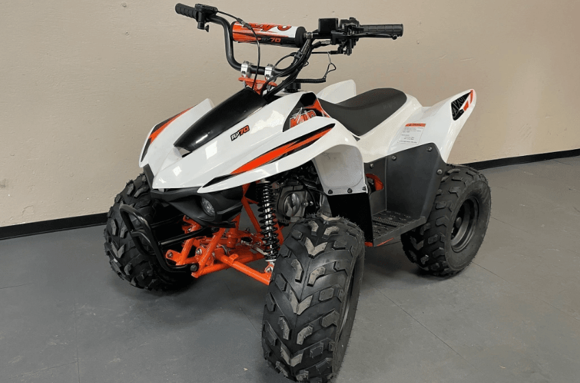
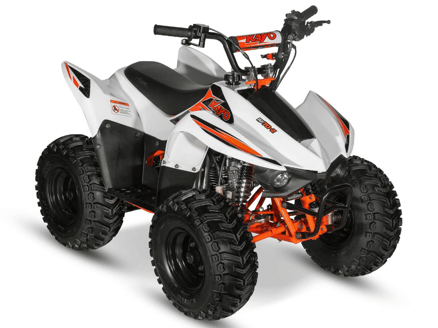
Kayo Motor AY702 Offroad Vehicle
Safety precautions
- Wear work clothes (coveralls), a hat, and safety boots suitable for the operation. In some conditions, safety glasses, dust masks, gloves, and other safety protective supplies are needed to protect you from injury.
- Do not run the engine in unventilated places.
- To prevent burns, do not touch the engine or exhaust until cooled.
- Battery solution (dilute sulfuric acid) is a strong corrosive agent; contact with the skin contact with eyes may cause blindness. If the battery solution accidentally touches clothes or skin, rinse immediately with clean, cold water. If the battery solution touches the eyes, please flush immediately with plenty of clean, cold water and get medical treatment as soon as possible. Batteries and battery solutions should be kept out of reach of children. Battery charging will produce flammable and explosive gases. If exposed to a source of fire or spark, there is a risk of explosion or fire. Please charge in well-ventilated places.
- Gasoline is flammable and explosive. Pay attention to sparks as well as open flames. Vaporized gasoline may explode if exposed to open flame or sparks. Please choose well-ventilated areas away from these hazards when refueling.
- Attention, the rear wheel, clutch, or other rotating parts and movable parts may clip hands and clothes during maintenance.
- Two or more people must constantly greet each other when operating to ensure safety.
Disassembly and installation instructions
- All the Parts, lubricants, oils, and fluids must be Kayo brand parts or Kayo recommends.
- During disassembly, please sort and separate out the parts and fasteners of each system to ensure that everything is put back together properly.
- Clean the vehicle or parts to be serviced before inspection.
- The Gasket, O-ring, piston pin baffle ring, cotter pin, and other one-time use parts must be replaced after disassembling.
- Snap rings can be deformed if opened too much during disassembly. DO NOT re-use deformed snap rings.
- After disassembly and inspection, clean the parts and blow the cleaning agent away with compressed air before measurement. Grease the moving surface before assembly.
- During disassembly, check all the necessary specifications and measure according to the directions in this manual. Make sure measurements and conditions are within specification.
- Bolts, nuts, screws, and other fasteners shall be pre-tightened and then tightened in accordance with the specified tightening torque in a diagonal sequence. From large to small, and from inside to outside.
- Inspect all rubber parts during disassembly and replace if necessary. In addition, as some rubber pieces are not resistant to corrosive materials, please keep them from contacting volatile oils, grease, or liquids.
- Smear or inject recommended grease in specific places as service manual.
- Use special tools for disassembly and installation.
- Ball bearings can be rotated with a finger to confirm whether the rotation is flexible and smooth. If there are problems as below, please replace the bearing.
- Bearings should be lubricated or packed with grease before assembly. Take note of the direction of installation when assembling. When installing an open or double-sided dustproof bearing, make the manufacturer’s logo and dimensions face outwards.
- Let the chamfered side face towards the force direction when installing the Snap-ring. Do not use the rings without elasticity. After assembly, rotate the Snap-ring to confirm that it is firmly installed in the slot.
- It’s important to check that all fastening parts are tightened and that functions are normal after assembling.
- Brake fluid and coolant can damage surfaces, painted parts, plastic parts, rubber parts, etc., do not let brake fluid contact these parts. If brake fluid contacts these parts, rinse and dilute with water immediately.
- When installing oil seals manufacturer’s mark and sizes face outward.
- When installing rubber hose parts, insert the rubber pipe into the fitting. If there is a hose clamp, install the hose clamp in the hose indentation. Replace rubber hoses if dried, cracked, or deformed.
- Keep the inner of the engine and brake hydraulic system away from dust and clay.
- Clean all gasket material from surfaces before installing new parts or reassembling.
- Do not bend the cable excessively. Kinked or damaged cables may cause poor response, and inner cables to fray and eventually break.
- When assembling any protective caps, covers, or boots, make sure they are seated correctly in the respective grooves.
Engine Break-in
There are a lot of relative motion components in the engine, such as the piston, piston ring, cylinder, and mutually meshing gear etc. It’s very important to have a standard break-in at the beginning of use. Break-in can help the moving parts adapt to each other, correct work, and form a smooth friction surface that can bear heavy loads; in this way, the engine will have excellent performance and reliability. Recommended break-in time is 20 hours, as follows:
0~~10 hours: Operate at no more than ½ throttle, keep gear changes and speed variances to a minimum. Do not operate for extended amounts of time with a fixed throttle position. Let the engine cool for 5 to 10 minutes after each hour of operation. Avoid quick acceleration. 0~~20 hours: Operate at no more than 3/4 throttle, do not operate for extended amounts of time with a fixed throttle position. Change gears and vary speeds as necessary. Let the engine cool for 5 to 10 minutes after each hour of operation. Avoid quick acceleration.
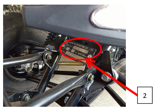
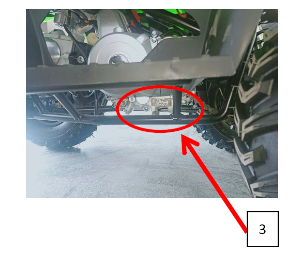
VIN Number
- VIN numbe

- Name Plate

- Engine number

Specifications, Model information

- Dimensions, Vehicle Specifications

- Engine parameters


- Frame

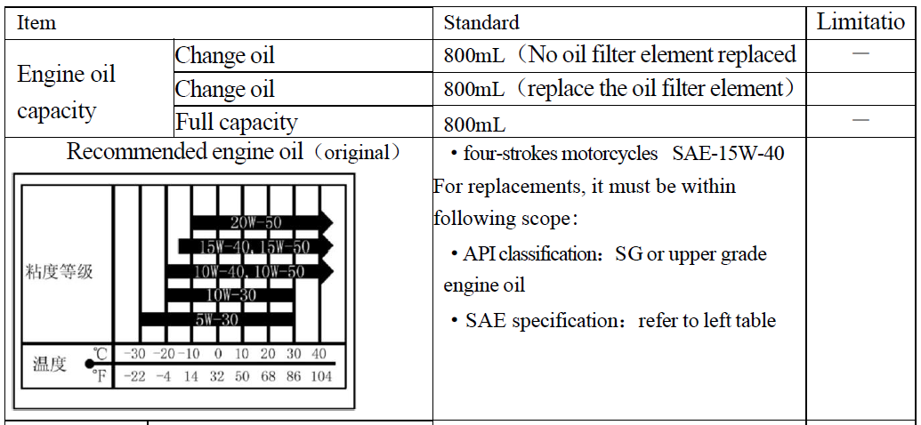
- Lubrication system


- Air intake system see engine section)
- Cooling device (without)
- Wheel (front and rear wheels)

- Brake system

- Ignition device

- Light / Instrument / Switch

- Valve mechanism + cylinder cover see engine section)
- Cylinder + piston + piston ring + crank connecting link see engine section)
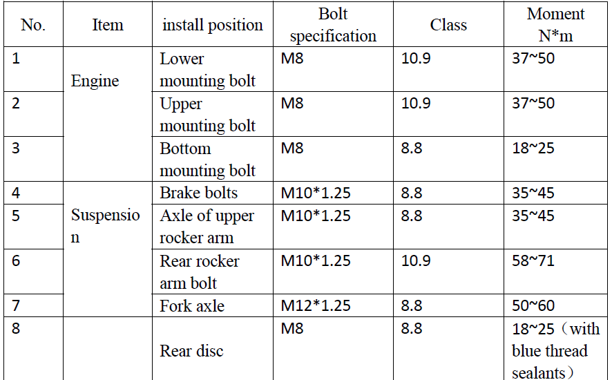
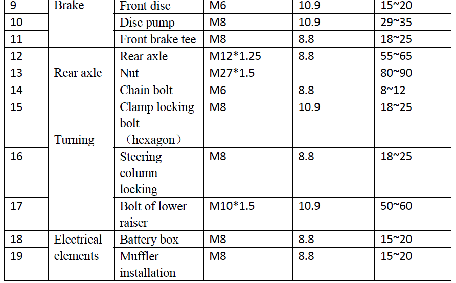
Fastener Torque Specifications
- Torque Specifications chart


- Tightening moment at specified position – engine(see engine section)
- Engine service tool(see engine section)
- Engine special tool(see engine section)
lubricating grease and sealant
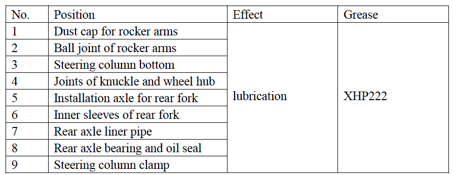
Note: Please coat the inside of the handlebar grip with grip glue before installing.
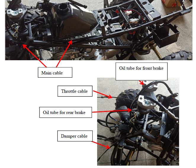
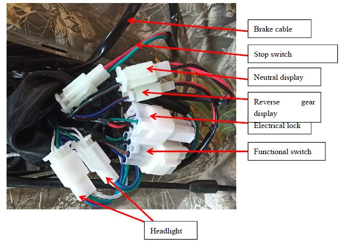
Wiring diagram of cable, hosepipe, and inhaul cable

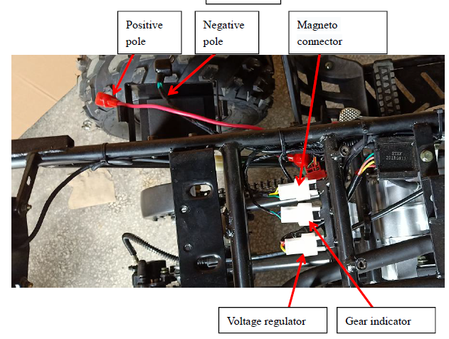


Maintenance cautions
Operation cautions
When replacing plastic parts, please install new warning labels, stickers, and riveted tags on the new plastics.
This chapter is about dismounting the body plastics. Pipe, inhaul cable should be equipped according to the wiring diagram of the cable, hosepipe, and inhaul cable.
Installation torque
- M8 bolt:18~~25N*m
- TM6 bolt:7\~11 N*m
- M6\* bolt:8~~12 N\*m
Hood
Disassembly
- Remove the bolts 1 and 2.
- Push down and gently pull the hood forward to remove. (Be careful as the tabs are easy to break)

Installation
In reverse order of disassembly. Locate tabs into slots and push to lock into place, then install bolts 1 and 2.
Handlebar
Disassembly
- Cut off power first. (Disconnect battery)
- Cut plastic ties first, then pluck the functional switch, stop switch, and brake cable plug in sequence.
- Loosen the fixed bolt from the brake bar with a tool and remove the rear brake bar.
- Remove the front brake bar as the same as the rear brake bar.
- Pull the damper cable as the picture shows, then remove it.
- Remove the bolt from the accelerator cap to remove the throttle cable.
- Dismount the fixed bolt, then the lower riser, remove the handlebar at last.

Installation
In reverse order from disassembly, then check if it is installed well.
- After installation, check the flame-out switch connector, function switch connector, brake connector, etc., in case of misconnection or looseness.
- Check if the dumper cable and throttle cable are in the right position.
- Front and rear brakes are in the right position; the wiring way refers to the vehicle wiring diagram.
Seat
Disassembly
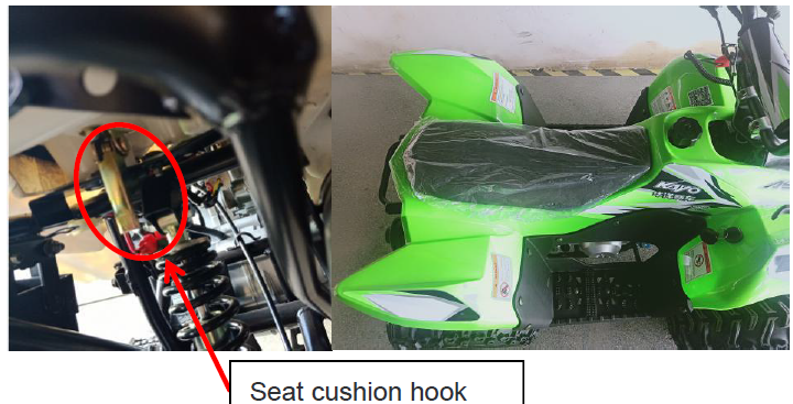
- Press the back of the seat cushion meanwhile opening the seat cushion hook.
- Lift the seat cushion tail and pull the seat cushion back.

Installation
Take it back in reverse order from disassembly. Check if the seat is installed in place and firm.
Front Bumper
Disassembly
- Disassemble the mounting bolt in order.
- Remove the front guard.

Installation
Take it back in reverse order from disassembly. If the mounting bolt or nut is broken, replace it with the same specification in time.
Plastic Body
Disassembly
- Disconnect all necessary electrical connectors.
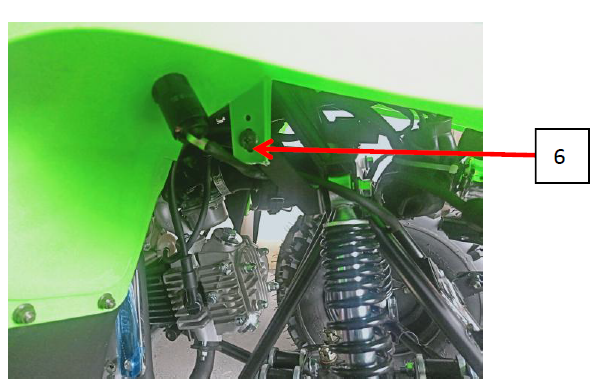
- Disassemble plastic parts fixing bolts1/2,3/4,5/6,7/8,9/10 in order. note (2/4/6/8/10 on the other side)
- Twist the oil cap and remove the plastic parts.


Note: remove the handlebars first before dismounting the plastic parts.
Installation
Install the plastic body in reverse order from disassembly. If the mounting bolt or nut is broken, replace it with the same specification in time. After installation, check the headlight connector, electric connector, reverse indicator connector, etc., in case of looseness or misconnect.)
Left and right plastic pedal
Disassembly of the right plastic part pedal
- Remove the foot mounting bolts 1 and 2.
- Take the right plastic pedal.

Installation
Take it back in reverse order from disassembly.
Maintenance information
- Do not run the engine in unventilated places, because the exhaust contains carbon monoxide (CO) and other toxic components.
- To prevent burns, don’t touch the engine or exhaust until it has cooled down., Please wear long-sleeved work clothes and gloves.
- Gasoline is flammable and explosive. Pay attention to sparks as well as open flames. Vaporized gasoline may explode if exposed to open flame or sparks. Please refuel in well-ventilated areas.
- Being careful of the drive system and rotating parts, keep fingers, loose clothing, and hair away from these parts.
Note: Keep the vehicle in a flat and stable place.
Maintenance period
Engine maintenance is a regular periodic work, due at certain time intervals for engine maintenance. Keeping up on standard maintenance will increase the lifespan and reliability of the components. The following is the AY70 engine maintenance period table.
Note: the contents in the table are based on normal conditions; if the bike is ridden in dusty, muddy, or wet areas, maintenance should be performed more often and as needed.
Steering column and brake system
Keep the vehicle in a steady place and hold the handlebars firmly as shown in the picture to check if it’s shaking.
If there is a shaking, check if it’s caused by the steering column or other parts, and then repair. If it’s caused by the steering column, fasten the lock nut on the steering column, or you can also disassemble the steering column. Keep the vehicle in a steady place and turn the handlebars slowly to check if the movement is smooth.
If it is hard to turn, check the cable, hose, and wire routing. If there is no problem, check the steering rods and connecting points for damage.
Front brake pump assembly
Check the fluid level at the sight glass on the master cylinder. If the brake is below the lower limit, stop using the vehicle immediately and inspect for leaks at the master cylinder, hoses, fittings, and connections. If fluid is low, remove the top of the master cylinder and add DOT4 brake fluid to the limit position.
- When adding brake fluid, do not mix it with dust and water.
- In order to prevent chemical changes, please choose the specified brand of brake fluid.
- As brake fluid will damage the plastic and rubber surfaces, please do not splash it on the parts.
Front brake disc and brake pads〈wear of brake block〉
- The brake pads, calipers, and discs are normal wear and tear items.
Check or replace the brake disc.
- Check the surface of the brake disc; if it is worn, damaged, bent, or grooved, replace it.
- If the disc thickness is less than 3.0mm, replace it.
- Check or replace brake pads〈wear of brake block〉
- Check the minimum thickness of the block. If it’s less than 1.5mm, replace it.
- Check for damage, cracks, and uneven wear. Replace the pad set if out of specification.
Wheel
With the ATV on a jack of atv lift. Lift the front wheels off the ground. Push and pull the wheel in and out as shown in the diagram. If there is movement, check torques on the hub, steering shafts, and spindles. If there is still movement, check the bearings, ball joints, and a-arm bushings. Replace if worn or damaged.
Front wheel size
On a level surface with handlebars straight, check the front wheel toe-in. The front wheel relative to the forward direction of the vehicle is: A in front and B behind the wheel. If not in this range, adjust the steering rod, adjust the wheel toe-in to 4\~10mm, and lock into place. After the adjustment of the front toe-in size, drive the vehicle slowly until you can control the direction.
Tyre pressure
Check the tyre pressure with a tire pressure gauge. (pressure range: 4~6PSI).
Tire tread
Check Tire tread; if the tread is less than 3mm, replace it. The inspection of the rear wheel is the same as the front wheel.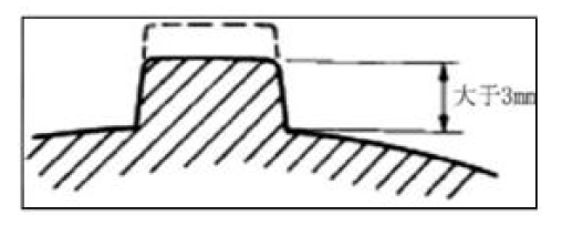
Suspension system
Keep the vehicle in a horizontal position and compress up and down several times according to the pictures. If there is shaking or an abnormal sound, check whether there is oil leakage in the shock absorber, and whether there is damage or loosening in the fastening parts.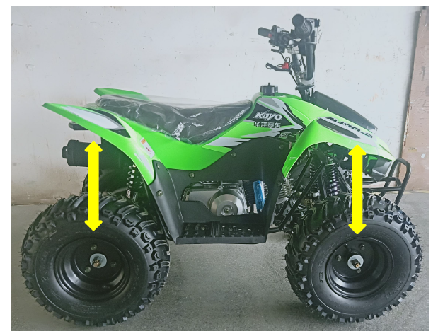
Throttle check
Check the free stroke of the throttle button. Press the accelerator several times as shown in the diagram, and check the freeplay of the thumb throttle. Under normal circumstances, there is no sticky phenomenon of the accelerator naturally.
Free play: 3\~5mm.
Adjust the throttle free play if out of specification.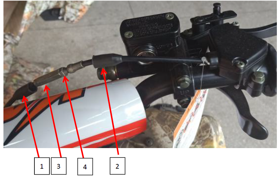
Remove the sleeve for 1/2, adjust the regulator 3, then turn the throttle to normal free stroke. Tighten nut 4, and install the sleeve back. If the above method is useless, replace a new throttle cable. Speed limiting device adjustment (The EPA state is not suitable). A speed limit device is used to restrict throttle opening. Inspect the thread length limit of the speed limit screw. Thread length a=25mm. Adjustment: Loosen the lock nut, then adjust it with a Phillips screwdriver.
Selection of front and rear shock absorbers
The front brake is adjustable. The rear brake can be adjusted from 1 to 5. The factory default state is gear 3.
Adjustment:
- By an absorber adjusting wrench (crescent).
- Turn left, the absorber gets soft, and right it will get hard.

Maintenance information
Precautions
- Before performing maintenance, please make sure that the engine is not running, the battery is disconnected, and that the heated parts have cooled, to avoid injury.
- Do not damage the frame, engine body, bolts, and cables during maintenance.
- In order to protect the engine frame, please wrap the engine before operating.
- When the engine is removed, the corresponding containers should be prepared to receive coolant, oil, and fuel oil for environmental protection, and the coolant and oil should be supplemented as required during installation.
- The engine does not need to be removed for the following operations.
-oil pump
-carburetor, air filter
-cylinder head cover, start motor, cylinder head, cylinder block, camshaft
-left cover, AC magneto
-piston, piston ring, piston pin - Remove the engine in the following operations.
-Crankshaft, main, and counter shaft
Fuel system
Gasoline is flammable and explosive. Pay attention to sparks and open flames. Vaporized gasoline may explode if exposed to open flame or sparks. Please choose well-ventilated areas away from these hazards when refueling or working on the fuel system and its related components.
Fuel tank removal
Remove the plastic body parts, remove fuel lines from the tank and fuel valve, then remove the tank mounting bolts and tank.
Air intake system
Disassembly
Loosen the air filter clamp and the exhaust pipe to remove the air filter.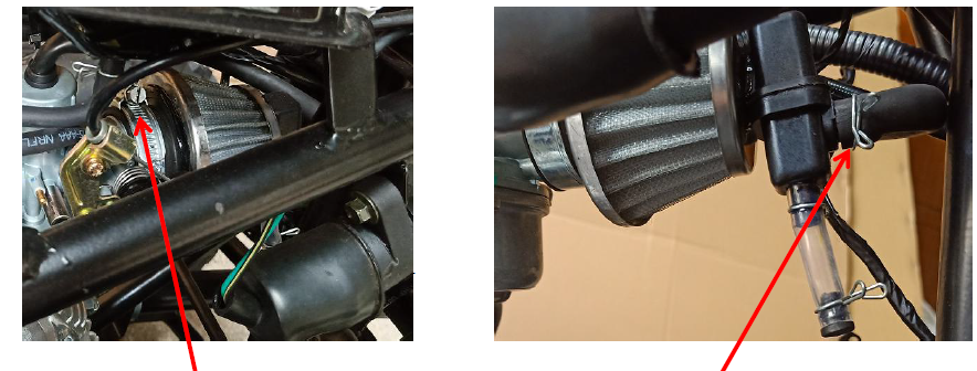
Installation
Installation shall be in the reverse order of removal. Make hose clamp is in the groove and any vacuum lines are hooked up correctly.
Exhaust system
Disassembly
Disassemble the clamp between the muffler and exhaust head pipe, then remove the muffler mounting bolt to remove the muffler.
Remove the self-locking nut 3 between the exhaust mouth and the exhaust pipe, then remove the exhaust pipe.
Installation
Installation shall be in the reverse order of removal. Note that if the exhaust pipe seal pad 4, graphite sleeve 5 for muffler mounting, and locking nut are damaged, replace them at once.
Disassembly and installation of engine
- Remove the engine side cover, then remove the chain.
- Remove the ground lead, gear indicator cable, magneto cable, start motor cable, exhaust pipe, ignition coil cap, and gearshift.


- Remove the power bolts, lug, and bolt of the engine bottom.

- Remove the engine from the right side of the vehicle. Installation shall be in the reverse order of removal.
For More Details Visit WWW.KAYOMOTO.COM.
For More Manuals By Kayo Motor, Visit ManualsLibraryy.
Kayo Motor AY702 Offroad Vehicle-FAQs.
How do I start the Kayo Fox ATV?
Ensure the fuel valve is ON.
Set the engine stop switch to “RUN”.
Engage the parking brake (if equipped).
Turn the ignition key or press the electric start button.
If cold, use the choke before starting.
How much oil does a Kayo 180cc ATV take?
The Kayo Bull 180cc requires 0.8L of air-cooled motorcycle oil with clutch additives.
How do I charge the Kayo ATV battery?
Disconnect the battery (negative terminal first).
Clean the terminals.
Connect a 12V battery charger.
Charge until full (green light on charger).
Reconnect (positive first, then negative).
How much oil does a 4-stroke dirt bike need?
Most 4-stroke dirt bikes require ~1.1L of oil. Use 10W-50 synthetic oil for optimal performance.
What is the top speed of the Kayo Fox 70?
The Kayo Fox 70cc is governed at 15 mph for safety (youth-rated).
How do I activate Kayo Sports on my ATV?
Kayo Sports is a streaming service—not related to the ATV. For ATV operation, refer to the owner’s manual.
How do I start an ATV for the first time?
Check fuel & oil levels.
Turn fuel valve ON.
Set engine stop switch to RUN.
Use choke if cold.
Start with key/button.
Can I jump-start a dead ATV battery?
Yes, but:
Use a 12V jumper pack or another ATV.
Connect red (+) first, then black (–).
Avoid revving the engine during jump-start.
What voltage should I use to charge the battery?
Use a 12V charger for ATV batteries. AGM batteries require a smart charger to avoid damage.

