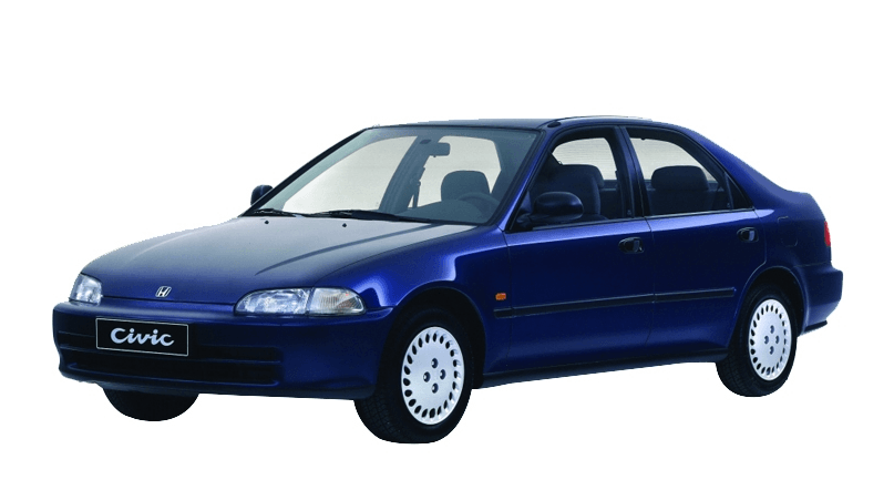
Honda Civic 1995 Car
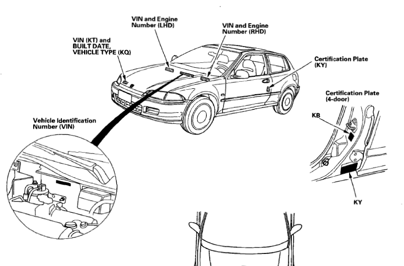
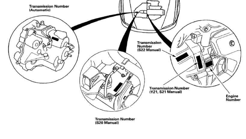
Identification Number Locations
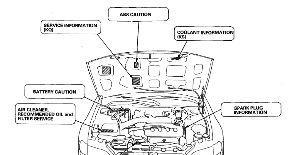
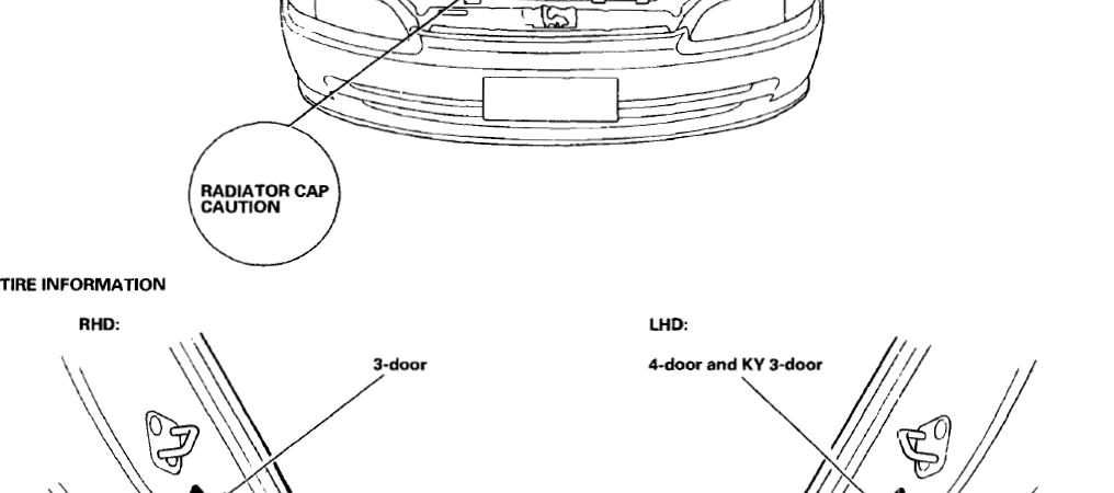
Warning/Caution Label Locations
SRS AIRBAG SYSTEM TYPE-II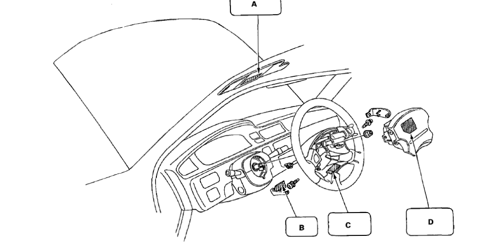
A: DRIVER INFORMATION (SUNVISOR) European models
ALWAYS WEAR YOUR SEAT BELT
- THIS CAR IS EQUIPPED WITH A DRIVER AIRBAG AS A SUPPLEMENTAL RESTRAINT SYSTEM (S.R.S.).
- IT IS DESIGNED TO SUPPLEMENT THE SEATBELT.
- IF YOUR SRS INDICATOR LIGHTS WHILE DRIVING, SEE YOUR AUTHORIZED HONDA DEALER.
A: DRIVER INFORMATION (SUNVISOR) except European models
ALWAYS WEAR YOUR SEAT BELT
- THIS CAR IS EQUIPPED WITH A DRIVER AIRBAG AS A SUPPLEMENTAL RESTRAINT SYSTEM (SRS).
- IT IS DESIGNED TO SUPPLEMENT THE SEAT BELT.
- IF YOUR SRS INDICATOR LIGHTS WHILE DRIVING, SEE YOUR AUTHORIZED HONDA DEALER.
B: MAINTENANCE LID CAUTION
BEFORE MAINTENANCE, SWITCH OFF THE IGNITION.
C: MONITOR NOTICE
REFER TO SERVICE MANUAL FOR DETAILED INSTRUCTIONS.
D: BODY COVER CAUTION
- REFER TO THE SERVICE (SHOP) MANUAL.
E: SRS WARNING (HOOD) LHD model
THIS VEHICLE IS EQUIPPED WITH. A DRIVER AIRBAG A.S A SUPPLEMENTAL RESTRAINT SYSTEM. (SRS)
ALL S.R.S. ELECTRICAL WIRING AI\ID CONNECTORS AF: E COLORED YELLOW. DO NOT USE ELECTRICAL TEST EQUIPMENT ON THESE CIRCUITS. TAMPERING WITH OR DISCONNECTING THE S.R.S. WIRING COULD RESULT IN ACCIDENTAL FIRING OF THE INFLATOR OR MAKE THE SYSTEM INOPERATIVE,
WHICH MAY RESULT IN SERIOUS INJURY.
E: SRS WARNING (HOOD) RHD model
SUPPLEMENTAL RESTRAINT SYSTEM (SRS) THIS VEHICLE IS EQUIPPED WITH A DRIVER SIDE AIRBAG.
ALL SRS ELECTRICAL WIRING AND CONNECTORS ARE COLORED YELLOW. TAMPERING WITH, DISCONNECTING, OR USING ELECTRICAL TEST EQUIPMENT ON THE SRS WIRING CAN MAKE THE SYSTEM INOPERATIVE OR CAUSE ACCIDENTAL FIRING OF THE INFLATOR.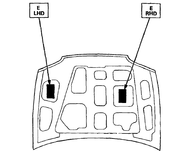
SRS AIRBAG SYSTEM TYPE-III
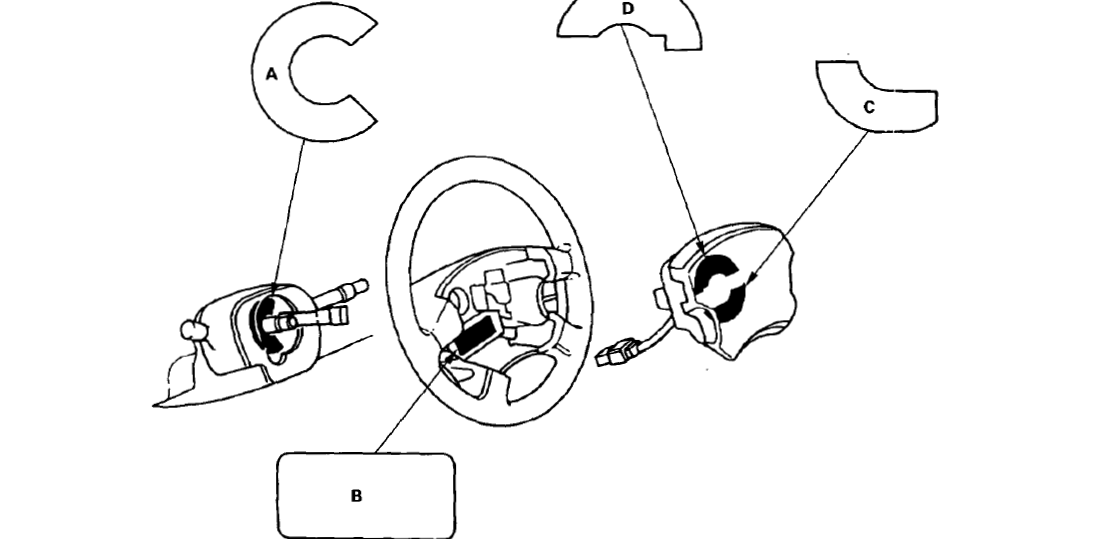
A: CABLE REAL CAUTION A
REFER TO THE SERVICE (SHOP) MANUAL FOR DETAILED INSTRUCTIONS. POUR LES INSTRUCTIONS DETAILLES, SE REPORTER AU MANUEL DE REPARATIONS
B: STEERING WHEEL NOTICE
IMPROPER STEERING WHEEL REMOVAL OR INSTALLATION CAN DAMAGE SRS COMPONENTS. FOLLOW SERVICE MANUAL INSTRUCTIONS CAREFULLY.
C: DRIVER MODULE WARNING
THE AIRBAG INFLATOR IS l: EXPLOSIVE AND, IF ACCIDENTALLY DEPLOYED. CAN SERIOUSLY HURT OR
KILL YOU.
- DO NOT USE ELECTRICAL TEST EQUIPMENT OR PROBING DEVICES. THEY CAN CAUSE ACCIDENTS. DEPLOYMENT.
- NO SERVICEABLE PARTS INSIDE. DO NOT DISASSEMBLE.
- PLACE AIRBAG UPRIGHT WHERE REMOVED.
- FOLLOW SERVICE (SHOP) Mt1NUAL INSTRUCTIONS CAREFULLY.
D: DRIVER MODULE DANGER
EXPLOSIVE/FLAMMABLE CONTACT WITH ACID, WATER, OR HEAVY METALS SUCH AS COPPER, LEAD, OR MERCURY, MAY PRODUCE HARMFUL AND IRRITATING GASES OR EXPLOSIVE COMPOUNDS. STORAGE TEMPERATURES MUST NOT EXCEED 200°F (100°C). FOR PROPER HANDLING, STORAGE AND DISPOSAL PROCEDURES, REFER TO THE HONDA SERVICE (SHOP) MANUAL, SRS SUPPLEMENT.
POISON CONTAINS POISONOUS SODIUM AZIDE AND POTASSIUM NITRATE. FIRST AID IF CONTENTS ARE SWALLOWED, INDUCE VOMITING. FOR EYE CONTACT, FLUSH EYES WITH WATER FOR 15 MINUTES. IF GASES (FROM ACID OR WATER CONTACT) ARE INHALED, SEEK FRESH AIR. IN EVERY CASE, GET PROMPT MEDICAL ATTENTION. KEEP OUT OF REACH OF CHILDREN
E: SRS WARNING (HOOD)
SUPPLEMENTAL RESTRAINT SYSTEM (SRSJ THIS VEHICLE IS EQUIPPED WITH A DRIVER AND FRONT
SEAT PASSENGER AIRBAG. ALL SRS ELECTRICAL WIRING AND CONNECTORS ARE COLORED YELLOW.
TAMPERING WITH, DISCONNECTING, OR USING ELECTRICAL TEST EQUIPMENT ON THE SRS WIRING
CAN MAKE THE SYSTEM INOPERATIVE OR CAUSE ACCIDENTAL FIRING OF THE INFLATOR.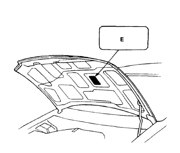
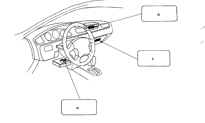
F: GLOVE BOX INFORMATION
AIRBAG INFORMATION SUPPLEMENTAL RESTRAINT SYSTEM (SRS)
- THE SRS MUST BE INSPECTED TEN YEARS AFTER IT IS INSTALLED. THE DATE OF INSTALLATION IS
SHOWN ON THE CERTIFICATION PLATE, LOCATED ON THE DRIVER’S DOOR JAMB. - DIAGNOSTIC CHECKS AND REPLACEMENT OF SRS COMPONENTS MUST BE DONE BY AUTHORIZED PERSONNEL DEALER.
- SEE YOUR OWNER’S MANUAL FOR ADDITIONAL SRS INFORMATION
G: FRONT SEAT PASSENGER AIRBAG MODULE DANGER
CONTACT WITH ACID, WATER, OR HEAVY METALS SUCH AS COPPER, LEAD, OR MERCURY MAY PRODUCE HARMFUL AND IRRITATING GASES OR EXPLOSIVE COMPOUNDS. STORAGE TEMPERATURE MUST NOT EXCEED 200°F (100°CJ. FOR PROPER HANDLING, STORAGE, AND DISPOSAL PROCEDURES, REFER TO SERVICE (SHOP) MANUAL, SRS SUPPLEMENT.
POISON CONTAINS POISONOUS SODIUM AZIDE AND POTASSIUM NITRATE. FIRST AID IF CONTENTS ARE SWALLOWED, INDUCE VOMITING. FOR EYE CONTACT, FLUSH EYES WITH WATER FOR 15 MINUTES. IF GASES (FROM ACID OR WATER CONTACT) ARE INHALED, SEEK FRESH AIR. IN EVERY CASE, GET PROMPT MEDICAL ATTENTION. KEEP OUT OF REACH OF CHILDREN
H: MONITOR NOTICE
- NO SERVICEABLE PARTS INSIDE.
- REFER TO SERVICE (SHOP) MANUAL FOR DETAILED INSTRUCTIONS.


Body Specifications
2-door Hatchback: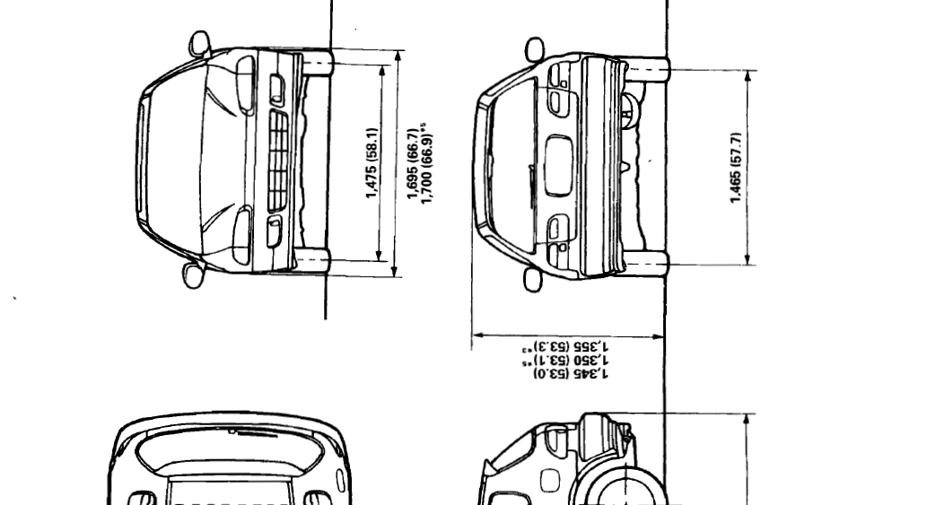
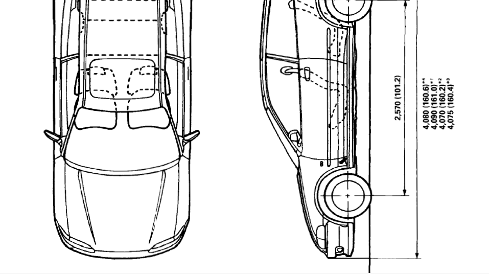
4-door Sedan: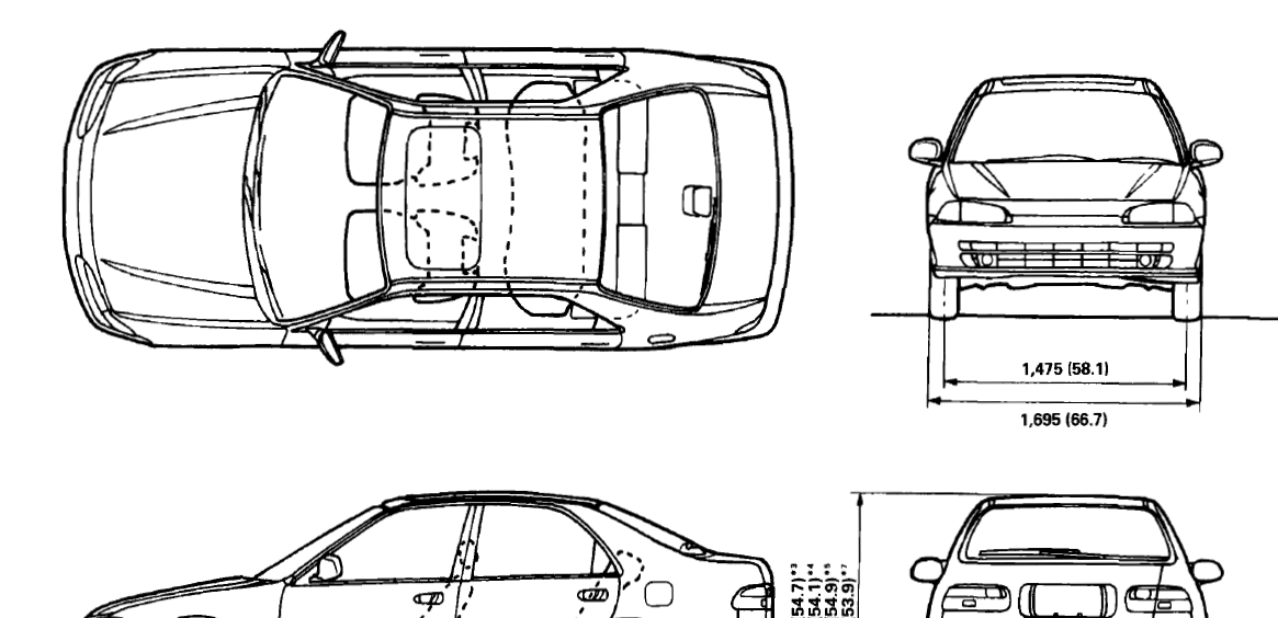

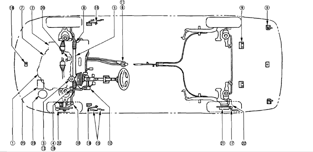
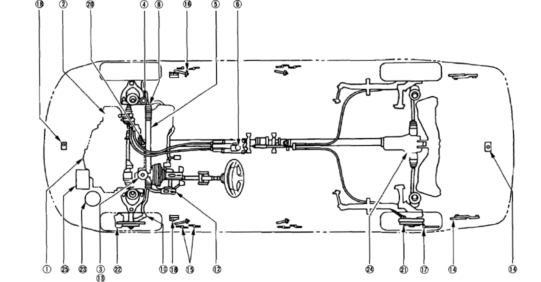
Lubrication Points
For the details of lubrication points and types of lubricants to be applied, refer to the Illustrated Index and various work procedures (such as Assembly/Reassembly, Replacement, Overhaul, Installation, etc.) contained in each section.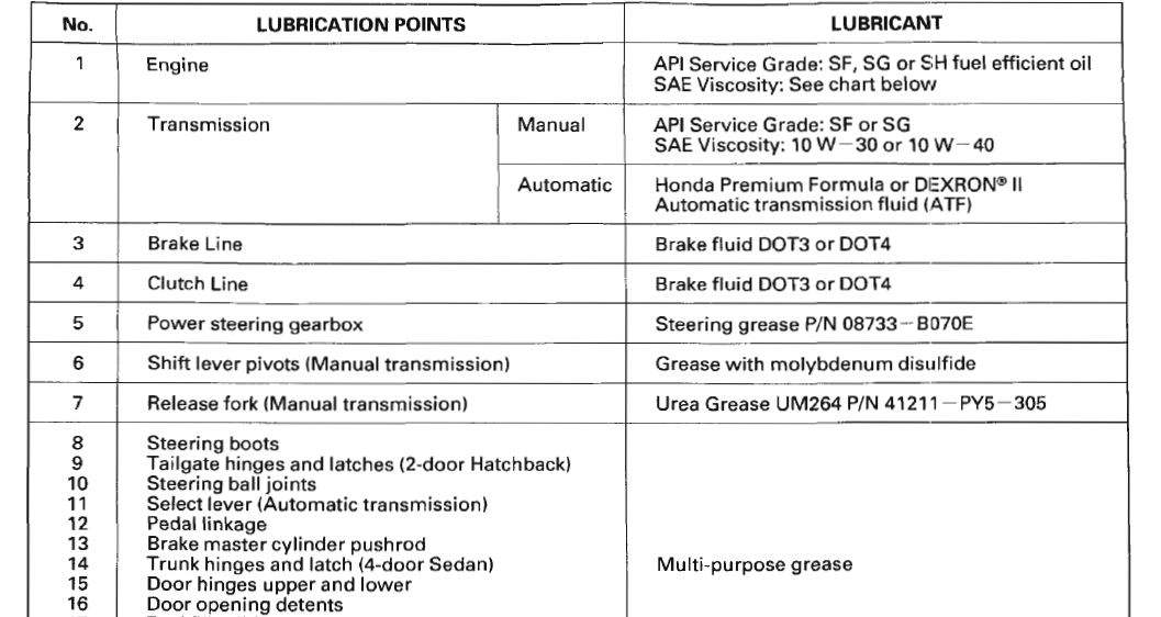

2-door Hatchback:
4-door Sedan and 4WD:
Carburetor Idle Speed/Mixture (D1382 engine
NOTE: Check the self-diagnosis indicator before making idle speed and mixture inspections
- Start the engine and warm it up to normal operating temperature (the cooling fan comes on twice).
- Connect a tachometer.
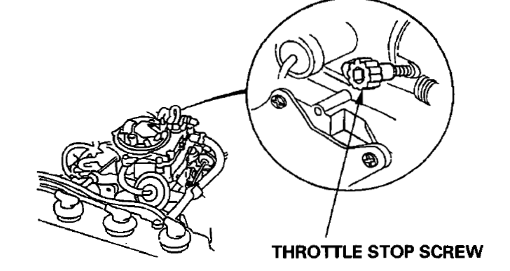
- Turn the ignition switch OFF. Restart the engine and hold the engine at idle for two minutes. And hold the engine at 3,000-3,500 rpm (min-1 ) for one minute. Check idle speed with the headlights, heater blower, rear window defogger, cooling fan, and air conditioner off. Idle speed should be: 900 ± 50 rpm (min•1). Adjust the idle speed, if necessary, by turning the throttle stop screw.

- Turn the ignition switch OFF. Restart the engine and hold the engine at idle for two minutes. And hold the engine at 3,000-3,500 rpm (min-1) for one minute. Check specification for idle CO with headlights, heater blower, rear window defogger, cooling fan, and air conditioner off. Specified CO% %: below 0.2. If idle CO is as specified, go to step 5. If not, refer to the base Shop Manual (P/N: 62SR300A 11-107), adjust the idle CO.
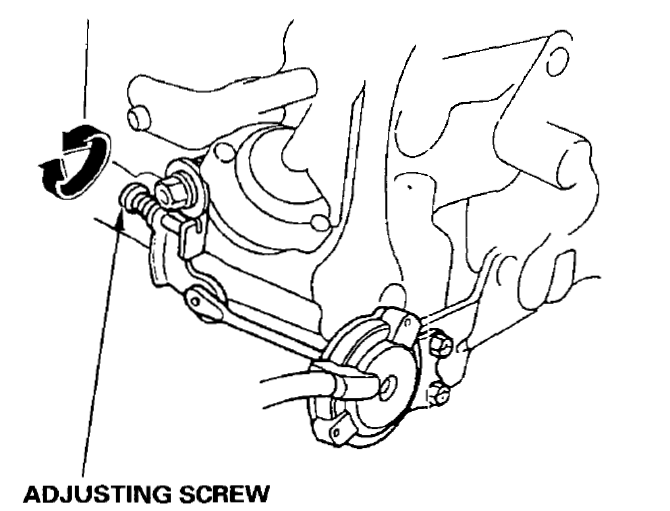
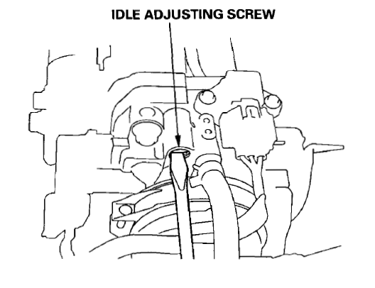
- If equipped with an air conditioner, check the idle speed with the A/Con. Idle speed should be: 900 ± 50 rpm (min-1). Adjust the idle speed, if necessary, by turning the adjusting screw.

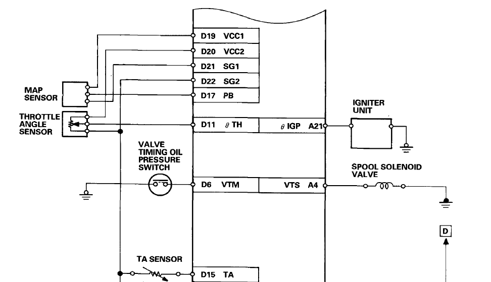
Component Locations Index (B16A3 engine)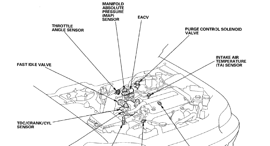
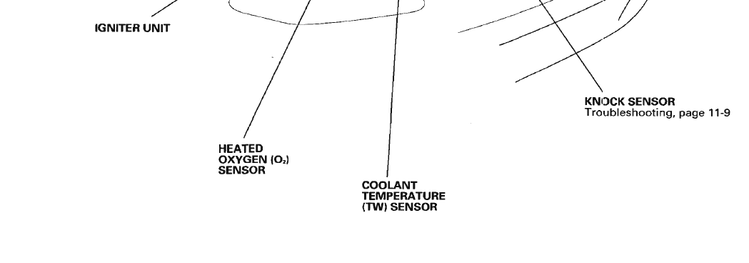
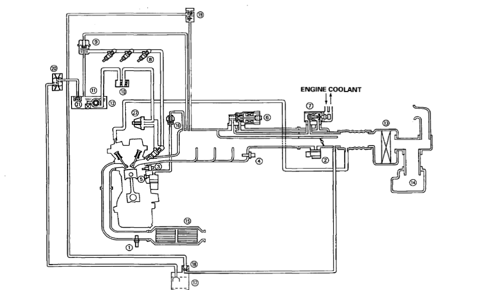
System Description Vacuum Connections (B16A3 engine)
- OXYGEN (0,) SENSOR
- MANIFOLD ABSOLUTE PRESSURE (MAP) SENSOR
- COOLANT TEMPERATURE (TW) SENSOR
- INTAKE AIR TEMPERATURE (TA) SENSOR
- KNOCK SENSOR
- FAST IDLE VALVE
- ELECTRONIC AIR CONTROL VALVE (EACV)
- FUEL INJECTOR
- PRESSURE REGULATOR
- FUEL FILTER
- FUEL PUMP
- FUEL TANK
- AIR CLEANER
- lJ RESONATOR
- CATALYTIC CONVERTER
- PCVVALVE
- CHARCOAL CANISTER
- PURGE CONTROL DIAPHRAGM VALVE
- PURGE CONTROL SOLENOID VALVE
- TWO-WAY VALVE
- FUELCUTVALVE

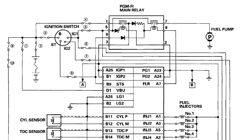
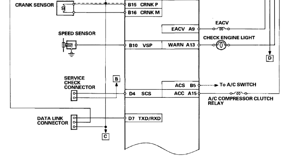
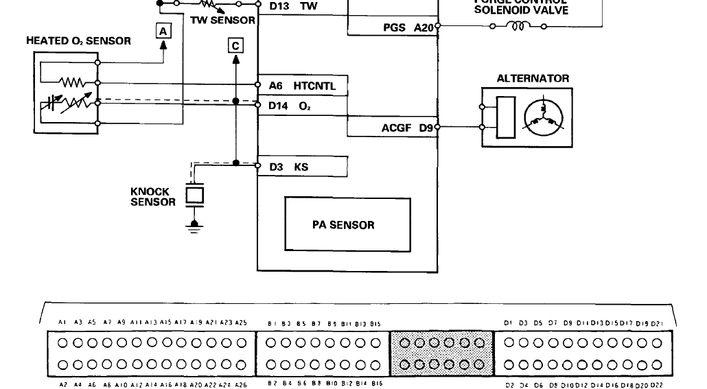
System Description Electrical Connections (B16A3 engine)
FUSES
- BACK UP (7.5 Al
- BATTERY (80 A)
- IG (50A)
- ECU (15A)
- ACG (SI (15 A)
- BACK-UP LIGHTS (10 A)
- REAR DEFROSTER RELAY HEATER MOTOR RELAY COOLING FAN IVIOTOR RELAY (7.5 A)
- STARTER SIGNAL (7.5 A)
- OPTION (50 Al
- INTERIOR LIGHT (7.5 A)
- UNDER-HOOD FUSE/RELAY BOX


Idle Control System Idle Speed Setting ( KM model )
Fuel Supply System
- Connect a tachometer.
- Start the engine. Hold the engine at 3,000 rpm (min-1) with no load (A/T in fNl or~ position, M/T in neutral) until the radiator comes on, then let it idle.
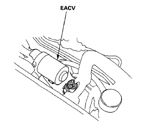
- Disconnect the 2P connector from the EACV.

- Start the engine with the accelerator pedal slightly depressed. Stabilize the engine speed at 1,000, then slowly release the pedal until the engine idles.
- Check idling in no-load conditions: headlights, blower fan, rear defogger, cooling fan, and air conditioner are not operating

- Turn the ignition switch OFF.
- Reconnect the 2P connector on the EACV, then remove BACK UP fuse in the under-hood fuse/relay box for 10 seconds to reset the ECU.
- Restart and idle the engine with no-load conditions for one minute, then check the idle ~ speed.
- Idle the engine for one minute with headlights (Low) ON and check the idle speed.
- Turn the headlights off. Idle the engine for one minute with the heater fan switch at High and the air conditioner on, then check the idle speed.
NOTE: If the idle speed is not within specification, see Idle Control System Troubleshooting Guide.
Fuel Lines
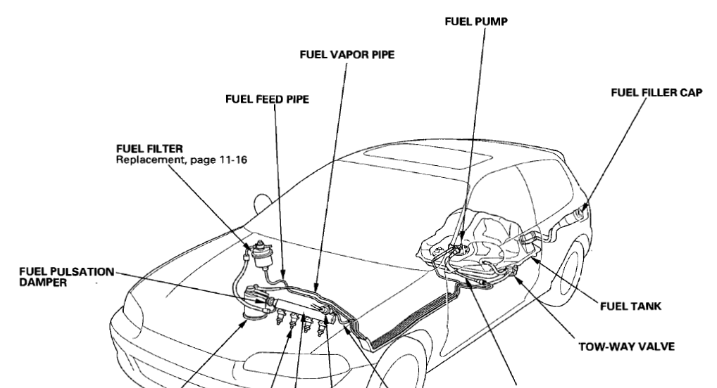

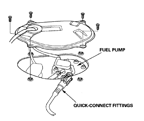
Fuel Tube/Quick-Connect Fittings (except D1587 /D1626 engines of KM/KH models)
Precautions
Do not smoke while working on the fuel system. Keep the open flame away from the work area. The fuel tube/quick-connect fittings assembly connects the in-tank fuel pump with the fuel feed pipe. For removing or installing the fuel pump and fuel tank, it is necessary to disconnect or connect the quick-connect fittings. Pay attention to the following:
- The fuel tube/quick-connect fittings assembly is not heat-resistant: be careful not to damage it during welding or other heat-generating procedures.
- The fuel tube/quick-connect fittings assembly is not acid-proof: do not touch it with a shop towel that was used for wiping away battery fluid. Replace the fuel tube/quick-connect fittings assembly if it came into contact with battery fluid or similar.
- When connecting or disconnecting the fuel tube/ quick-connect fittings assembly, be careful not to bend or twist it excessively. Replace it in case of damage.
- A disconnected quick-connect fitting can be reconnected, but the retainer on the mating pipe cannot be reused once it has been removed from the pipe. Replace the retainer when
- Replacing the fuel pump.
- Replacing the fuel feed pipe.
- It was removed from the pipe.
- It is damaged.

Disconnection
- Disconnect the battery negative cable.
- Relieve fuel pressure.
- Remove the fuel fill cap and relieve fuel pressure in the tank.
- Check the fuel quick-connect fittings for dirt, and clean if necessary.
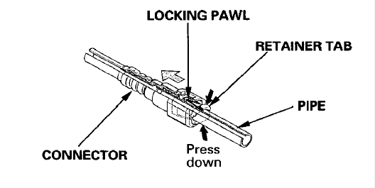
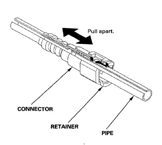
- Holding the connector with one hand and pressing down the retainer tabs with the other, pull the connector off.

NOTE:
- Be careful not to damage the pipe or other parts. Do not use tools.
- If the connector does not move, keep the retainer tabs pressed down, and alternately pull and push the connector until it comes off easily.
- Do not remove the retainer from the pipe; a removed retainer must be replaced with a new one.
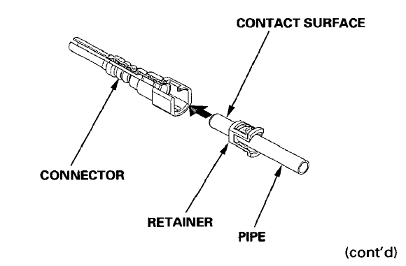
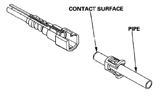
- Check the contact surface of the pipe for dirt and damage.
- If the surface is dirty, clean it.
- If the surface is rusty or damaged, replace the fuel pump or fuel feed pipe.

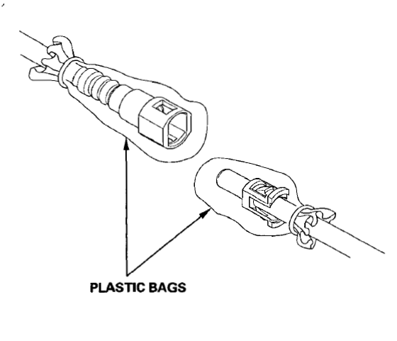
To prevent damage and the intrusion of foreign matter, cover the disconnected connector and pipe end with plastic bags or similar. NOTE: The retainer cannot be reused once it has been removed from the pipe. Replace the retainer when
- replacing the fuel pump.
- Replacing the fuel feed pipe.
- It was removed from the pipe.
- It is damaged.

Connection
- Check the pipe end for dirt and damage, and clean if necessary

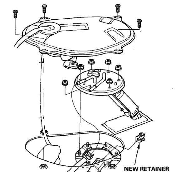
- Insert a new retainer into the connector if the retainer is damaged, or after
- Replacing the fuel pump.
- Replacing the fuel feed pipe.
- Removing the retainer from the pipe.

Before connecting a new fuel tube/quick-connect fitting assembly, remove the retainer from the mating pipe.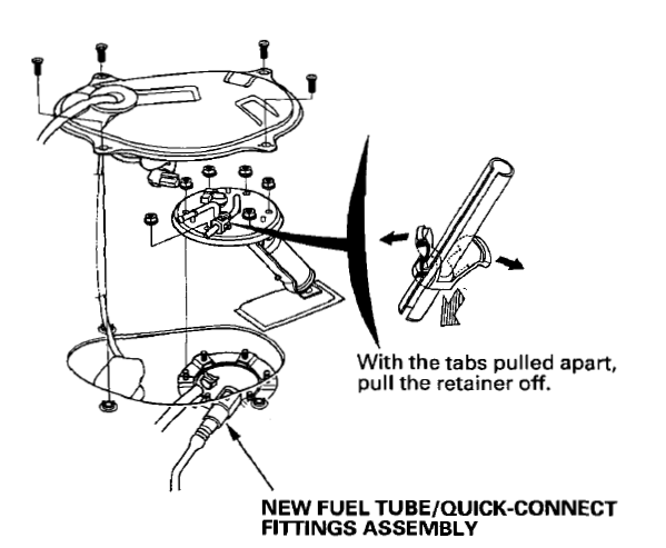
- Align the quick-connect fitting with the pipe, and align the retainer locking pawls with the connector grooves. Then press the quick-connect fitting onto the pipe until both retainer pawls lock with a clicking sound.
Connection with the new retainer.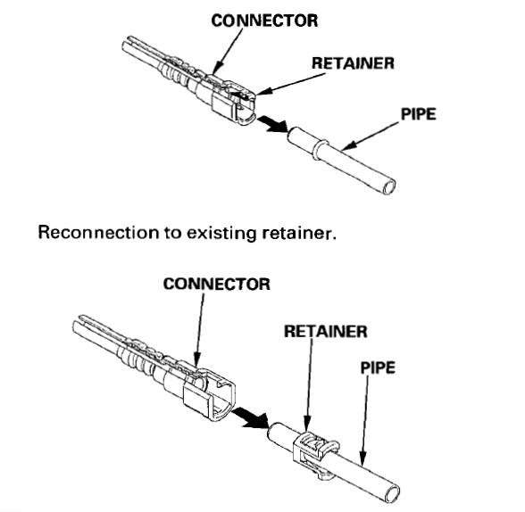
- Check visually and by pulling at the connector that the connection is secure and that the pawls are firmly locked into place.

- Reconnect the battery negative cable, and turn the ignition switch ON; the fuel pump will work for about two seconds, and fuel pressure will rise. Repeat two or three times, and check that there is no leakage in the fuel supply system
Replacement
The fuel filter should be replaced every 2 years or 40,000 km (24,000 miles), whichever comes first, or whenever the fuel pressure drops below the specified value [280-330 kPa, 2.8-3.3 kg/cm2, 40-47 psi with the fuel pressure regulator vacuum hose disconnected and pinched] after making sure that the fuel pump and the fuel pressure regulator are OK.
- Disconnect the negative battery cable from the battery negative terminal.
- Place a shop towel under and around the fuel filter.
- Relieve fuel pressure.
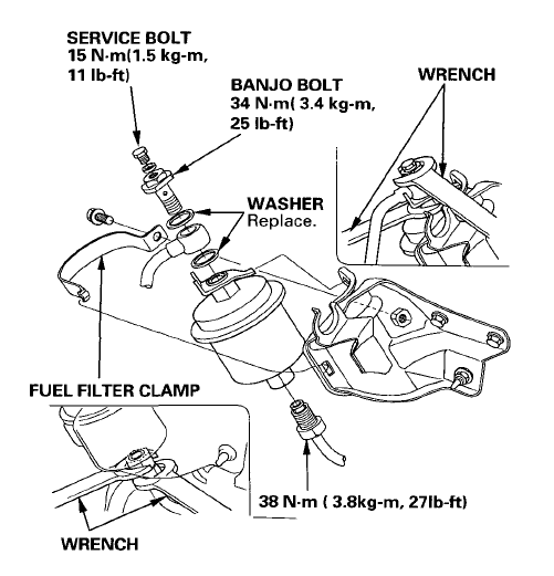
- Support the fuel filter with a wrench, as shown, then remove the banjo bolt and the fuel feed pipe from the fuel filter.
- Remove the fuel filter clamp and filter.
- When assembling, use new washers, as shown.

NOTE: Clean the flared joint of high-pressure hoses thoroughly before reconnecting them..
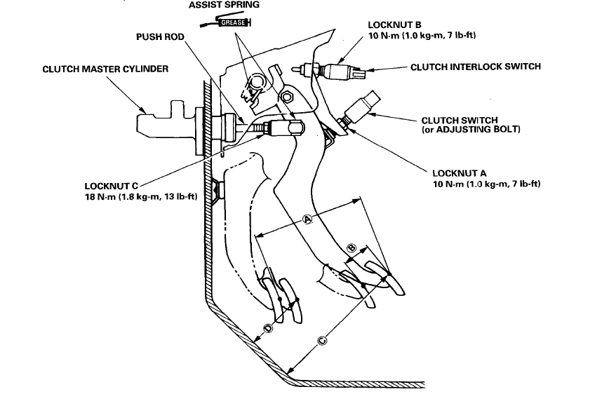
Clutch Pedal (With Clutch Interlock Switch)
Adjustment
NOTE:
- To check the clutch interlock switch and clutch switch, see section 23.
- The clutch is self-adjusting to compensate for wear.
CAUTION:
If there is no clearance between the master cylinder piston and push rod, the release bearing is held against the diaphragm spring, which can result in clutch slippage or other clutch problems.
- Loosen locknut A, and back off the clutch switch (or adjusting bolt) until it no longer touches the clutch pedal.
- Loosen locknut C, and turn the push rod in or out to get the specified stroke (@) and height (© ) at the clutch pedal.
- Tighten the locknut C.
- Thread in the clutch switch (or adjusting bolt) until it contacts the clutch pedal
- Turn the clutch switch (or adjusting bolt) an additional 3/4 to 1 full turn.
- Tighten locknut A.
- Loosen locknut B on the clutch interlock switch (with clutch interlock switch).
- Measure the clearance between the floor board and clutch pedal with the clutch pedal fully depressed.
- Release the clutch pedal 15 – 20 mm (0.59 – 0.79 in) from the fully depressed position and hold it there. Adjust the position of the clutch interlock switch so that the engine will start with the clutch pedal in this position.
- Thread the clutch interlock ~: with an additional 3/4 to 1 full turn.
- Tighten locknut B.

- STROKE at PEDAL): 130 – 140 mm (5.12 – 5.51 in)
- TOTAL CLUTCH PEDAL FREE PLAY)12 – 21 mm (0.47 – 0.83 in) including the pedal play 1 – 10 mm (0.04 0.37 in
- CLUTCH PEDAL HEIGHT: 164 mm (6.46 in) to the floor
- CLUTCH PEDAL DISENGAGEMENT HEIGHT: 83 mm (3.27 in) minimum to the floor
Countershaft Assembly Clearance Inspection
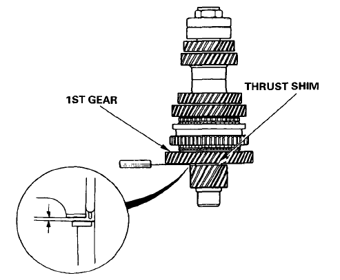
- Measure the clearance between the 1st gear and the thrust shim. Standard: 0.045 – 0.205 mm (0.0018-0.0082 in) Service Limit: 0.265 mm (0.0104 in).

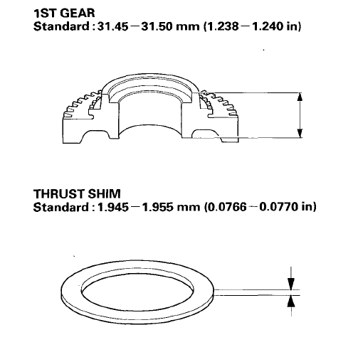
- If the clearance exceeds the service limit, measure the thicknesses of the 1st gear and thrust shim. 1STGEAR Standard:31.45-31.50 mm (1.238-1.240 in)

- If the thicknesses of the 1st gear and the thrust shim are less than the standard, replace them with a new one.
- If the thicknesses of the 1st gear and thrust shim are within the standard, replace the 1st/2nd synchro hub with a new one

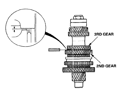
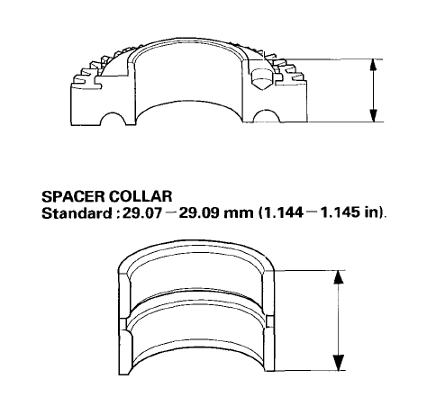
- Measure the clearance between the 2nd and 3rd gears. Standard: 0.07 – 0.14 mm (0.003-0.006 in) Service Limit: 0.20 mm (0.0013 in)
- If the clearance exceeds the service limit, measure the thicknesses of the 2nd gear and spacer collar. 2NDGEAR Standard:28.92 – 28.97 mm (1.139-1.141 in)

- If the thicknesses of the 2nd gear and spacer collar are less than the standard, replace,~ with a new one.
- If the thicknesses of the 2nd gear and spacer collar are within the standard, replace the 1st/2nd synchro hub with a new one.
Transmission Assembly Reassembly
Torque the reverse idler shaft bolt as shown.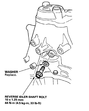
For More Manuals By Honda, Visit ManualsLibraryy.
Honda Civic 1995 Car-FAQs.
What is the fuel consumption of a 1995 Honda Civic?
The 1995 Honda Civic averages 7.2L/100km (around 32-33 MPG).
Does the 1995 Honda Civic come in a manual transmission?
Yes, the 1995 Civic was available with a manual transmission, though newer models (post-2025) have limited manual options.
How much horsepower does the 1995 Honda Civic have?
DX Sedan (4D): 102 HP
EX Sedan (4D): 125 HP
What are common issues with the 1995 Honda Civic?
Airbag light (faulty occupant position sensor)
Bad engine mounts (causing vibrations/rattles)
Shift control solenoid failure
Exhaust manifold/catalytic converter cracks
How big is the fuel tank in a 1995 Honda Civic?
The fuel tank capacity is 11.9 gallons (45 liters).
How do I start a 1995 Honda Civic with a key?
Insert the key into the ignition.
Turn clockwise until the engine starts.
Release the key once the engine is running.
Why won’t my 1995 Honda Civic start?
Common causes:
Dead battery
Faulty alternator
Failed starter motor
How do I jump-start a 1995 Honda Civic?
Connect red (+) clamp to the dead battery.
Connect the other red (+) clamp to the booster battery.
Attach black (-) clamp to a ground point (not the dead battery).
Start the working car, then the dead Civic.
How do I drive a manual 1995 Honda Civic?
Press the clutch and shift into 1st gear.
Slowly release the clutch while pressing the gas pedal.
Shift smoothly through gears as speed increases.
Is the 1995 Honda Civic fuel-efficient?
Yes, it’s one of the most fuel-efficient compact cars of its time, averaging 32-33 MPG.


