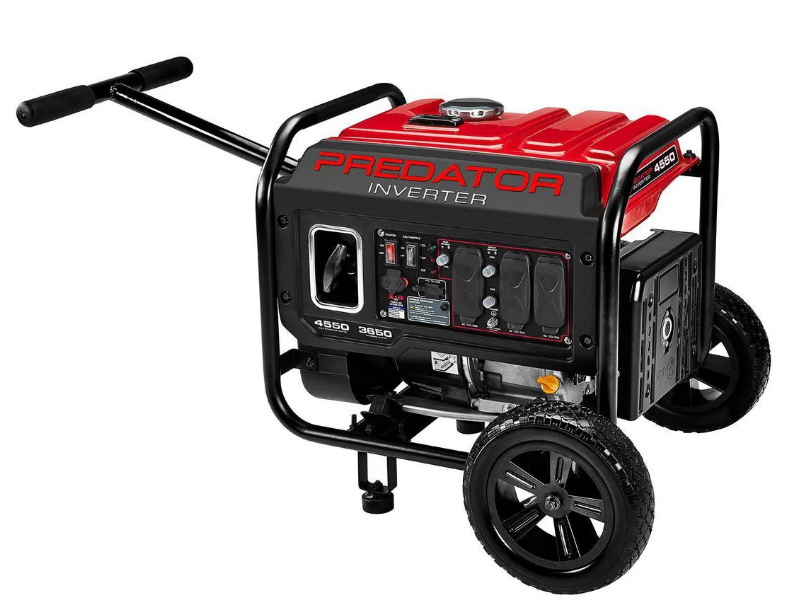
Predator 4550-Watts Portable Inverter Generator
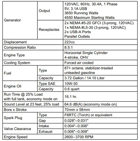
Specifications
Set Up
Grounding
The generator must be properly grounded in accordance with all relevant electrical codes and standards before operation. In many locations, local code will not require this generator to be grounded when used with cord and plug equipment plugged directly into the receptacles on the generator. However, your local regulations may require the generator to be grounded. Contact a licensed electrician or consult local authorities regarding local grounding requirements.
If grounding is required, have the unit grounded by a qualified electrician if you are not qualified to do so. General grounding instructions are as follows: Use one of the following as the grounding electrode: Pipe or conduit, minimum ¾ in. diameter, minimum 8 ft. long. If steel, it must have an anti-corrosion coating. Rod, stainless steel or copper- or zinc-coated steel, minimum 5/8 in. diameter, minimum 8 ft. long.
- Drive the electrode at least 8 ft. vertically into the ground.
- If a rock layer prevents vertical entry, drive at an angle not exceeding 45 degrees from vertical.
- If a rock layer prevents angled entry, bury the electrode in a horizontal trench at least 30 in. deep.
- The upper end of the electrode must be protected if above ground level.
- Connect a #6 AWG grounding wire (not included) from the grounding terminal on the generator control panel to the buried electrode.
For additional information on grounding methods, please see the National Electrical Code. Notice: There is a permanent conductor between the portable generator inverter module (neutral conductor) and the frame.
High Altitude Operation Above 3000 Feet
WARNING! To prevent serious injury from fire: follow instructions in a well-ventilated area away from ignition sources. If the engine is hot from use, shut the engine off and wait for it to cool before proceeding. Do not smoke.
NOTICE: Warranty is void if necessary adjustments are not made for high altitude use. At high altitudes, the engine’s carburetor, governor, and any other parts that control the fuel-air ratio will need to be adjusted by a qualified mechanic to allow efficient high-altitude use and to prevent damage to the engine and any other devices used with this product.
The fuel system on this engine may be influenced by operation at higher altitudes. Proper operation can be ensured by installing an altitude kit at altitudes higher than 3000 ft above sea level. At elevations above 8000 ft, the engine may experience decreased performance, even with the proper main jet. Operating this engine without the proper altitude kit installed may increase the engine’s emissions and decrease fuel economy and performance. The kit should be installed by a qualified mechanic.
Note: Not all generator models have a solenoid. Skip those steps if a solenoid is not present.
- Turn off the engine.
- Close the fuel valve.
- Place a bowl under the fuel cup to catch any spilled fuel.
- Unthread the screws holding the solenoid in place. CAUTION! The carburetor bowl may have gas in it, which will leak upon removing the solenoid/bolt.
- Disconnect the solenoid and solenoid seal from the bolt.
- Unthread the bolt holding the fuel cup.
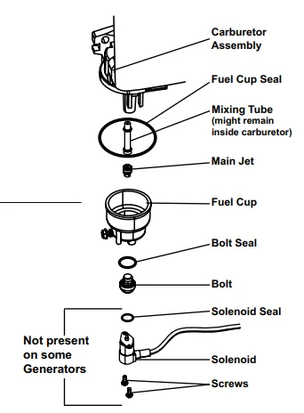
- Remove the bolt, bolt seal, fuel cup, fuel cup seal, and main jet from the body of the carburetor assembly. A carburetor screwdriver (not included) is needed to remove and install the main jet. Note: The mixing tube is held in place by the main jet and might fall out when it is removed. If it falls out, replace it in the same orientation before replacing the main jet.
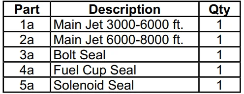
- Replace the main jet with the replacement main jet needed for your altitude range (part 1a or 2a). Note: The fuel cup seal and bolt seal may be damaged during removal and should be replaced with the new ones from the kit.
- Replace the fuel cup seal (4a), fuel cup, bolt seal (3a), and bolt. Tighten in place. NOTICE: Do not cross-thread the bolt when tightening. Finger-tighten first and then use a wrench to make sure the bolt is properly threaded.
- Replace the solenoid and solenoid seal (5a) and tighten in place with screws.
- Wipe up any spilled fuel and allow excess to evaporate before starting the engine. To prevent fire, do not start the engine while the smell of fuel hangs in the air.

High Altitude Kit Parts List – A
Components and Controls
Operation
Pre-Start Checks
Inspect the engine and generator, looking for damaged, loose, or missing parts before setup and starting. If any problems are found, do not use the generator until fixed properly.
Checking and Filling Engine Oil
NOTICE: The generator is shipped without engine oil. The engine’s crankcase MUST be filled with oil before first use. Your warranty is VOID if the engine’s crankcase is not properly filled with oil before first use and before each use thereafter. Before each use, check the oil level. The engine will not start with low or no engine oil.
- Make sure the engine is stopped and level.
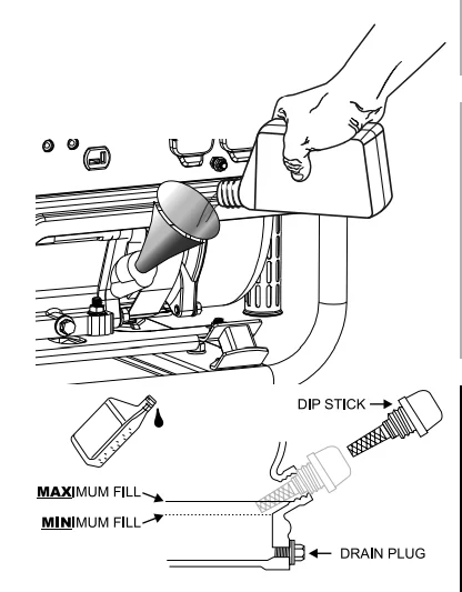
- Clean the top of the oil fill cap/dipstick and the area around it. Remove the cap/dipstick by turning it counterclockwise.
- Check the oil level. The oil level should be up to the edge of the hole as shown.
- As needed, add the appropriate type of oil until the oil level is at the proper level. SAE 10W-30 oil is recommended for general use.
- Thread the oil fill cap/dipstick back in clockwise.

NOTICE: Do not run the engine with too little oil. The engine will shut off if the engine oil level is too low.
Checking and Filling Fuel
![]() WARNING! To prevent serious injury from fire: fill the fuel tank in a well-ventilated area away from ignition sources. If the engine is hot from use, shut the engine off and wait for it to cool before adding fuel. Do not smoke.
WARNING! To prevent serious injury from fire: fill the fuel tank in a well-ventilated area away from ignition sources. If the engine is hot from use, shut the engine off and wait for it to cool before adding fuel. Do not smoke.
- Clean the fuel cap and the area around it.
- Unscrew and remove the fuel cap.
- Remove the strainer and remove any dirt and debris. Then replace the strainer
- If needed, fill the fuel tank to about 1 inch under the fill neck of the fuel tank with 87 octane or higher unleaded gasoline that has been treated with a fuel stabilizer additive. Follow the fuel stabilizer manufacturer’s recommendations for use.
- Replace the fuel cap.
- Wipe up any spilled fuel and allow excess to evaporate before starting the engine. To prevent fire, do not start the engine while the smell of fuel hangs in the air.
Starting the Engine
Before starting the Engine
- Inspect the generator and engine.
- Disconnect all electrical loads from the generator.
- Fill the engine with the proper amount and type of both stabilizer-treated unleaded gasoline and oil.
Manual Start
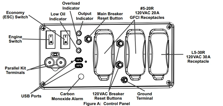
- Move the Economy (ESC) Switch to the OFF position.
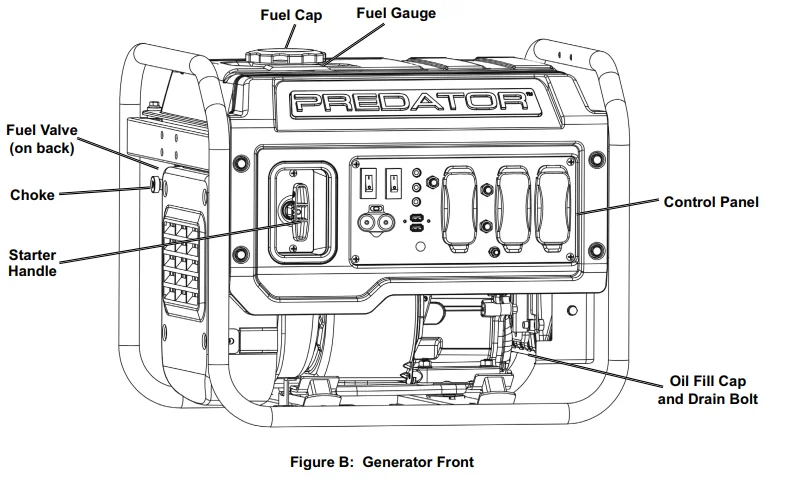
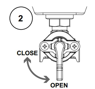
- Open the Fuel Valve on the back of the Generator under the Fuel Tank.

- Pull the Choke out to the START position.
- Turn the Engine Switch on.

- Grip the Starter Handle of the Engine loosely and pull it slowly several times to allow the gasoline to flow into the Engine’s carburetor. Then pull the Starter Handle gently until resistance is felt. Allow the Cable to retract fully and then pull it quickly. Repeat until the Engine starts. Do not let the Starter Handle snap back against the housing. Hold it as it recoils so it doesn’t hit the housing.
If the engine does not start:
- Check engine oil level. The engine will not start with low or no engine oil.
- Check spark arrestor cleanliness. The engine will not start if the spark arrestor is clogged.
- For a warm engine, push the Choke in to the RUN position before trying to start it again.
- The OUTPUT light illuminates when the Engine starts and the Generator produces power. Allow the Engine to run for several seconds, then slowly push the Choke in.
Note: Moving the Choke too fast could stall the Engine.
IMPORTANT: Allow the Engine to run at no load for five minutes after each start-up so that the Engine can stabilize.
CARBON MONOXIDE SHUTOFF
DANGER! TO PREVENT SERIOUS INJURY AND DEATH FROM CARBON MONOXIDE INHALATION:
The Carbon Monoxide sensor is an additional layer of protection only. Do not use the Generator in any area or situation that will allow carbon monoxide to accumulate.
- FLASHING RED LIGHT: Dangerous levels of carbon monoxide gas have built up, and the generator will shut off. Leave immediately until the area has aired out. Move the Generator to a well-ventilated area before operation.
- FLASHING YELLOW LIGHT: Carbon monoxide sensor malfunction. The sensor needs service. Do not use the Generator until the sensor is working properly. For technical questions, please call 1-888-866-5797.
NOTE: The yellow light flashes once after starting to indicate passing self-check and is functioning normally. The Carbon Monoxide sensor must only be serviced by a qualified technician to restore it to its original settings. Do not modify or tamper with the Carbon Monoxide sensor. Not following these instructions can result in death or serious injury due to a Carbon Monoxide sensor malfunction.
Break-in Period
- Breaking in the Engine will help to ensure proper generator and Engine operation.
- The break-in period will last about 30 hours of use. DO NOT exceed 75% of the Generator’s running wattage during this period.
- Change the engine oil after this period. Under normal operating conditions, subsequent maintenance follows the schedule explained in the MAINTENANCE section.
Connecting 120VAC Loads to the Generator
Calculate Power Draw:
Power draw can be calculated by multiplying volts and amps. The resulting number is wattage.
- Never exceed the running wattage for the Generator or any outlet amperage rating.
- Refer to appliance/tool owner’s manuals to determine the wattage of electrical load devices.
- Long power cords and extension cords draw additional power. Keep cord length to a minimum.
Wattage Estimates
Refer to your device documentation for start-up and running wattage requirements. Check nameplate wattages on all loads before connecting to the Generator. Plug the power cord of the 120-volt appliance/tool into the 120 VAC Outlet on the Generator. Plug in appliances from the largest to the smallest load.
Note: Do not allow the Generator to completely run out of fuel with devices attached. A Generator’s output may sharply spike as it runs out of fuel, causing damage to attached devices.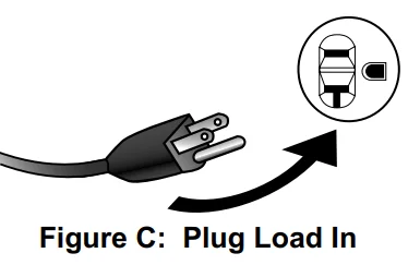
Overload Indicator
Note: The OVERLOAD light may turn on for a few seconds as a large device starts up. This is normal for loads approaching the capacity of this Generator.
- The total combined load through the outlet on the Generator must not exceed the running power of the unit.
- When approaching the maximum running watts of the Generator, the OVERLOAD indicator will blink. Adding more loads will overload the Generator.
- If the OVERLOAD light turns on and the Generator stops producing power, it has been overloaded.
- Turn off and disconnect all electrical devices and stop the Engine. Compare device requirements to the Generator rating and reduce the total wattage of connected devices if necessary. Move anything that may be limiting the generator’s ventilation away.
- Check if any circuit breakers have tripped and make sure that ALL circuit breakers are reset before starting the Generator again.
- Restart the Engine and reconnect devices while being careful not to overload the Generator.
Low Oil Indicator
- If the engine oil level is too low, the LOW OIL light turns on, and the engine will automatically shut off.
- The engine cannot be restarted until the proper amount of oil has been added. Add the appropriate type of oil until the oil level is at the proper level. SAE 10W-30 oil is recommended for general use.
Economy (ESC) Switch
- Turn the Economy (ESC) Switch ON to limit noise and fuel consumption for lighter generator loads.
- Turn the Economy (ESC) Switch OFF to operate the engine at full speed:
- When starting.
- When a heavy load is applied.
Stopping the Engine
To stop the engine in an emergency, turn the switch OFF. Under normal conditions, use the following procedure to shut off the generator:
- Turn all electrical load devices off and unplug them from the generator.
- If the Economy (ESC) Switch is ON, turn it to the OFF position.
- Close the Fuel Valve.
- Turn the switch OFF.
Maintenance
Many maintenance procedures, including any not detailed in this manual, will need to be performed by a qualified technician for safety. If you have any doubts about your ability to safely service the generator or engine, have a qualified technician service the generator instead.
Cleaning, Maintenance, and Lubrication Schedule
Note: This maintenance schedule is intended solely as a general guide. If performance decreases or if the generator operates unusually, check systems immediately. The maintenance needs of each generator will differ depending on factors such as duty cycle, temperature, air quality, fuel quality, and other factors. Note: The following procedures are in addition to the regular checks and maintenance explained as part of the regular operation of the engine and generator.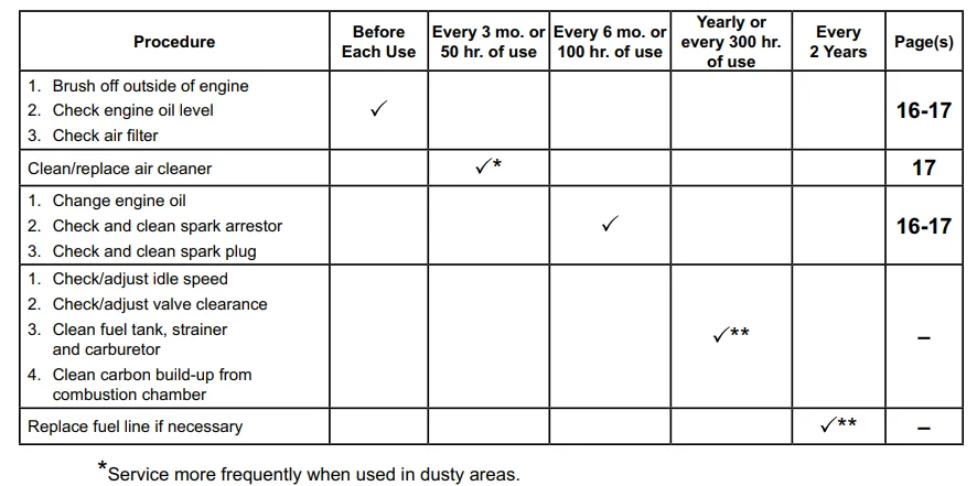
Checking and Filling Fuel
![]() WARNING! TO PREVENT SERIOUS INJURY FROM FIRE: Fill the fuel tank in a well-ventilated area away from ignition sources. If the engine is hot from use, shut the engine off and wait for it to cool before adding fuel. Do not smoke.
WARNING! TO PREVENT SERIOUS INJURY FROM FIRE: Fill the fuel tank in a well-ventilated area away from ignition sources. If the engine is hot from use, shut the engine off and wait for it to cool before adding fuel. Do not smoke.
- Clean the Fuel Cap and the area around it.
- Unscrew and remove the Fuel Cap.
- Remove the Strainer and remove any dirt and debris. Then replace the Strainer. Note: Do not use gasoline containing more than 10% ethanol (E10). Do not use E85 ethanol. Add fuel stabilizer to the gasoline, or the warranty is VOID. Note: Do not use gasoline that has been stored in a metal fuel container or a dirty fuel container. It can cause particles to enter the carburetor, affecting engine performance and/or causing damage.
- If needed, fill the Fuel Tank to about 1 inch under the fill neck of the Fuel Tank with 87 octane or higher unleaded gasoline that has been treated with a fuel stabilizer additive. Follow the fuel stabilizer manufacturer’s recommendations for use.
- Replace the Fuel Cap.
- Wipe up any spilled fuel and allow excess to evaporate before starting the engine. To prevent FIRE, do not start the engine while the smell of fuel hangs in the air.
Engine Oil Change
CAUTION! Oil is very hot during operation and can cause burns. Wait for the engine to cool before changing oil.
- Make sure the engine is stopped and is level.
- Lift and tilt the generator. Remove the Drain Plug from the bottom of the machine, then set the generator back down on a level surface.
- Clean the top of the Oil Fill Cap / Dipstick and the area around it. Remove the Cap / Dipstick, turning it counterclockwise.
- Place an oil drain pan under the generator and centered under the Drain Plug opening. Remove the Oil Drain Bolt, tilt the generator slightly to facilitate drainage, and wait for oil to drain completely. Recycle used oil.
- Tilt the generator and replace the Drain Plug, then set the generator back down on a level surface.
- Replace the Oil Drain Bolt and add the appropriate type of oil until the oil level is at the proper level. SAE 10W-30 oil is recommended for general use. Note: Make sure the generator is level when adding oil to prevent overfilling, which could cause engine damage.
- Check the oil level. The oil level should be up to the edge of the hole as shown.
- Thread the Oil Fill Cap / Dipstick back in clockwise.
NOTICE: Do not run the engine with too little oil. The engine will not start with low or no engine oil.
Air Filter Element Maintenance
- Remove the Air Filter Cover and the air filter elements and check for dirt. Clean as described below.
- Cleaning: For “paper” filter elements: To prevent injury from dust and debris, wear ANSI-approved safety goggles, NIOSH-approved dust mask/respirator, and heavy-duty work gloves. In a well-ventilated area away from bystanders, use pressurized air to blow dust out of the air filter. For foam filter elements: Wash the element in warm water and mild detergent several times. Rinse. Squeeze out excess water and allow it to dry completely. Soak the filter in lightweight oil briefly, then squeeze out the excess oil.
- Install the cleaned filter.
- Secure the Air Filter Cover before use.
Spark Arrestor Maintenance
TO PREVENT SERIOUS INJURY AND FIRE: Operate only with the proper spark arrestor installed.
![]() The operation of this generator may create sparks that can start fires around dry vegetation. A spark arrestor may be required. The operator should contact local fire agencies for laws or regulations relating to fire prevention requirements.
The operation of this generator may create sparks that can start fires around dry vegetation. A spark arrestor may be required. The operator should contact local fire agencies for laws or regulations relating to fire prevention requirements.
- Allow the generator to cool completely.
- Remove the bolts that hold the Spark Arrestor Bracket in place.
- Clean the Spark Arrestor using a wire brush (sold separately). Replace the arrestor if damaged.
- WARNING! TO PREVENT SERIOUS INJURY FROM ACCIDENTAL BRUSH FIRE, secure the Spark Arrestor back in place immediately after cleaning and before further operation.
Spark Plug Maintenance
- Disconnect the spark plug cap from the end of the plug. Clean out debris from around the spark plug.
- Using a spark plug wrench, remove the spark plug.
- Inspect the spark plug: If the electrode is oily, clean it using a clean, dry rag. If the electrode has deposits on it, polish it using emery paper. If the white insulator is cracked or chipped, the spark plug needs to be replaced.
NOTICE: Use only F6RTC-type spark plug or equivalent. Using an incorrect spark plug may damage the engine. - When installing a new spark plug, adjust the plug’s gap to the specification on the Specifications chart. Do not pry against the electrode; the spark plug can be damaged.
- Apply anti-seize material to spark plug threads. Install the new spark plug or the cleaned spark plug into the engine.
- Gasket-style: Finger-tighten until the gasket contacts the cylinder head, then tighten about 1/2–2/3 turn more.
- Non-gasket-style: Finger-tighten until the plug contacts the cylinder head, then tighten about 1/16 turn more. NOTICE: Tighten the spark plug properly. If loose, the spark plug will cause the engine to overheat. If overtightened, the threads in the engine block will be damaged.
- Apply the dielectric spark plug boot protector (not included) to the end of the spark plug and reattach the cap securely.
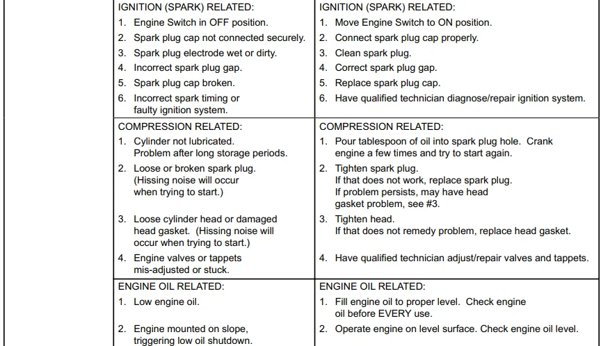
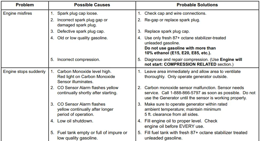
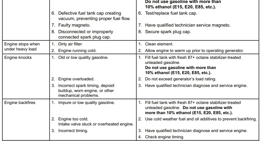
Troubleshooting
Visit our website at: http://www.harborfreight.com
Email our technical support at: [email protected]
Email our engine support at: [email protected]
For More Manuals By Predator, Visit ManualsLibraryy.
Predator 4550-Watts Portable Inverter Generator-FAQs
How long can the Predator 4550 run on a full tank?
The generator can run for over 16 hours on a full 3.72-gallon fuel tank, depending on load and usage.
What appliances can a 4550-watt generator power?
It can power large appliances, RV A/C units, power tools, lights, battery chargers, and small electronics safely.
How much fuel does the Predator 4550 hold?
The generator has a 3.72-gallon fuel tank with a built-in fuel gauge for easy monitoring.
Can a 4500-watt generator run a house?
A 4500-watt generator can power some household essentials like lights, fridge, and small appliances, but not the entire home with high-demand devices.
Can I run a refrigerator on this generator?
Yes, the Predator 4550 has enough power to run a refrigerator along with a few other small appliances at the same time.
Can it run an air conditioner?
It can run a small RV or window AC unit, but larger central AC units may require a higher wattage generator.
What is the difference between the Predator 4550 and 5000 models?
The 4550 model has more AC outlets (5) and GFCI protection, while both produce 120V and feature DC output. The 5000 model has fewer AC outlets but slightly higher wattage.
What type of oil should I use?
For most conditions, 10W-30 is recommended. In very cold weather, 5W-30 can also be used. Full synthetic oil is compatible.
Can I run this generator continuously 24 hours?
It is not recommended to run continuously without breaks. Use in intervals of 8–12 hours to allow cooling, refueling, and oil checks.
How much does the Predator 4550 cost?
The generator is priced around $649.99 (subject to promotions), offering great value compared to higher-priced competitors.


