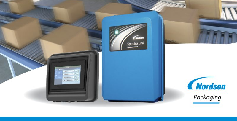
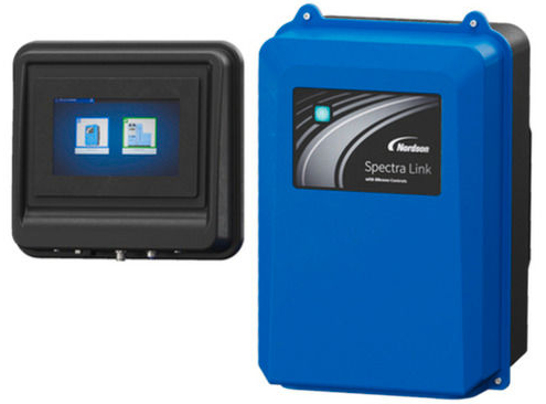
Nordson Spectra Link Pattern Controller
Installation Practices
- Install the equipment in accordance with the instructions provided in this document and in the documentation provided with auxiliary devices.
- Ensure that the equipment is rated for the environment in which it will be used. This equipment has not been certified for compliance with the ATEX directive nor as nonincendive and should not be installed in potentially explosive environments.
- Ensure that the processing characteristics of the material will not create a hazardous environment. Refer to the Safety Data Sheet (SDS) for the material.
- If the required installation configuration does not match the installation instructions, contact your Nordson representative for assistance.
- Position the equipment for safe operation. Observe the requirements for clearance between the equipment and other objects.
- Install lockable power disconnects to isolate the equipment and all independently powered auxiliary devices from their power sources. Refer to Equipment Shutdown for more information.
- Properly ground all equipment. Contact your local building code enforcement agency for specific requirements.
- Ensure that fuses of the correct type and rating are installed in the fused equipment.
- Contact the authority having jurisdiction to determine the requirement for installation permits or inspections.
Operating Practices
- Familiarize yourself with the location and operation of all safety devices and indicators.
- Confirm that the equipment, including all safety devices (guards, interlocks, etc.), is in good working order and that the required environmental conditions exist.
- Use the personal protective equipment (PPE) specified for each task. Refer to “Equipment Safety Information” or the material manufacturer’s instructions and SDS for PPE requirements.
- Use properly rated hearing protection when operating applicators. Noise emission levels can reach a maximum of 99 dB(A).
- Do not use equipment that is malfunctioning or shows signs of a potential malfunction.
- Do not use equipment with an open or missing enclosure. All openings require a fitting or plug.
Maintenance and Repair Practices
- Allow only personnel with appropriate training and experience to operate or service the equipment.
- Perform scheduled maintenance activities at the intervals described in this document.
- Relieve system hydraulic and pneumatic pressure before servicing the equipment.
- De-energize the equipment and all auxiliary devices before servicing the equipment.
- Use only new Nordson-authorized refurbished or replacement parts.
- Read and comply with the manufacturer’s instructions and the SDS supplied with equipment cleaning compounds. NOTE: SDSs for cleaning compounds that are sold by Nordson are available at www.nordson.com or by calling your Nordson representative.
- Confirm the correct operation of all safety devices before placing the equipment back into operation.
- Dispose of waste the cleaning compounds, and residual process materials according to governing regulations. Refer to the applicable SDS or contact the authority having jurisdiction for information.
- Keep equipment safety warning labels clean. Replace worn or damaged labels.
- Nordson supplied power cords (US and EU) have a locking feature at the plug to meet the IP rating of the unit. Refer to the Parts section for replacements.
Equipment Installation
Getting Started
Unpack the pattern controller. The box contains the following:
- Safety information document
- A template for the Vesa mount
- One small screwdriver
- One 3mm hex driver
- Four ports
- Two Ethernet connectors
- Two 8-pin position connectors
- One 12-pin position connector (triggers)
- One 7-pin position connector (encoder)
- One 4-pin position connector (standard Input/output)
Order of installation
- Unpack and mount the pattern controller
- Wire and install the position connectors
- Connect the power and start the pattern controller
- Commission the pattern controller
The following sections detail each installation step in greater detail.
NOTE:
- Do not use equipment with an open or missing enclosure. All openings require a fitting or plug.
Mounting the Equipment
Using the Vesa mount template document included with the ship-with kit, mark the location of the screw holes on the mounting surface and secure the pattern controller with customer-supplied thread lockers. Optionally, you can mount the pattern controller on a DIN rail using the Nordson DIN rail service kit, part number 1132438.
NOTES:
- Refer to Appendix B for equipment and installation specifications.
- The clips should support 12.72 kg (28 lbs), which is 4 times the weight of the equipment, which is 3.18 kg (7 lbs).
- The supplied VESA mount adapter utilizes a thread locker with mounting fasteners.
- The Customer is responsible for the strain relief of cables entering the unit.
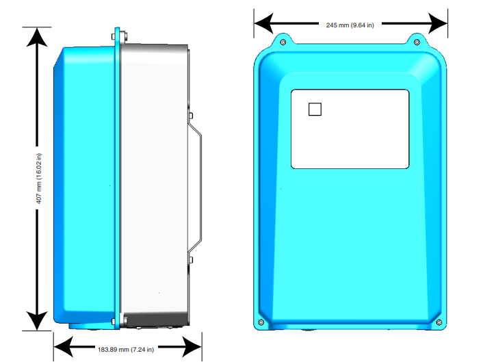
Equipment Dimensions
Connecting the Equipment
WARNING! Allow only qualified personnel to perform the following tasks. Follow the safety instructions in this document and all other related documentation.
General Wire Gage and Wiring Instructions
- Wire gage: Between 0.25 mm² (24 AWG) and 0.82 mm² (18 AWG)
- Wire preparation: Strip off 10 mm (0.40 in) from the ends to expose the wire.
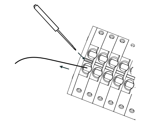
- Inserting Wires: Although you can insert the wire into either the top or bottom row, it is recommended that you use the bottom row. Push the wire in the appropriate slot. Check by lightly tugging on the wire to make sure it does not come out.
- Removing Wires: Using the provided small screwdriver, press down on the middle slot and pull the wire out as shown.

NOTE:
- For small gauge stranded wire 0.50 mm² (20 AWG or smaller), press the release button to open the clamp before inserting the wire.
Routing Wires through the Strain Relief
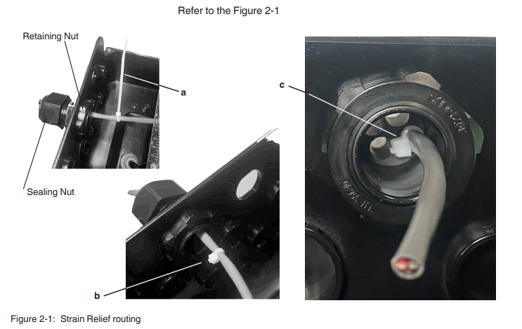
- Select a port where you want the wires to exit the enclosure.
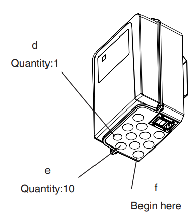
- (d) is reserved for the USB expansion kit p/n 1132549. Start with the back strain relief (f). Remove the back retaining nut, then screw the strain relief into the portal you selected. Secure the strain relief in place by installing the back retaining nut.
- Retaining nut torque: 8.5-9.0 Nm (75-80 in-lbs)

- Route the wires through the strain relief. Do the following to continue:
- Securely install the supplied zip tie around the wire (a).
- Using a cutter, remove the zip tie strap so that it is flush with the zip tie head (b).
- From outside the enclosure, pull the wire so that it is flush with the inside of the strain relief. The zip tie head should prevent the wire from being pulled out of the enclosure.
- Tighten the sealing nut of the strain relief down to fully compress the insert.
- Sealing nut torque: 9.0-9.6 Nm (80-85 in-lbs)
- For (d), reserved for USB.
- For (e) single orifice, cable diameter range: 0.21” (5.3 mm) – 0.334” (8.5 mm)
- For (e), four orifice, cable diameter range per orifice: 0.065” (1.65 mm) – 0.230” (5.84 mm)
Wiring the Terminal Blocks
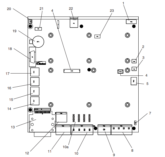
NOTES:
- For item 2 (TB10) & item 3 (TB8):
- Use wire gauge 0.25 mm² (24 AWG) – 1.50 mm² (16 AWG)
- Minimum temperature rating of wire: 75 °C
- Wire conductor: Copper
- Minimum voltage rating: 300V
- Torque: 0.23-0.45 Nm (2-4 in-lbs)


Connecting Main Power
The pattern controller is shipped with the main power connector pre-installed, making use of a V-Lock interlocking system that is IP54 rated.
- The external power connector from the factory is the US power cord (NEMA 5-15), part number 1132376.
- The optional EU power cord (CEE 7/VII) can be ordered from Nordson, part number 1132377.
NOTES:
- Refer to Appendix B for the Spectra Link Pattern Controller System Specifications.
- IP54 rating only with V-Lock power corset.
Connecting Standard Applicators 1-4
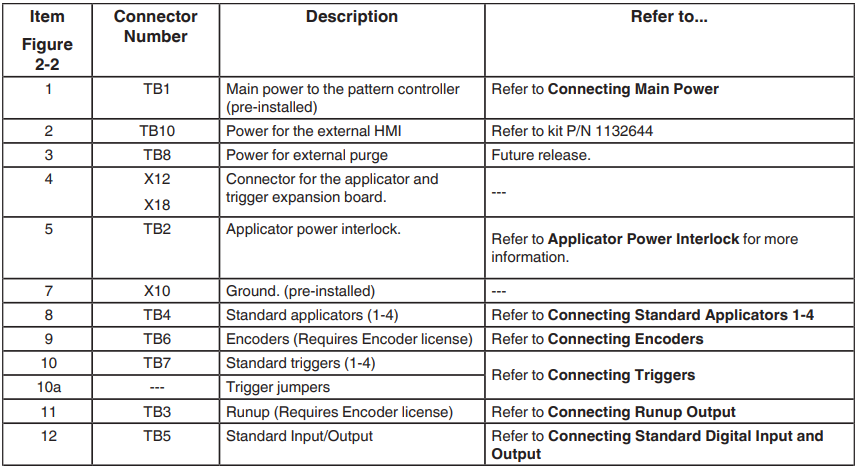
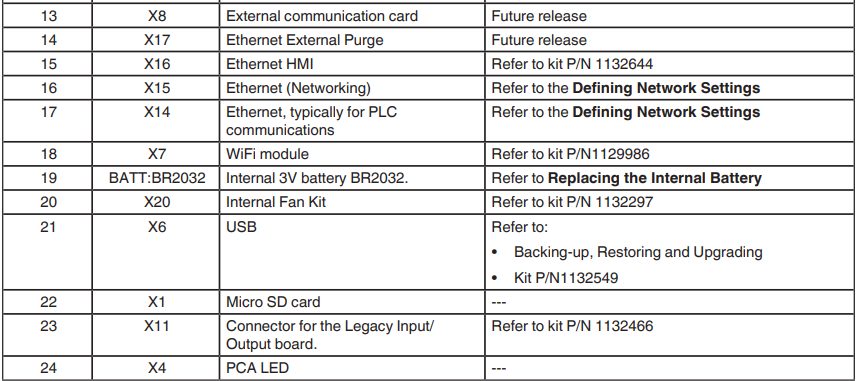
Refer to Figure 2.2, call out 8 (TB4). Wire the 8-pin connector as follows: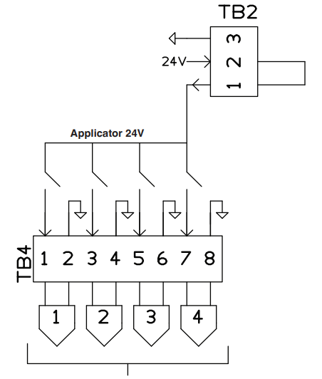
NOTES:
- Use wire gauge 0.25 mm² (24 AWG) – 2.5 mm² (14 AWG).
- Minimum temperature rating of wire 75 °C.
- Wire conductor: Copper.
- Minimum voltage rating: 300V.
- Each applicator output is 24V 2A rated. There is a total of 4A available to be distributed among the standard applicators 1-4, as well as applicators 5-8 if you install the 4-channel expansion kit (P/N 1132445) using the internal power supply.
- An external power supply with a higher power limit can be installed to TB2 on the Main PCA, bypassing the internal power supply, but in doing so, the UL certification will be void. Contact Nordson for more information.
Connecting Encoders
Refer to Figure 2.2, call out 9 (TB6). Use of an encoder requires an Encoder License, part number 1132400. Wire the 7-pin connector as follows: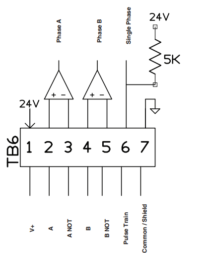
NOTES:
- Use wire gauge 0.25 mm² (24 AWG) – 1.5 mm² (16 AWG).
- Minimum temperature rating of wire 75 °C.
- Wire conductor: Copper.
- Minimum voltage rating: 300V.
Connecting Triggers
Refer to Figure 2.2, call out 10 (TB7). Wire the 12-pin connector as follows: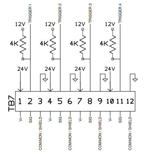
NOTES:
- Use wire gauge 0.25 mm² (24 AWG) – 1.5 mm² (16 AWG).
- Minimum temperature rating of wire 75 °C.
- Wire conductor: Copper.
- Minimum voltage rating: 300V.
Changing Trigger Jumpers
Refer to Figure 2.2, call out 10a. You can modify the trigger jumper for each installed trigger. Refer to the documentation that came with your trigger for more information. The default jumper setting is NPN/PNP (jumper on 2 and 3).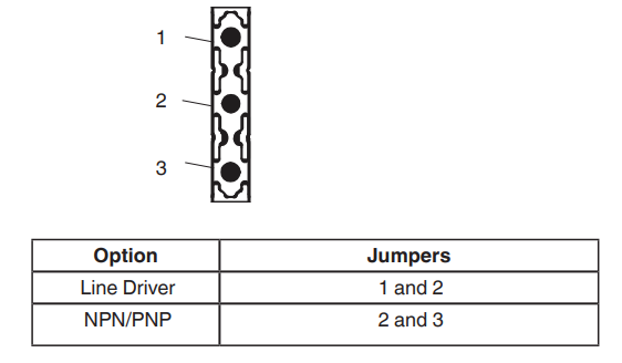
Connecting Runup Output
Refer to Figure 2.2, call out 11 (TB3). Wire the 8-pin connector as follows: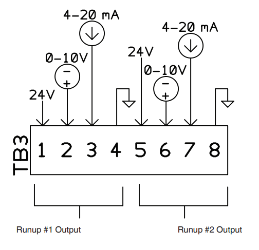
NOTES:
- Requires the Encoder License, part number 1132400.
- Use wire gauge 0.25 mm² (24 AWG) – 1.5 mm² (16 AWG).
- Minimum temperature rating of wire 75 °C.
- Wire conductor: Copper.
- Minimum voltage rating: 300V.
Connecting Standard Digital Input and Output
Refer to Figure 2.2, call out 12 (TB5). Wire the 4-pin connector as follows: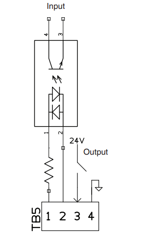
NOTES:
- By default, there is only one digital input, with a default assignment of Remote Enable, and one digital output, with a default assignment of Ready.
- Purchase the I/O Expansion kit, part number 1132446, to add an additional 8 inputs and outputs.
- Use wire gauge 0.25 mm² (24 AWG) – 2.5 mm² (14 AWG).
- Minimum temperature rating of wire 75 °C.
- Wire conductor: Copper.
- Minimum voltage rating: 300V.
Accessing the User Interface
The following details how you can access the Spectra Link pattern controller graphical user interface.
Connecting the External Display
Refer to Figure 2-2, call out 2 or 3.
- Connect power to TB10 (call out 2).
- Connect the Ethernet cable from the display to X16 (call out 15).
- Mount the display. You can purchase the DIN Rail kit, P/N 1132309, or mount it to a user-supplied stand.
Connecting from your PC
Refer to Figure 2-2. There are two options:
Option #1 – Purchasing (if permitted by your country) the WiFi kit, part number 1129986.
- Install the WiFi module to X7 (call out 18).
- Navigate to System Settings | Networking | WiFi and enable both the SSID broadcast On and WiFi On. The default broadcast name is myNordsonAP. The default password is Nordson321.
- From your computer, phone, or tablet, enter the following IP number: 192.168.243.1 from a browser (Chrome is recommended).
Option #2 – Direct Ethernet connection from Spectra Link to your PC.
- Connect an Ethernet cable from your PC to the Spectra Link main board X16 (call out 15).
- Enter the following IP number: 192.168.223.1 from a browser (Chrome is recommended).
Starting the Spectra Link Pattern Controller
Before Starting the Spectra Link
- All fasteners must be properly tightened and secured.
- Nordson provides the VESA mount adapter, which utilizes threadlocker with mounting fasteners.
- VESA mount and clips need to support a weight of at least 3.18 kg (28 lbs).
- You are responsible for the strain relief of cables entering our unit. Refer to Routing Wires through the Strain Relief for detailed instructions.
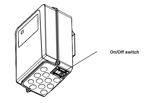
- Refer to the figure below for the location of the On/Off switch.

Commissioning
Commissioning Spectra Link
WARNING! Allow only personnel with appropriate training and experience to operate or service the equipment. The use of untrained or inexperienced personnel to operate or service the equipment can result in injury, including death, to themselves and others, and damage to the equipment.
WARNING! Allow only qualified personnel to perform the following tasks. Follow the safety instructions in this document and all other related documentation.
WARNING! Do not use equipment with an open or missing enclosure. All openings require a fitting or plug.
WARNING! For the installation of this equipment, the safety of any system incorporating the equipment is the responsibility of the assembler of the system. Customer is responsible for providing the main disconnect switch or circuit breaker per their local electric code. This unit needs to be located near the parent machine’s switch or circuit breaker, so it can be easily accessible.
Theory of Operation
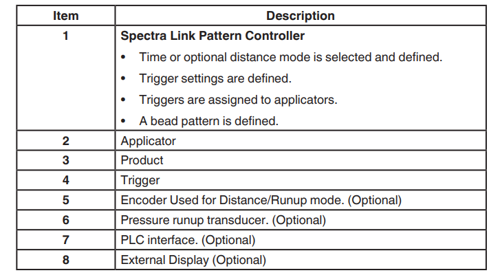
The following describes the general theory of the Spectra Link Pattern Controller.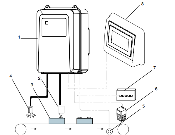
Figure 3-1: General Theory of Operation
About Centralized Monitor and Control of Multi-Functional Equipment
BBconn System Network Integration allows you to monitor and control any combination of up to four Spectra Link pattern controllers or ProBlue Flex melters from a single display. This integration allows the production line to operate as a more integrated and efficient system. Refer to https://nordson.info/Spectralink– section BBconn System Network Integration manual for setup and configuration information.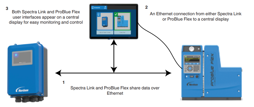
Figure 3-2: Theory of BBconn System Integration
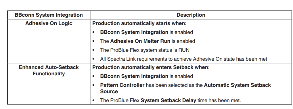
What you need to Know Before Starting the Commissioning Wizard
Although most Commissioning Wizard steps are straightforward, some components may require some additional information before starting the Commissioning Wizard. The following table details some important information you should know before starting the Commissioning Wizard.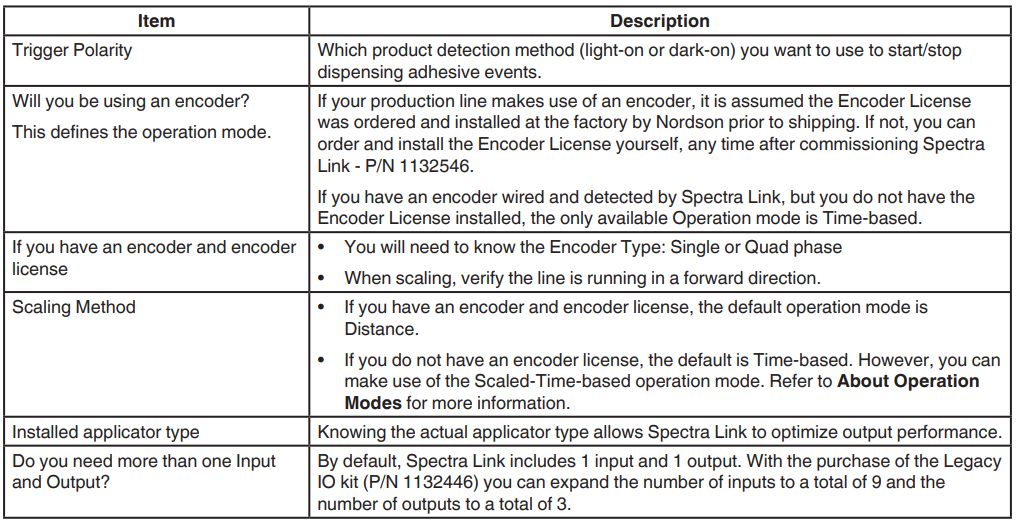
NOTES:
- After commissioning, you can make any changes by running the Commissioning Wizard again or navigating to the appropriate part of the user interface.
- Refer to Installing the Encoder License for more information.
About Operation Modes and Scaling
The following table details the operation mode and scaling options based on whether or not you have an encoder and an Encoder License installed.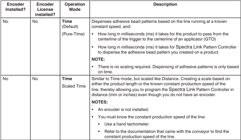
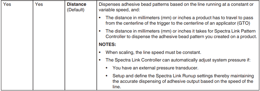
About Pressure Management and Runup
There are 2 options to convert an encoder signal to an analog (0-10V or 4-20mA) signal to make use of the runup option.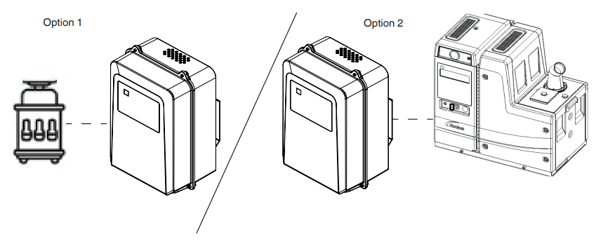
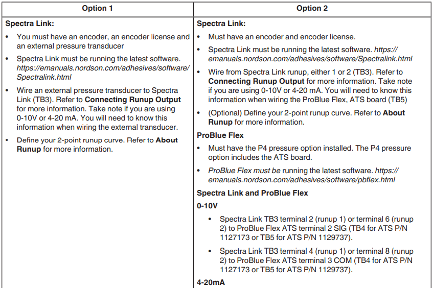

Getting Started – Commissioning
Commissioning is the process of defining basic operation, preferences, and machine settings.
NOTES:
- You must have already completed wiring the Spectra Link Pattern controller, including Input/Output and at least one applicator. Triggers and encoders are optional.
- The Setup and configuration of virtual triggers and encoders is done after completing the Commissioning Wizard. Refer to Virtual Triggers and Encoders – Theory of Operation for more information.
Commissioning the Spectra Link Pattern Controller
Upon first starting the Spectra Link Pattern Controller, the Commissioning Wizard automatically starts. If the Home screen appears instead of the Commissioning Wizard, you can restart the Commissioning Wizard by navigating from the Home | System Settings | Preferences and touching the Commissioning Wizard button.
- Language selection. Do the following to continue:

- Date and Time Settings.
- Select which Date and Time format you want to use.
- Enter the current date and time.
NOTE:
- You must manually change the system time to accommodate the time changes specific to your location.
Trigger Setting 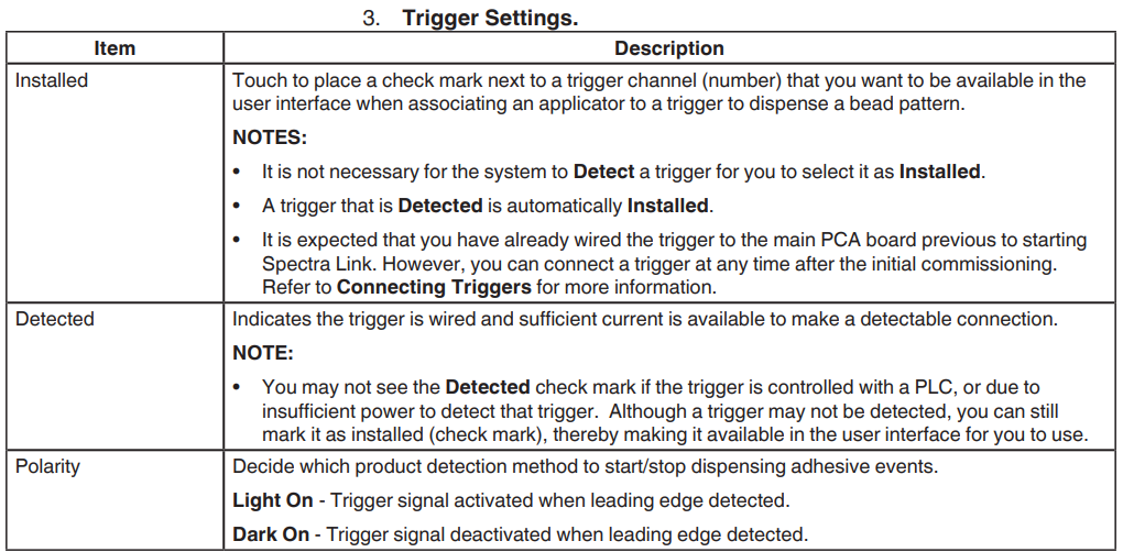
NOTES:
- If you did not wire/install any triggers, then Spectra Link assumes you want to make use of virtual triggers, which you must set up and define after completing the Commissioning Wizard. The only available bead type is Continuousness, without Knife Cut settings. However, you must purchase the Advanced Pattern License. Refer to Installing an Encoder or Pattern License for more information.
- At least one trigger must be installed when scaling the system. You can scale by speed or manually.
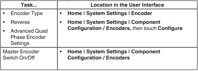
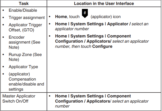
- You can update trigger settings at any time after commissioning. Refer to chapter Fine-Tuning the Operation Mode, Applicators, Triggers, and Runup for more information.

4. Encoder Settings. Refer to About Operation Modes and Scaling for more information. Do the following to continue.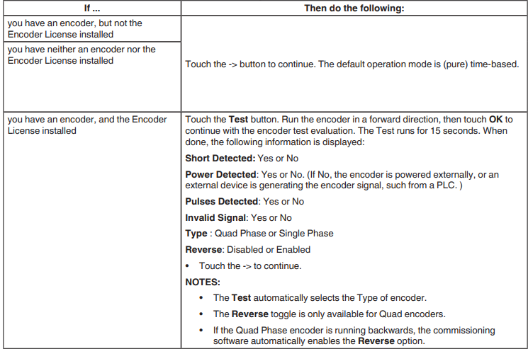
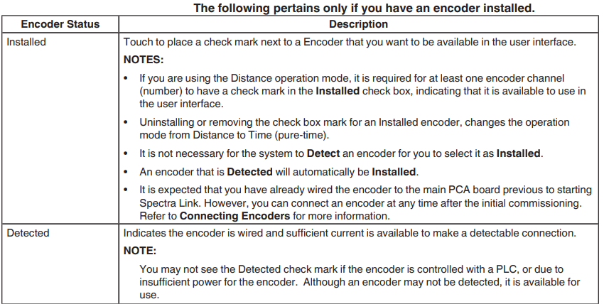
NOTES:
- You can set up and define a virtual encoder after completing the Commissioning Wizard. Refer to Virtual Triggers and Encoders – Theory of Operation for more information.
- You can update encoder settings at any time after commissioning. Refer to chapter Fine-Tuning the Operation Mode, Applicators, Triggers, and Runup for more information.

5. Applicator Settings. 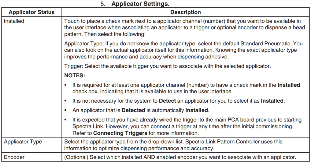
NOTES:
- You can update applicator settings at any time after commissioning. Refer to chapter Fine-Tuning the Operation Mode, Applicators, Triggers, and Runup for more information.

NOTE:
- The Encoder (assignment) and Runup Zone options are only available if you have an encoder and the Encoder License installed.
6. Scale and Units. Touch which system units you want to use for scaling and bead pattern creation.
- If your Operation mode is Time (pure time), then touch → to continue.
- If your Operation mode is Distance or Time (Scaled Time), then touch either mm or inch.
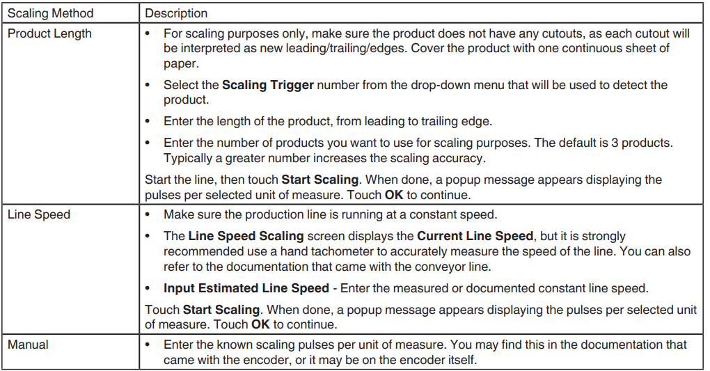
The following table items are available if you selected mm or inch as your System Units. Select your method for scaling you want to use, then touch Scale to continue and enter or select the requested information.
NOTE:
- If you have a Quad Phase encoder and if the Product Length or Line Speed scaling fails, touch the Commissioning Wizard back button and toggle the Reverse option.

7. Machine Settings.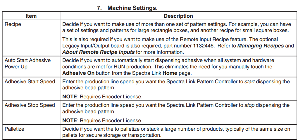
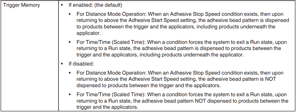
8. Input and Output Settings
By default, there is only one Input, with a default assignment of Remote Enable, and one Output, by default Ready.
NOTES:
- You can purchase the optional Legacy I/O board (kit P/N 1132446), which provides an additional eight inputs and an additional two outputs.
- The Legacy I/O board is required if you want to make use of the Remote Recipe feature.
9. Name this unit
Enter an easily identifiable name for this unit.
10. Review and Finish
Review the settings. You can touch ← the button to go back and make changes. If you are satisfied with the settings, touch FINISH.
NOTES:
- You can restart the Commissioning Wizard at any time by navigating from the Home screen | System Settings | Preferences and touching the Commissioning Wizard button.
- Refer to the chapter Fine-Tuning the Operation Mode, Applicators, Triggers, and Runup for more information.
Migrating from Spectra 30
It is strongly recommended that you upgrade your Spectra 30 software to the latest version before creating a backup. You can download the latest version of Spectra 30 by logging into your BBconn account or from https://emanuals.nordson.com/adhesives/software/Spectralink.html.
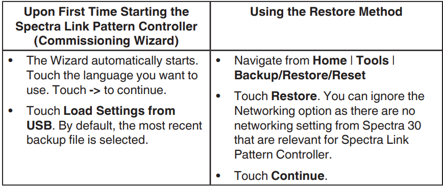
- From the Spectra 30 unit, create a backup file and save it to a FAT32-formatted USB drive. Refer to the Spectra 30 manual, P/N 1124631, for more information about upgrading software and creating a backup.
- Shut down the Spectra Link pattern controller, then tag and lockout the main power to the unit.
- Remove the cover using a 3 mm hex driver and insert a FAT32 formatted USB with the Spectra 30 backup (.NOR) file.
- Remove the tag and lockout, restore main power to the unit, and switch the Spectra Link Pattern Controller On and do the following:

- Touch OK. When done, the system automatically reboots itself.
For More Manuals By Nordson, Visit ManualsLibraryy.
Nordson Spectra Link Pattern Controller-FAQs
Q1. What is the Nordson Spectra Link Pattern Controller used for?
It controls adhesive application patterns in packaging, converting, and product assembly processes for accurate results.
Q2. How many patterns can the controller store?
The controller can store multiple patterns and jobs, allowing quick recall and consistent adhesive application.
Q3. How do I program a new adhesive pattern?
Use the keypad/display interface to enter pattern length, delay, and trigger settings, then save the program.
Q4. Can I run multiple guns with this controller?
Use the keypad/display interface to enter pattern length, delay, and trigger settings, then save the program.
Q4. Can I run multiple guns with this controller?
Yes, the Spectra Link can control several guns simultaneously, ensuring synchronized adhesive dispensing.
Q5. How do I adjust pattern timing?
Pattern timing is adjusted through the display menu by setting delay and duration values for each channel.
Q6. Does the controller support remote operation?
Yes, it can integrate with PLCs or production line systems for remote monitoring and control.
Q7. How can I troubleshoot errors or alarms?
The display shows error codes. Refer to the user manual’s troubleshooting section to identify and resolve issues.
Q8. How do I maintain the pattern controller for reliable performance?
Keep the unit clean, check connections regularly, and ensure software settings are updated as recommended.

