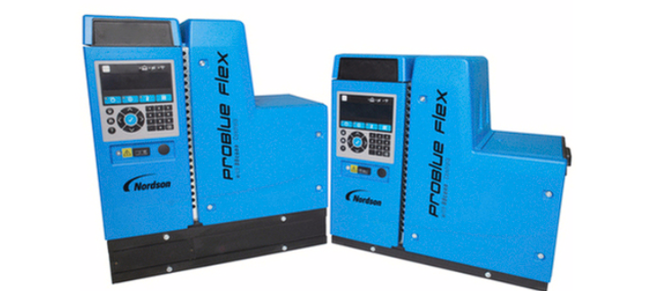
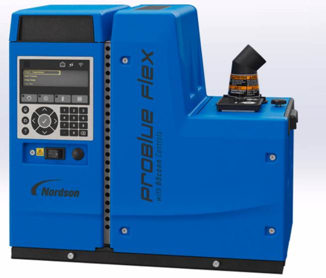
Nordson ProBlue Flex Melter with BBconn Controls
Description
This manual describes the installation and use of the Series 200/240V and 400/480V ProBlue Flex Adhesive Melter with BBconn Controls. These melters are designed to be configurable, meaning that each system is built according to the customer’s selection of options at the time of purchase. If optional hardware is not installed, then the unique functionality of the optional hardware is not available for use. However, an option can be purchased at any time based on the manufacturing needs.
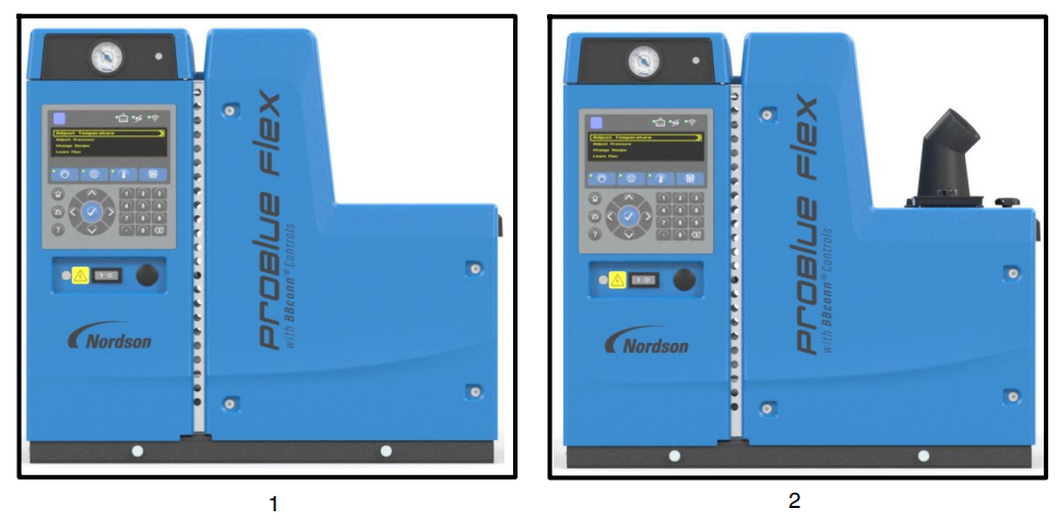
- ProBlue Flex adhesive melter
- ProBlue Flex adhesive melter with Fill System (Fill System is a customer option.)
Key Components
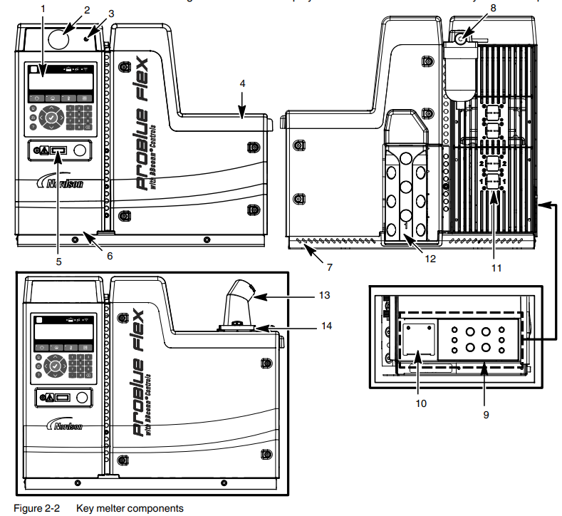
- OLED user interface
- Air pressure gauge (optional)
- Air pressure adjustment screw
- Lid assembly
- Melter On/Off switch
- Electrical enclosure door
- Chassis
- Incoming air filter
- Customer I/O knockout panel
- Incoming AC power plate
- Hose and applicator 12-pin connectors
- Hose manifold assembly
- Adhesive transfer hose connection (optional with Fill system)
- Fill system air filter (optional with Fill System)
Melter User Interface
The melter’s Organic Light Emitting Diode (OLED) user interface is used to navigate, configure, and fine-tune the system settings.
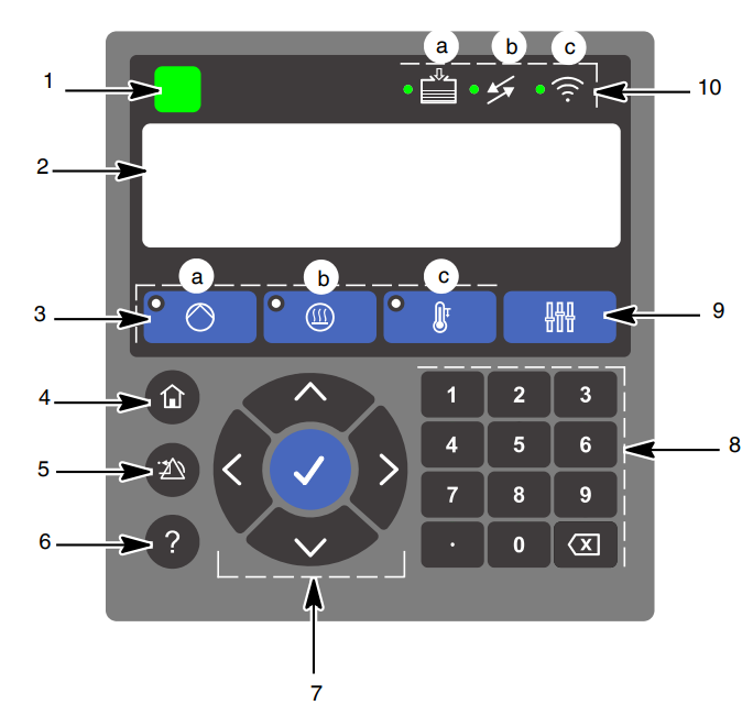
- System Status LED
- OLED Display
- Master Controls buttons
- a. Master Pump buttons with indicator
- b. Master Heater Control with indicator
- c. Master Temperature Setback with indicator
- Home button
- Clear Reset button
- Help button
- Navigation buttons
- Numeric keypad
- Additional Master Controls button
- Indicators:
- a. Fill (optional)
- b. System I/O or PLC Communication
- c. Wireless LED (optional)
Intended Use
Observe the safety instructions prior to using the ProBlue Flex adhesive melter. Nordson recommends obtaining detailed information on the materials to be used. Nordson will not be liable for personal injury or property damage resulting from unintended use. The ProBlue Flex adhesive melter is designed to be used:
- Only to melt and convey suitable materials, such as thermoplastic hot melt adhesives
- With compatible equipment manufactured by Nordson Corporation
- In non-explosive environments
Limitations of Use
Use the ProBlue Flex adhesive melter only for the purpose for which it is designed. The melter should not be used:
- In a defective condition
- With the electrical cabinet door open
- With the tank lid open
- In a potentially explosive atmosphere
- When the melter is not in compliance with the related specifications
The melter may not be used to process the following:
- Polyurethane hot melt adhesive (PUR) or thermoplastic with melt index (extruder-based materials)
- Explosive and flammable materials
- Erosive and corrosive materials
- Food products
Electromagnetic Compatibility (EMC)
The ProBlue Flex adhesive melter is intended for use in industrial applications. When operated in residential or commercial areas, the melter may cause interference in other electrical devices.
Theory Of Operation
The following diagram gives an overview of the system and its architecture. Understanding the functional blocks within the system and how they relate to each other can help with understanding the entire system and how it operates.
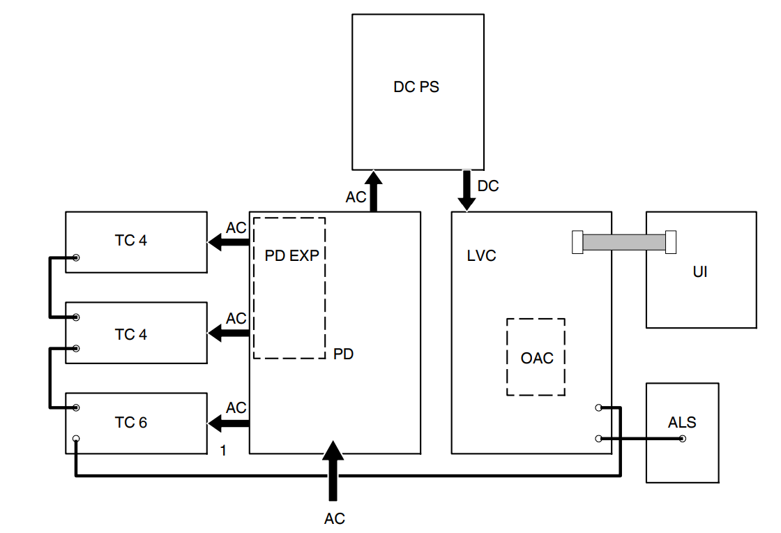

How the Blocks Operate as a System
The AC power line voltage enters the unit and energizes the DC power supply. The DC power supply powers the LVC and all other DC circuits. The LVC controls power to the AC power relays on the power distribution board. The LVC is the main control (CPU) and communications controller for the entire system. Communications is both within the system and outside the system. The primary function of the LVC is to interface with the user, communicate with the outside world, and direct the temperature controls. It also handles some I/O directly.
Melter Configuration Codes
The configuration code indicates the features that are included in your system, which was purchased. The system configuration code appears on the ID plate on the unit. Refer to the Melter Identification given on the following page.
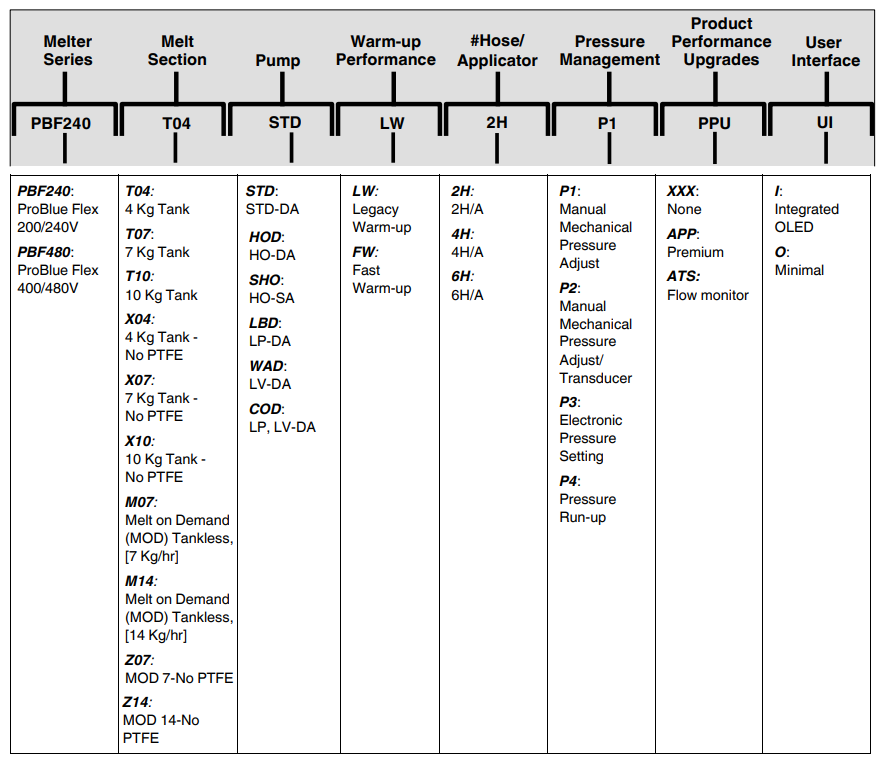
Melter Identification
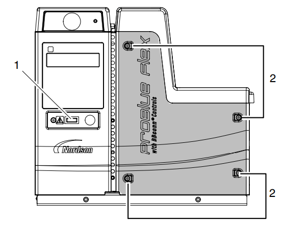
You will need the configuration code and part number of your melter when requesting service or ordering spare parts and optional equipment. The model and part number are indicated on the equipment identification plate that is located under the customer I/O knockout panel (see Figure 2-6).
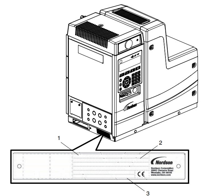
- . Unique number/Part number
- Configuration number
- Serial number
Installation
Quick-Start
If you have already installed the melter using the Installation Guide (P/N 1128353) that is provided inside the shipping container, and you have no questions concerning the installation, refer to the accompanying Quick Reference Guide (P/N 1128354) for setting up the melter using the OLED user interface. For detailed user interface setup instructions, refer to one of the following manuals:
- ProBlue Flex Adhesive Melter Using the OLED User Interface Manual (P/N 1128351).
- ProBlue Flex Adhesive Melter OEM User Interface Users’ Guide (P/N 1129255).
Installation Tasks
The installation sequence is as follows:
- Verify that the required environmental conditions and utilities exist.
- Unpack and inspect the melter.
- Mount the melter onto the parent machine or support structure.
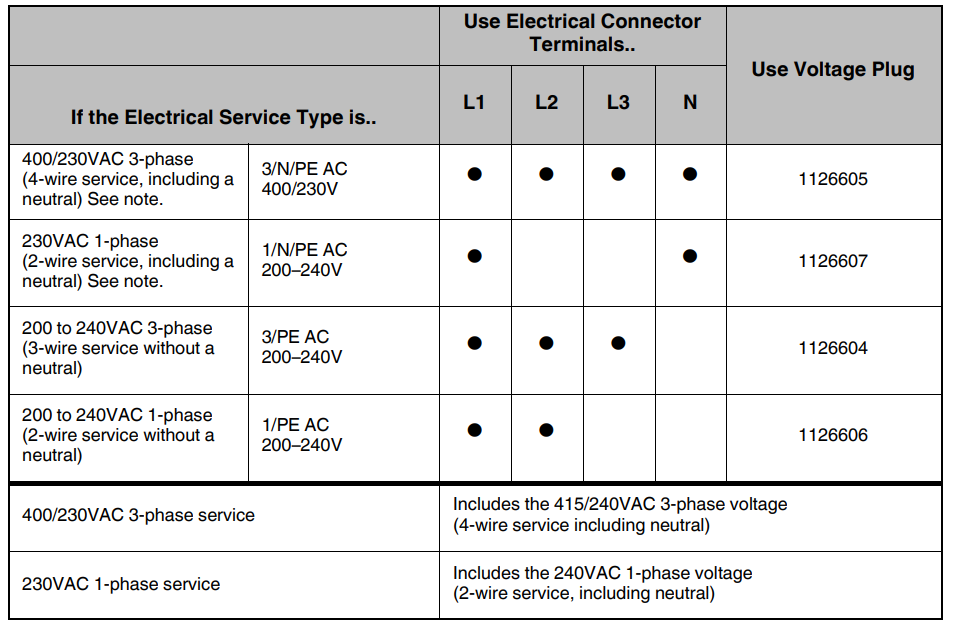
- Configure the electrical service.
- Connect a compressed air supply.
- Connect hot melt hoses and applicators.
- Set up the melter to work with the manufacturing process.
- Set up the melter’s inputs and outputs.
- Install optional equipment.
Melter Clearances
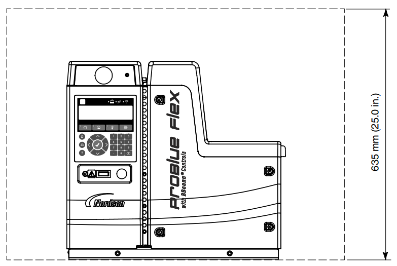
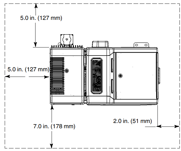
Figures 3-1 and 3-2 show the recommended clearances around the melter. Using the figures will ensure the setting of the minimum clearances that are required between the melter and:
- Hoses
- Cordsets
- Power cabling
- Tank lid
- E-Box door
- Air supply
- Pump
Ventilation
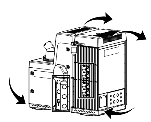
See Figure 3-3. Melters are cooled by convection. Air is drawn in through openings in the chassis of the melter, and is exhausted out of the ventilation slots at the top of the melter.
Electrical Power
Before installing the melter, ensure that the melter will not be overloaded and that the plant’s electrical service is rated to handle the power required by the melter and the hoses and applicators that you plan to use. Refer to Calculating Melter Power Requirements (Appendix A) for information about how to calculate the maximum allowable hose lengths and applicator wattage that can be used in your manufacturing application.
Compressed Air
To achieve maximum hot melt output, the melter must be connected to an air supply that is capable of providing 6.2 bar (90 psi) of dry, non-lubricated air. The actual pressure required for the melter to support your manufacturing process will depend on such factors as the type of hot melt and applicator you are using and the required dimensions of the hot melt bead.
Air consumption with the fill system by transfer rate:
- 17 SCFM at 3.4 bar (50 psi) to transfer 105 kg/hr (232 lb/hr) with a 4 m hose at a 4 m rise
- 22 SCFM at 4.1 bar (60 psi) to transfer 113 kg/hr (248 lb/hr) with a 9 m hose at a 4 m rise
- 30 SCFM at 6.2 bar (90 psi) to transfer 91 kg/hr (200 lb/hr) with an 18 m hose at a 4 m rise
- Average: 1.3 SCFM for a complete system [melter, 4 m transfer hose, 4.1 bar (60 psi)] operating at 11 kg/hr (25 lbs/hr) adhesive output.
Mounting the Melter
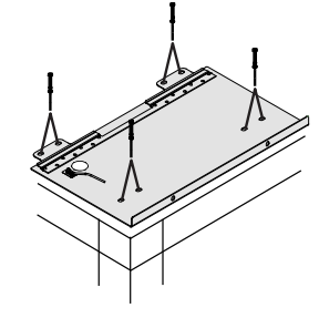
- Mark the sub-base bolt pattern on the parent machine or support structure and then drill holes for four 8 mm (5/16 in.) mounting bolts (customer-supplied). NOTE: The mounting sub-base has the same bolt-mounting pattern as
Nordson’s ProBlue® melters. - Bolt the sub-base to the parent machine using four 8-mm (5/16 in.) machine bolts with locking hardware. See the figure on the left. NOTE: If you want to route the incoming power line from underneath the melter and through the sub-base, refer to Connecting Incoming Power given on the following page.
- Carefully lower the melter onto the sub-base.
- Slide the melter forward so that the sub-base locking tabs securely connect with the melter.
- Lock the melter to the sub-base by reattaching the two M8 socket head cap screws located on the front of the chassis using an M6 hex wrench. NOTE: Torque the M8 socket head cap screws to 17 ft-lb (23 Nm).
- Connect the ground wire from the ground wire connection on the sub-base plate to the ground wire connection on the chassis. Reinstall the cover plate and fasten the screw.
Connecting Power Cables (contd)
Connect a Pump Control Signal
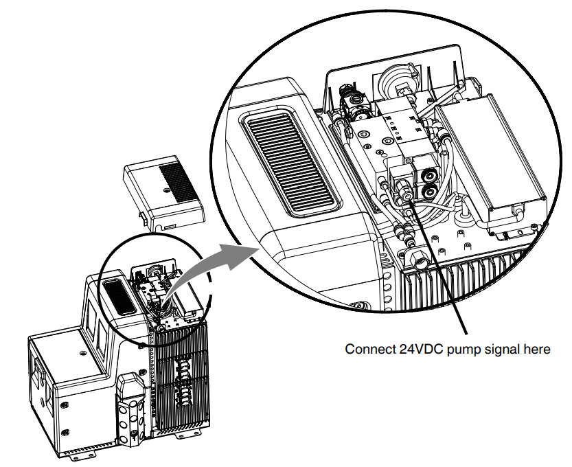
If your melter has a single-acting pump, you must provide 24VDC power to operate the pump. The single-acting pump is controlled by a 24VDC, 2.6 W solenoid valve. When power is applied to the solenoid valve, the pump piston moves downward, producing pressure and flow. Once the pump reaches the bottom of its stroke, it will remain there until power is removed. When power is removed from the solenoid valve, the pump piston moves upward, drawing adhesive from the tank and refilling the pump. When the pump reaches the top of its stroke, it will stop until power is again applied.
Connecting Power to the Solenoid Valve
- Make sure that the melter is turned off.
- Remove the regulator cover.
- Remove the entire connector and coil assembly from the upper solenoid valve.
- Connect the 24VDC control wiring to terminals 1 and 2 of the connector.
- Reinstall the connector and coil assembly to the upper solenoid valve.
- Route the 24VDC control wiring to the back corner of the electrical enclosure, farthest from the power supply. This will prevent the wiring from being pinched by the regulator cover.
- Reinstall the regulator cover.
Basic Melter Operation
Operator Level Tasks
The following is a list for accomplishing operator-level tasks:
- Filling the melter tank.
2. Starting the melter.
3. Operating the melter.
4. Shutting the melter down.
Before proceeding with the next set of tasks, make sure the melter is fully installed and connected as described in the accompanying Installation Guide (P/N 1128353).
Starting the Melter for the First Time
Before starting the melter for the first time, confirm that the melter is fully installed, including hoses and applicators, and any optional equipment.
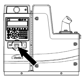
- Switch the melter on. See the figure on the left for the melter power switch location. NOTE: The melter goes through a self-check, and after all the LEDs and indicators briefly illuminate, the Commissioning Setup Wizard starts. Refer to the Commissioning Setup Wizard given on the following page.
- Fill the tank with adhesive and wait a few minutes until enough has melted to purge the air from the new pump.
- Remove the front panel of the melter by loosening the four latches.
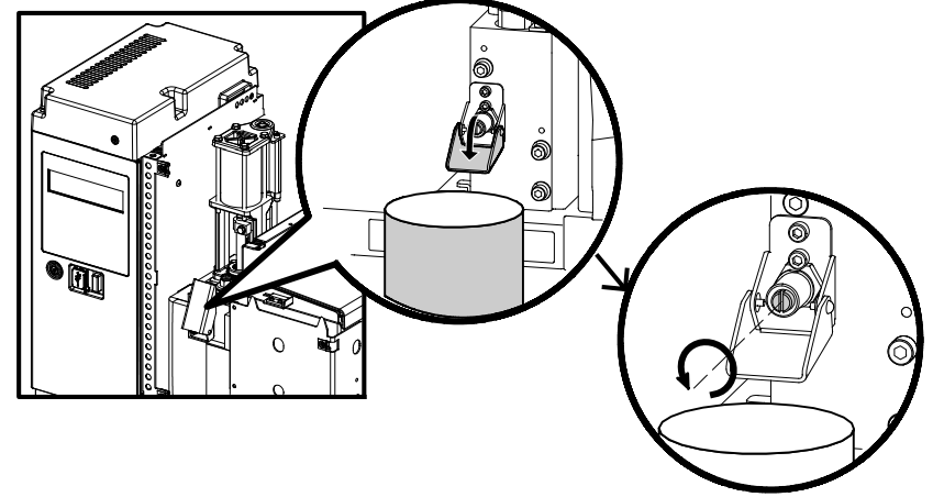
- See Figure 4-2. Lower the drain valve chute and open the drain valve.
- Set the pump air pressure to 1.03 bar (15 psi).
- Press on the OLED user interface to enable the pump.
- Allow adhesive to flow from the drain valve until there are no air bubbles present

- Close the drain valve.
Describing the Home Screen
After the Commissioning Setup Wizard process is complete, the Home screen appears.
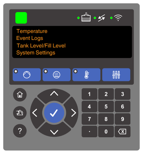
Refer to the accompanying User Interface Quick Reference Guide (P/N 1128354) for an overview of how to use the OLED user interface and the menu structure. The melter can be customized with several setup options. For detailed instructions on how to set up the menus for specific and advanced melter operating tasks, refer to one of the following manuals:
- ProBlue Flex Adhesive Melter Using the OLED User Interface Manual (P/N 1128351).
- ProBlue Flex Adhesive Melter OEM User Interface Manual (P/N 1129255).
Navigation Controls
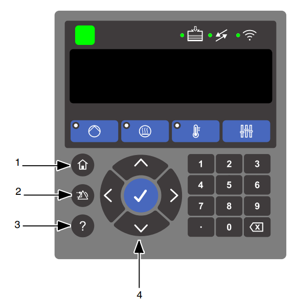
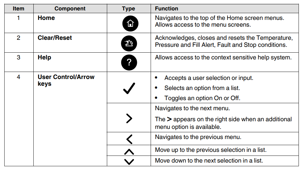
Use the Home screen components to monitor and change the melter settings. See Figure 4-4 for the location of the navigation controls. The descriptions of the functionalities are given on the following page.
Shutting Down the Melter
Shut down the melter when it will not be used for an extended period of time.
- Switch the melter off. The Automatic Pressure Discharge (APD) valve relieves the hydraulic pressure back to the tank.
- Disable the applicators as follows:
- Air-operated applicators: Turn off the air supply to the applicators.
- Electric applicators: Turn off the applicator driver, pattern controller, or timer.
Maintenance
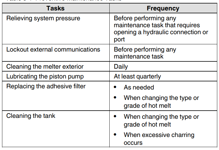
Table 5-1 describes the preventive maintenance tasks required to keep the melters operating within their specified limits and to prevent equipment malfunctions. For information about maintaining optional equipment, refer to the instructions provided with the equipment.
Relieving System Pressure
Before disconnecting any hydraulic fitting or opening any pressurized port, always complete the following procedure to safely relieve hydraulic pressure that may be trapped inside the melter, hoses, and applicators.
- Switch the melter off.

- Remove the front panel cover of the melter by loosening the four latches.
- Lower the drain chute and place a suitable waste container under the drain port. See Figure 5-2.
- Using a flat-tip screwdriver, slowly turn the drain valve counterclockwise three turns.
- Turn the drain valve clockwise until it stops (valve closed), and then wipe off and raise the drain chute.
- Reinstall the front panel cover of the melter by refastening the four latches
- Trigger the applicators until the hot melt no longer flows from the applicators
Cleaning the Melter
To prevent components from overheating due to heat build-up or loss of air circulation, regularly remove any hot melt that collects on the exterior of the melter, hoses, and applicators. If hot melt inadvertently spills inside the pump compartment or other interior spaces, the exterior panels can be removed to clean out the spilled hot melt.
Clean the Exterior of the Melter
- Use citrus-based cleaning compounds that are compatible with polyester, or use any of the following Nordson-recommended cleaning agents:

- Apply cleaning compounds using a soft cloth.
- Do not use pointed or sharp tools to clean the exterior surface.
Servicing the Pump
For comprehensive pump diagnostic and repair information, refer to SP Pump Diagnostics and Repair (Appendix B).
Supplies: The following table describes the lubricants and other compounds that are required during the re-assembly of the pump. Lubricants and other compounds are indicated in the illustrations by the symbols shown in Table 5-2.

Lubricating the Pump
- Switch the melter off.
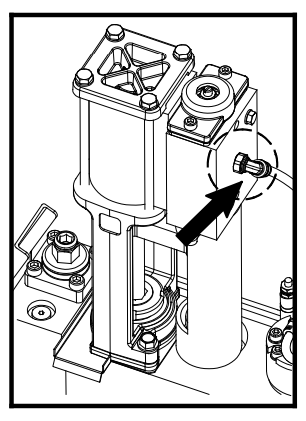
- Remove the pump covers, and then disconnect the air inlet line. See the figure on the left for the air inlet line location. NOTE: For instructions on how to remove the pump covers, refer to steps 1 – 3 in Remove the Pump from the Melter (All Pumps) in SP Pump Diagnostics and Repair (Appendix B).
- Place 3 – 4 drops of lubricant in the air inlet elbow. Use only SP Lubricating Oil, P/N 1120290.
- Reconnect the air line.
- Open the drain valve and operate the pump at high speed for 10 – 15 seconds.
- Close the drain valve and resume normal operation.
- Reinstall the pump covers.
Service Kit: For a complete listing of pump-related parts, refer to the SP Pump Diagnostics and Repair (Appendix B), and for service kits, see Service Kits under Parts (Section 8).
Replacing the Filter
Instructions for replacing the filter are also provided on the inside of the pump enclosure door.
- Relieve the system pressure. Refer to Relieving System Pressure at the beginning of this section.
- Use a 16 mm hex wrench or an adjustable wrench to loosen(counterclockwise) and then remove the filter.
- Properly dispose of the old filter.
- Confirm that the O-ring on the new filter is in good condition.
- Screw the filter into the pump body and then tighten the filter to 4.5 Nm (40 in.-lb).
- Reinstall the front panel cover of the melter by refastening the four latches.
- Resume normal operation.
Cleaning the Tank
To avoid problems that can occur when different hot melt materials are mixed or when hot melt char forms in the tank. Clean the tank when:
- Changing to a different type of hot melt
- Excessive char builds up inside the tank
- Empty the tank either by operating the system until the tank is empty or by pumping out the contents using the drain valve. Refer to Draining the Tank given earlier in this section.
- While the tank is at normal operating temperature, and while wearing appropriate protective equipment, wipe residual hot melt and loose char from the tank. Do not use sharp objects to scrape the tank, as damage to the release coating may result.
- Add hot melt system cleaner to the tank and clean the tank following the cleaner manufacturer’s instructions.
- Using the drain valve, pump the cleaner out of the tank. Refer to Draining the Tank given earlier in this section.
- If necessary, while wearing appropriate protective equipment, wipe the inside of the tank clean again.
- Replace the adhesive filter with a new one.
- If you are changing to a different type of hot melt adhesive, flush the system by pumping a minimum of one tank of the new adhesive through the system.
- Return the system to normal operation.
Troubleshooting
Overview
Problems with melter controls are often simple. Several things can be checked quickly and may resolve a problem with low effort. The following is a list of items that can be verified before extensive and more time-consuming troubleshooting is needed. It is organized by functional area. Just find the area and check the related items.
AC Power
- Incoming power LED ON (Power Distribution Board DS1)
- Check that the upstream AC disconnect is ON
- Check that TB1 is attached to the Power Distribution board
- Check that LED DS2 is ON
- Check voltage plugs or personality plugs (X9, X10, X11)
- Check the power switch on the door and the connection to the LVC
- Check contactors (DS1 on the Power Distribution Board and DS1 on LVC)
- Check cable between LVC X3 and the PDB (one of X4, X6, X7, X12)
- Check fuses on the power distribution board
- Check the harness between the PDB and the PDB Expansion Board (if present)
DC Power
- Check AC input connections at PDB X2
- Check the power supply LED on the power supply under the pneumatic cover
- Check DC output connections at LVC TB1
- Check the power switch on the E-Box door
Level
- Check cable connections to LVC X18 and X20
- Check cable connections to the level sensor
- Check sensor calibration
Troubleshooting Nordnet
- Check the Nordnet cables that are routed from board to board, starting at the LVC master.
- Observe the transmit/receive LEDs for the Nordnet master on the LVC board. Typically, both LEDs flash to indicate data transfer on the bus.
- Observe the LEDs on each board. In operation, all Nordnet nodes should have power. If you watch immediately after applying power, you should see each board power up in turn. Note that there is an order or sequence
to the bus. - One technique that should only be needed rarely is to add slaves to the bus one at a time. You must power the unit off when connecting or disconnecting slaves. Do not connect or disconnect Nordnet with DC power applied.
FOR MORE MANUALS BY NORDSON, VISIT MANUALSLIBRARYY
Nordson ProBlue Flex Melter with BBconn Controls-FAQs
Q1. What is the Nordson ProBlue Flex Melter used for?
The ProBlue Flex is designed for precise hot melt adhesive application, improving production efficiency with advanced BBconn controls.
Q2. How do I power on and set up the melter?
Switch on the main power, allow the melter to reach operating temperature, and use the BBconn touchscreen to configure temperature and pump settings.
Q3. What does the BBconn control system provide?
BBconn controls offer remote monitoring, digital temperature adjustment, data logging, and predictive maintenance alerts for improved operation.
Q4. How do I load adhesive into the melter tank?
Open the tank lid carefully, add clean adhesive pellets, and avoid overfilling beyond the recommended level in the user guide.
Q5. How can I monitor system performance?
Use the BBconn display or connected devices to track adhesive temperature, pump pressure, and system alerts in real time.
Q6. How do I perform daily maintenance?
Inspect hoses, nozzles, and filters for residue buildup, clean as recommended, and check for any visible leaks or blockages.
Q7. What safety features are included in the ProBlue Flex Melter?
It includes over-temperature protection, lockout features, and secure access controls to reduce operational risks.
Q8. How do I troubleshoot error messages on the BBconn display?
Refer to the error code section in the manual, reset the system if prompted, and contact Nordson support if issues persist.

