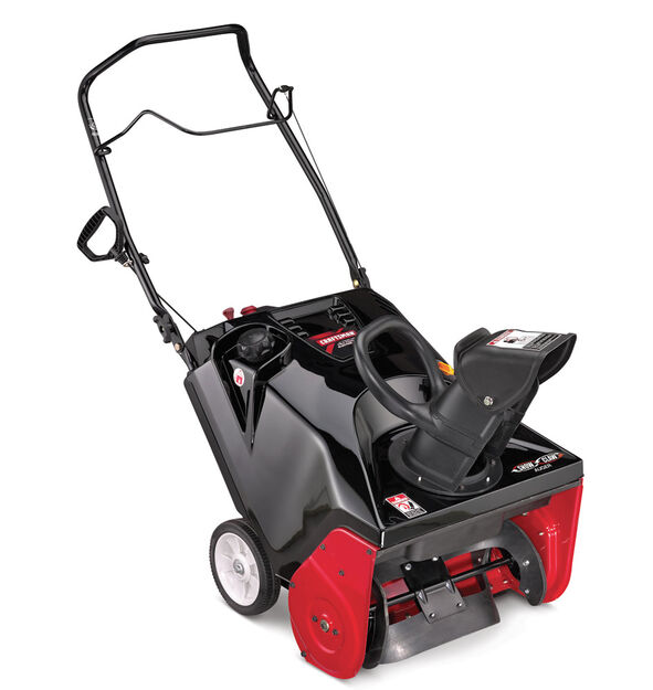
Craftsman 24788780 179cc Single-Stage Snow Blower
ASSEMBLY
Unpacking the Snow Thrower
- Open the top of the carton.
- Cut down the corners on the front of the carton and fold down the front side.
- Pull the snow thrower out of the carton. Be sure not to damage the chute or any cables attached to the chute, which is shipped under the shroud on the backside of the carton.
Assembly
Positioning the Upper Handle
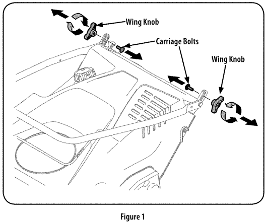
- Remove the wing knobs and carriage bolts from the top of the lower handle. See Figure 1. It is not necessary to remove the shoulder screw and flange lock nut below the wing knob and carriage bolt.

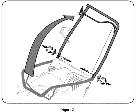
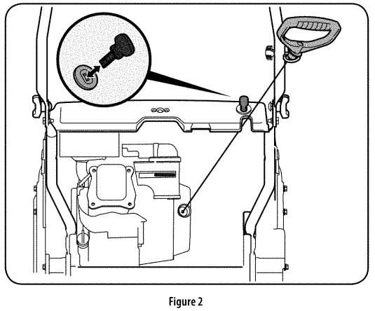
- Pivot the upper handle into the operating position. Be sure not to pinch any of the cables in the process. See Figure 2.

- Tighten the previously removed hardware to secure the handle in place. See Figure 2.
Installing the Chute
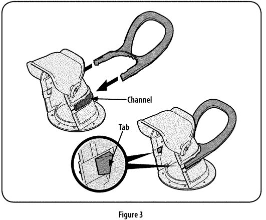
- Place the chute handle on the lower chute as shown in Figure 3. Be certain that the handle is aligned in the channel on the chute, and the tabs snap into place.

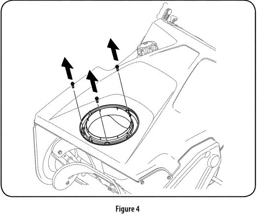
- Remove the screws in the chute base. See Figure 4.

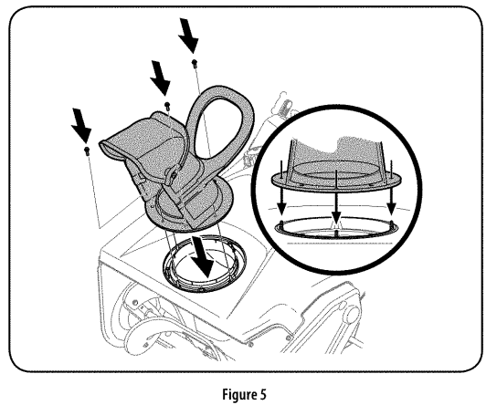
- Align the holes in the chute base with the holes in the lower chute and secure with the previously removed screws. See Figure 5.

Installing the Recoil Starter Handle
- Remove the eye bolt and handle knob from the manual bag.
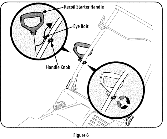
- Place the eye bolt and handle knob on the upper handle as shown in Figure 6. Do not fully tighten the hardware until instructed to do so. NOTE: The opening of the eye bolt should face toward the back of the snow thrower.

- Slowly pull the recoil starter handle up towards the eye bolt.
- Slip the recoil starter rope into the eye bolt from the back side of the snow thrower. See Figure 6.
- Securely tighten the eye bolt and handle knob.
Set-Up
Fuel Recommendations
Use automotive gasoline (unleaded or low-leaded to minimize combustion chamber deposits) with a minimum of 87 octane. Gasoline with up to 10% ethanol (E10) or 15% MTBE (Methyl Tertiary Butyl Ether) can be used. Never use an oil/gasoline mixture or dirty gasoline. Avoid getting dirt, dust, or water in the fuel tank. Do NOT use E15 or E85 gasoline.
- Refuel in a well-ventilated area with the engine stopped.
- Do not smoke or allow flames or sparks in the area where the engine is refueled or where gasoline is stored. Do not overfill the fuel tank. After refueling, make sure the tank cap is closed properly and securely.
- Be careful not to spill fuel when refueling. Spilled fuel or fuel vapor may ignite. If any fuel is spilled, make sure the area is dry before starting the engine.
- Avoid repeated or prolonged contact with skin or breathing of vapor.
Adding Fuel
- Remove the gas cap, check the fuel level, and add fuel if necessary. Fill the tank until the fuel reaches 1/2″ below the bottom of the filler neck to allow for fuel expansion. Be careful not to overfill.
Checking & Adding Oil
- Place the snow thrower on a flat, level surface.
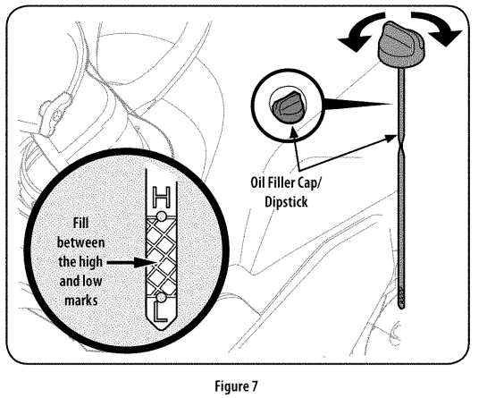
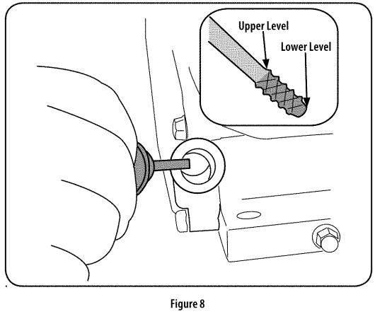
- On some models, the oil filler cap/dipstick can be accessed on the left side of the shroud. See Figure 7. On other models, the oil filler cap/dipstick can be accessed at the rear of the snow thrower. See Figure 8.


- Remove the oil filler cap/dipstick and wipe the dipstick clean.
- Insert the oil filler cap/dipstick into the oil filler neck, but do not screw it in.
- Remove the oil filler cap/dipstick. If the level is low, slowly add oil until the oil level registers between the upper level and lower level.
- NOTE: Do not overfill. Overfilling with oil may cause smoking, hard starting, or spark plug fouling. Replace and tighten the oil filler cap/dipstick firmly before starting the engine. NOTE: DO NOT allow the oil level to fall below the lower level on the dipstick. Doing so may result in equipment malfunctions or damage. NOTE: To change the oil in your engine, see the Maintenance section of this manual.
OPERATION
Now that you have set up your snow thrower, it’s important to become acquainted with its controls and features. Refer to Figure 1.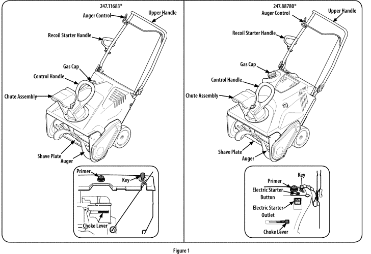
NOTE: This Operator’s Manual covers several models. Features may vary by model. Not all features in this manual are applicable to all models, and the unit depicted may differ from yours.
NOTE: References to LEFT, RIGHT, FRONT, and REAR indicate that position when facing forward in the operation position.
Choke Control
Activating the choke control closes the choke plate on the carburetor and aids in starting the engine. The choke lever slides between the RUN and CHOKE positions.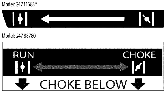
Primer
Pressing the primer, making sure to cover the vent hole when pushing, forces fuel directly into the engine’s carburetor to aid in cold-weather starting.
Recoil Starter Handle
The recoil starter handle is used to start the engine.
Gas Cap
Remove the gas cap to add fuel.
Key
The key is a safety device. It must be fully inserted in order for the engine to start. Remove the key when the snow thrower is not in use.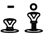
NOTE: Do not turn the key in an attempt to start the engine. Doing so may cause it to break.
Auger
When engaged, the auger rotation draws snow into the auger housing and throws it out the discharge chute. Rubber paddles on the auger also aid in propelling the snow thrower as they come in contact with the pavement.
Auger Control
Located on the upper handle, the auger control handle is used to engage and disengage the drive to the auger. Squeeze the control handle against the upper handle to engage the auger; release it to disengage.
Chute Assembly
Rotate the discharge chute to the left or right using the control handle. The pitch of the discharge chute controls the angle at which the snow is thrown. Loosen the wing knob on the side of the discharge chute before pivoting the discharge chute upward or downward. Retighten the knob once the desired position has been achieved.
Shave Plate
The shave plate maintains contact with the pavement as the snow thrower is propelled, allowing snow close to the pavement’s surface to be discharged.
Before Starting the Engine
WARNING: Read, understand, and follow all the instructions and warnings on the machine and in this manual before operating.
Starting the Engine
Recoil Starter
WARNING: Always keep hands and feet clear of moving parts. Do not use a pressurized starting fluid. Vapors are flammable.
WARNING: To avoid carbon monoxide poisoning, make sure the engine is outdoors in a well-ventilated area.
- Make certain the auger control is in the disengaged (released) position.
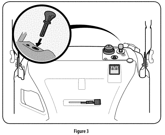
- Insert ignition key into slot. Make sure it snaps into place. Do not attempt to turn the key. See Figure 2 for model 247.11683 and see Figure 3 for model 247.88780. NOTE: The engine cannot start unless the key is fully inserted into the ignition switch.


- Push the choke lever to the CHOKE position.
- If the engine is warm, place the choke in the RUN position instead of CHOKE.
- Push the primer five to seven (5-7) times for model 247.11683 and three (3) times for model 247.88780, making sure to cover the vent hole when pushing.
- If the engine is warm, push the primer only once.
- Grasp the recoil starter handle and slowly pull the rope out. At the point where it becomes slightly harder to pull the rope, slowly allow the rope to recoil.
- Pull the starter handle with a firm, rapid stroke. Do not release the handle and allow it to snap back. Keep a firm hold on the starter handle and allow it to slowly recoil.
- Allow the engine to warm up for several minutes, adjusting the choke toward the RUN position. Wait until the engine runs smoothly before each choke adjustment.
Electric Starter (If equipped)
Determine that your home’s wiring is a three-wire grounded system. Ask a licensed electrician if you are not certain.
If you have a grounded three-prong receptacle, proceed as follows:
- Make certain the auger control is in the disengaged (released) position.
- Insert ignition key into slot. Make sure it snaps into place. Do not attempt to turn the key. See Figure 3 for model 247.88780. NOTE: The engine cannot start unless the key is fully inserted into the ignition switch.
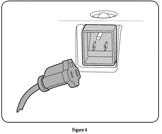
- Plug the extension cord into the outlet located on the engine’s surface. Plug the other end of the extension cord into a three-prong 120-volt, grounded, AC outlet in a well-ventilated area. See Figure 4.

- Push the choke lever to the CHOKE position.
- If the engine is warm, place the choke in the RUN position instead of CHOKE.
- Push the primer three (3) times for model 247.88780, making sure to cover the vent hole when pushing.
- If the engine is warm, push the primer button only once.
- Push the starter button to start the engine.
- Once the engine starts, release the starter button.
- Allow the engine to warm up for several minutes, adjusting the choke toward the RUN position. Wait until the engine runs smoothly before each choke adjustment.
- When disconnecting the extension cord, always unplug the end at the three-prong wall outlet before unplugging the opposite end from the snow thrower.
Stopping the Engine
- Run the engine for a few minutes without engaging the auger before stopping to help dry off any moisture on the engine.
- To stop the engine, remove the key and store it in a safe place. NOTE: Remove the key to quickly stop the engine in the event of an emergency.
- Wipe all the snow and moisture away from the engine control area.
Engaging the Auger
Engage the auger by squeezing the auger control against the upper handle. Release the control to stop the auger.
Engaging the Drive
Lift up slightly on the upper handle to allow the rubber paddles on the auger to contact the pavement and propel the snow thrower forward. Pushing downward on the handle will raise the auger off the ground and stop the forward motion.
NOTE: Excessive upward pressure on the handle will result in premature wear to the rubber auger paddles.
Clearing a Clogged Discharge Chute
Hand contact with the rotating impeller inside the discharge chute is the most common cause of injury associated with snow throwers. Never use your hand to clean out the discharge chute. To clear the chute:
- Stop the engine. See instructions above for how to stop the engine.
- Wait 10 seconds to be sure the impeller blades have stopped rotating.
- Always use a clean-out tool or stick, not your hands.
Operating the Snow Thrower
Once the auger drive is engaged, roll the snow thrower into the layer of snow to be removed. Adjust the chute so that the snow is not thrown over other snow that is to be removed. Prevent possible property damage or personal injury from object ricochet by planning your snow throwing pattern to avoid discharge towards windows, walls, cars, etc.
Do not overload machine capacity by attempting to clear snow at too fast a rate. Never operate this machine without good visibility or light. Always be sure of your footing and keep a firm hold on the handles. Walk, never run when operating a snow thrower. Look down and behind, and use care when backing up.
SERVICE AND MAINTENANCE
MAINTENANCE SCHEDULE
Follow the maintenance schedule given below. This chart describes service guidelines only. Use the Service Log column to keep track of completed maintenance tasks. To schedule service from Sears Parts & Repair, call 1-888-331-4569.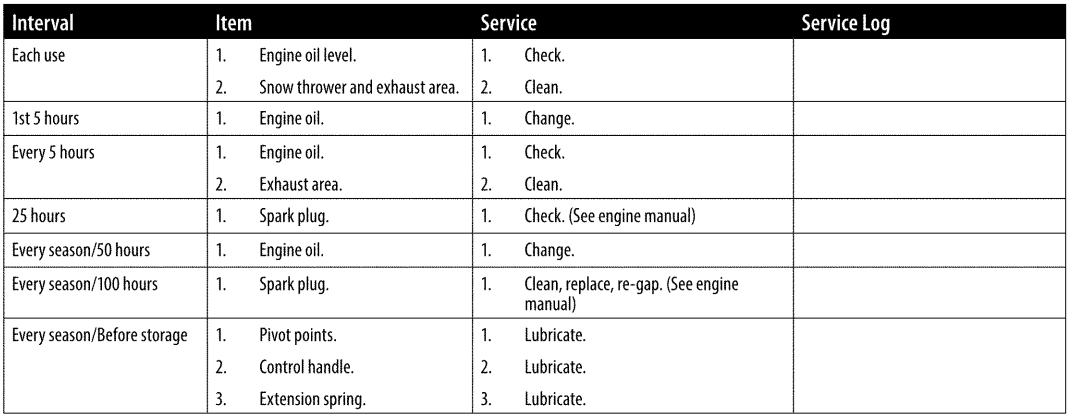
Maintenance
Engine
Refer to the Engine Operator’s Manual for all engine maintenance procedures. Checking, adding, and changing oil are also found in this manual.
Lubrication
Lubricate the pivot points on the control handle and the extension spring at the end of the control cable with a light oil once every season and before the snow thrower is put into storage at the end of the season.
Adjustments
Shave Plate
To check the adjustment of the shave plate, place the machine on a level surface. The wheels, the shave plate, and the auger paddles should all contact the level surface. Note that if the shave plate is adjusted too high, snow may blow under the auger housing. If the shave plate wears out excessively, or the snow thrower does not self-propel, the shave plate may be too low to the ground and needs to be adjusted.
NOTE: On new snow throwers or machines with a new shave plate installed, the auger paddles may be slightly off the ground.
To adjust the shave plate proceed as follows:
- Run the snow thrower until the fuel tank is empty.
- Pull the starter cord until resistance is felt. Then tip the snow thrower back until it rests on the handles. To ensure that the snow thrower does not tip forward, it may be necessary to secure the handle to the ground with a block or other object.
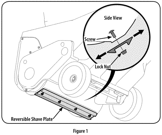
- Loosen the four flange lock nuts and carriage screws that secure the shave plate to the housing. See Figure 1. Move the shave plate to the appropriate position and retighten the nuts and screws securely.

- Tip the snow thrower back to the operating position and pull the recoil starter handle a few times to see if it is difficult to pull.
- If the starter is difficult to pull, remove the spark plug and pull the handle several times to ensure that any oil trapped in the engine head is removed. CAUTION: Oil may come out of the spark plug hole when it is removed and the starter handle is pulled.
- Inspect the spark plug. If it is wet, clean off any oil before re-installing.
Control Cable
As a result of both the control cable and the auger drive belt stretching due to wear, periodic adjustments may be necessary. If the auger seems to hesitate when rotating, proceed as follows:
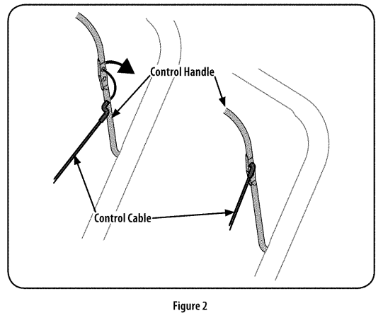
- The upper hole in the control handle provides for an adjustment in cable tension. To adjust, disconnect the end of the control cable from the bottom hole in the control handle and reinsert it in the upper hole. Insert the cable from the outside as shown in Figure 2.

- Test the snow thrower to see if there is a noticeable difference. If, after the adjustment to the control cable, the auger still hesitates when rotating, see Auger Drive Belt Replacement for instructions on replacing the belt.
Chute Assembly
Refer to the Assembly section for instructions on adjusting the chute assembly.
Service
Auger Drive Belt Replacement
- Run the snow thrower until the fuel tank is empty.
- Pull the recoil starter handle until resistance is felt. Then tip the snow thrower back until it rests on the handles.
- Slide a board up through the auger and through the chute to secure the auger in place.
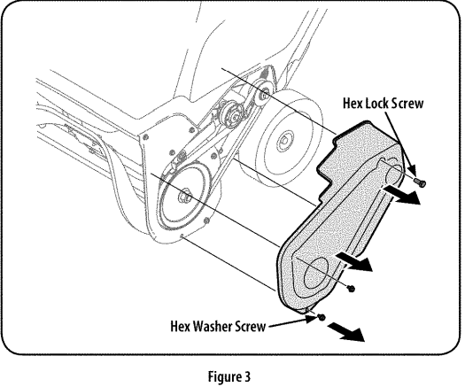
- Remove the belt cover by removing the two hex washer screws and one hex lock screw that secure it to the frame. See Figure 3.

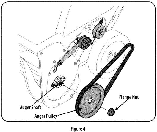
- Remove the flange nut that secures the auger pulley to the auger shaft. See Figure 4.

- Remove the auger pulley and the belt.
To replace the belt follow these instructions and refer to Figure 5: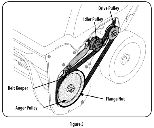
- Route the belt around the drive pulley and under the idler pulley.
- Route the end of the belt around the auger pulley and slide the pulley back onto the auger shaft. It may be necessary to push down on the idler pulley to get the auger pulley under the belt keeper.
- Replace the flange nut and tighten securely.
- Squeeze the auger control lever against the upper handle and reinstall the belt cover removed earlier.
- Remove the board from the auger and chute.
Replacing Auger Paddles
The snow thrower auger’s rubber paddles are subject to wear and should be replaced if any signs of excessive wear are present.
To change the rubber paddles, proceed as follows and refer to Figure 6: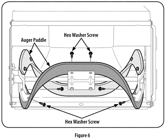
- Run the snow thrower until the fuel tank is empty.
- Pull the recoil starter handle until resistance is felt. Then tip the snow thrower back until it rests on the handles.
- Remove the existing rubber paddles by unthreading the hex washer screws that secure them to the auger. See Figure 6. NOTE: The auger paddles should be replaced one at a time so that the auger paddle still attached can be used as an example for positioning and re-installing the new auger.
- Secure the replacement rubber paddles to the auger using the hardware removed earlier.
A full auger replacement kit, including rubber paddles and hex washer screws, may be obtained through Sears Parts & Repair or by calling 1-888-331-4569. Ask for part 753-06469.
Reversing or Replacing Shave Plate
The shave plate is attached to the bottom of the auger housing and is subject to wear. It should be checked periodically. There are two wearing edges, and the shave plate can be reversed.
- Run the snow thrower until the fuel tank is empty.
- Pull the recoil starter handle until resistance is felt. Then tip the snow thrower back until it rests on the handles.
- Remove the four carriage bolts and flange lock nuts that attach it to the snow thrower housing. Refer to Figure 1 on page 12.
- Reverse the existing shave plate or install a new one, making sure the new shave plate and the heads of the carriage bolts are on the inside of the housing.
- Adjust the shave plate as instructed on page 12.
- Tighten securely once adjusted.
A new shave plate may be obtained through Sears Parts & Repair or by calling 1-888-331-4569. Ask for part #731-07667.
TROUBLESHOOTING
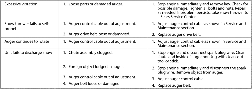
This section addresses minor service issues. To locate the nearest Sears Service Center or to schedule service, call 1-888-331-4569.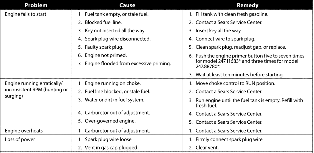
For More Details Visit our website: www.craftsman.com
For More Manuals By Craftsman, Visit ManualsLibraryy.
Craftsman 24788780 179cc Single-Stage Snow Blower-FAQs
How does a single-stage snow blower work?
A single-stage snow blower uses its auger to scoop up snow and throw it out through the chute in one motion, making it ideal for light to moderate snowfalls.
How do I start my Craftsman snow blower for the first time?
Set the choke to FULL, move the throttle to FAST, turn the fuel valve on, insert the safety key, and pull the starter cord or use the electric start if equipped.
How much oil does the Craftsman 24788780 snow blower need?
This model requires about 20 ounces of 4-cycle engine oil. Always check the dipstick to ensure the oil level is correct before use.
What type of fuel should I use in this snow blower?
Use fresh unleaded gasoline with an octane rating of 87 or higher. Avoid fuel with more than 10% ethanol to prevent engine problems.
Why isn’t my snow blower throwing snow properly?
The most common cause is worn or slipping belts, clogged chute, or a broken shear pin. Inspect these parts and replace them if necessary.
What is the best way to use a snow blower in windy conditions?
Start blowing snow on the upwind side and direct the chute so the wind helps carry the snow away, preventing it from blowing back on you.
How do I maintain my Craftsman snow blower?
Regularly check oil levels, inspect and replace spark plugs, clean the chute and auger, and store it with fresh fuel or add a stabilizer during off-season.
What kind of engine does this model use?
The Craftsman 24788780 comes with a 179cc 4-cycle OHV engine, which does not require mixing gas and oil.

