Craftsman 91720383 T2400 Lawn Mower
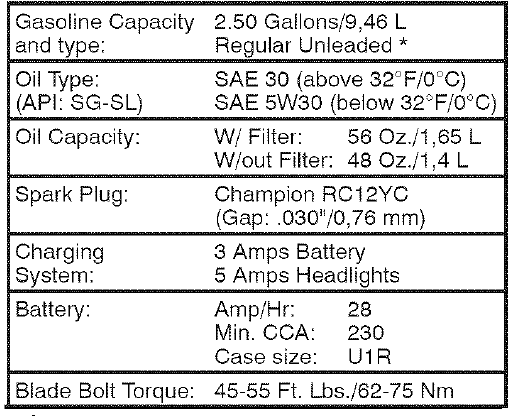
PRODUCT SPECIFICATIONS
UNASSEMBLED PARTS

ASSEMBLY PRE-OPERATION
Your new tractor has been assembled at the factory with exception of those parts left unassembled for shipping purposes.
TOOLS REQUIRED FOR ASSEMBLY
A socket wrench set will make assembly easier. Standard wrench sizes you need are listed below.
(1) 1/2″ wrench Tire pressure gauge
(2) 7/16″ wrenches Utility knife Pliers
When right or left hand is mentioned in this manual, it means when you are in the operating position (seated behind the steering wheel).
TO REMOVE TRACTOR FROM CARTON UNPACK CARTON
Remove all accessible loose parts and
- parts boxes from carton.
- Cut along dashed lines on all four panels of carton. Remove end panels and lay side panels flat.
- Check for any additional loose parts or cartons and remove.
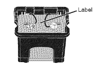
CHECK BATTERY
- Lift seat to raised position.

TO ADJUST SEAT
Grasp adjustment handle (A) and pull up, slide seat to desired position and release adjustment handle.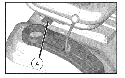
TO ROLL TRACTOR OFF SKID (See Operation section for location and function of controls)
- Raise attachment lift lever to its highest position.
- Release parking brake by depressing clutch/brake pedal.
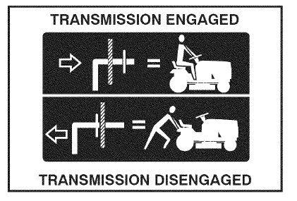
- Place freewheel control in “transmission disengaged position” (See “TO TRANSPORT” in Operation section of this manual).
- Roll tractor forward off skid.
- Remove banding holding the deflector shield up against tractor.
CHECK TIRE PRESSURE
The tires on your tractor were overinflated at the factory for shipping purposes. Correc tire pressure is important for best cutting performance.
- Reduce tire pressure to PSI shown on tires.
CHECK DECK LEVELNESS
For best cutting results, mower housing should be properly leveled. See “TO LEVEL MOWER” in th Service and Adjustments section of this manual.
CHECK FOR PROPER POSITION OF ALL BELTS
See the figures that are shown for replacing motion and mower blade drive belts in the Service an Adjustments section of this manual. Verify that the belts are routed correctly.
CHECK BRAKE SYSTEM
After you learn how to operate your tractor, check to see that the brake is operating properly. See “TO CHECK BRAKE” in the Service and Adjustments section of this manual.
OPERATION
These symbols may appear on your tractor or in literature supplied with the product. Learn and understand their meaning.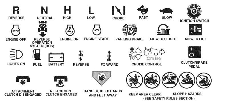
KNOW YOUR TRACTOR
READ THIS OWNER’S MANUAL AND SAFETY RULES BEFORE OPERATING YOUR TRACTOR
Compare the illustrations with your tractor to familiarize yourself with the locations of various controls and adjustments. Save this manual for future reference.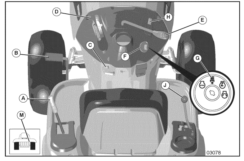
- (A) ATTACHMENT LIFT LEVER – Used to raise and lower the mower or other attachments mounted to your tractor.
- (B) CLUTCH/BRAKE PEDAL –Used for declutching and braking the tractor and starting the engine.
- (C) PARKING BRAKE- Locks clutch/brake pedal into the brake position.
- (D) THROTTLE/CHOKE CONTROL- Used for starting and controlling engine speed.
- (E) ATTACH M ENT CLUTCH LEVER –Used to engage the mower blades, or other attachments mounted to your tractor.
- (F) IGNITION SWITCH – Used for starting and stopping the engine.
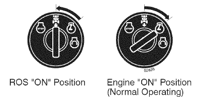
- (G) REVERSE OPERATION SYSTEM (ROS) “ON” POSITION – Allows operation of mower or other powered attachment while in reverse.
- (H) LIGHT SWITCH – Turns the headlights on and off.
- (J) MOTION CONTROL LEVER –Selects the speed and direction of tractor.
- (M) FREEWHEELCONTROL- Disengages transmission for pushing or slowly towing the tractor with the engine off.
HOW TO USE YOUR TRACTOR TO SET PARKING BRAKE
Your tractor is equipped with an operator presence sensing switch. When engine is running, any attempt by the operator to leave the seat without first setting the parking brake will shut off the engine.
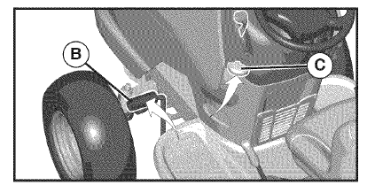
- Depress clutch/brake pedal (B) all the way down and hold.
- Pull parking brake lever (C) up and hold, release pressure from clutch/brake pedal (B), then release parking brake lever. Pedal should remain in brake position. Make sure parking brake will hold tractor secure.

TO MOVE FORWARD AND BACKWARD
The direction and speed of movement is controlled by the motion control lever. (J)
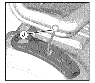
- Start tractor with motion control lever in neutral position.
- Release parking brake.
- Slowly move motion control lever to desired position.
TO ADJUST MOWER CUTTING HEIGHT
The position of the attachment lift lever (A) determines the cutting height.
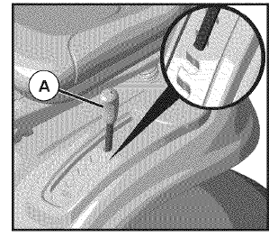
- Put attachment lift lever in desired cutting height slot. The cutting height range is approximately 1″ to 4″. The heights are measured from the ground to the blade tip with the engine not running. These heights are approximate and may vary depending upon soil conditions, height of grass and types of grass being mowed.
- The average lawn should be cut to approximately 2-1/2 inches during the cool season and to over 3 inches during hot months. For healthier and better looking lawns, mow often and after moderate growth.
- For best cutting performance, grass over 6 inches in height should be mowed twice. Make the first cut relatively high; the second to desired height.
TO OPERATE MOWER
Your tractor is equipped with an operator presence sensing switch. Any attempt by the operator to leave the seat with the engine running and the attachment clutch engaged will shut off the engine. You must remain fully and centrally positioned in the seat to prevent the engine from hesitating or cutting off when operating your equipment on rough, rolling terrain or hills.
- Select desired height of cut with attachment lift lever.
- Start mower blades by engaging attachment clutch control.
TO STOP MOWER BLADES – disengage attachment clutch control
TO TRANSPORT
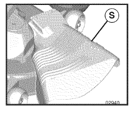
When pushing or towing your tractor, be sure to disengage transmission by placing freewheel control in freewheeling position. Freewheel control is located at the rear drawbar of tractor.
- Raise attachment lift lever to its highest position.
- Pull freewheel control out and into the slot and release so it is held in the disengaged position.
• Do not push or tow tractor at more than two (2) MPH.
• To re-engage transmission, reverse above procedure.
MOWING TIPS
- Tire chains cannot be used when the mower housing is attached to tractor.
- Mower should be properly leveled for best mowing performance. See “TO LEVEL MOWER HOUSING” in the Service and Adjustments section of this manual.
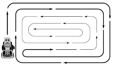
- The left hand side of mower should be used for trimming. Drive so that clippings are discharged onto the area that has already been cut. Have the cut area to the right of the tractor. This will result in a more even distribution of clippings and more uniform cutting.
- When mowing large areas, start by turning to the right so that clippings will discharge away from shrubs, fences, driveways, etc. After one or two rounds, mow in the opposite direction making left hand turns until finished.

- If grass is extremely tall, it should be mowed twice to reduce load and possible fire hazard from dried clippings. Make first cut relatively high; the second to the desired height.
- Do not mow grass when it is wet. We grass will plug mower and leave undesirable clumps. Allow grass to dry before mowing.
MAINTAINANCE
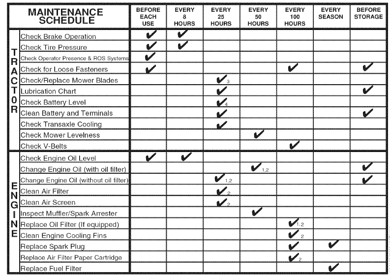
LUBRICATION CHART
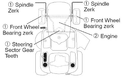
- General Purpose Grease
- Refer to Maintenance “ENGINE” Section
TRACTOR
Always observe safety rules when performing any maintenance.
BRAKE OPERATION
If tractor requires more than five (5) feet to stop at highest speed in highest gear on a level, dry concrete or paved surface, then brake must be serviced. (See “TO CHECK BRAKE” in the Service and Adjustments section of this manual).
TIRES
- Maintain proper air pressure in all tires (See the sides of tires for proper PSI).
- Keep tires free of gasoline, oil, or insect control chemicals which can harm rubber.
- Avoid stumps, stones, deep ruts, sharp objects and other hazards that may cause tire damage.
OPERATOR PRESENCE SYSTEM AND REVERSE OPERATION SYSTEM (ROS)
Be sure operator presence and reverse operation systems are working properly. If your tractor does not function as described, repair the problem immediately.
- The engine should not start unless the brake pedal is fully depressed, and the attachment clutch control is in the disengaged position.
CHECK OPERATOR PRESENCE SYSTEM
- When the engine is running, any attempt by the operator to leave the seat without first setting the parking brake should shut off the engine.
- When the engine is running and the attachment clutch is engaged, any attempt by the operator to leave the seat should shut off the engine.
- The attachment clutch should never operate unless the operator is in the seat.
BLADE REMOVAL
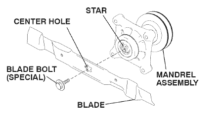
- Raise mower to highest position to allow access to blades.
- Remove blade bolt by turning counterclockwise.
- Install new blade with stamped “GRASS SIDE” facing the ground.
- Install and tighten blade bolt securely (45-55 Ft. Lbs. torque).

TO CHANGE ENGINE OIL
Determine temperature range expected before oil change. All oil must meet API service classification SG-SL
- Be sure tractor is on level surface.
- Oil will drain more freely when warm.
- Catch oil in a suitable container.
- Remove oil fill cap/dipstick. Be careful not to allow dirt to enter the engine when changing oil.
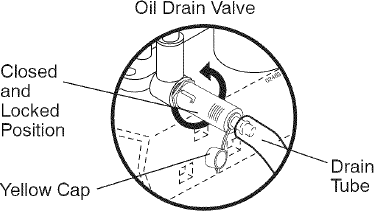
- Remove yellow cap from end of drain valve and install the drain tube onto the fitting.

- Unlock drain valve by pushing inward slightly and turning counterclockwise.
- To open, pull out on the drain valve.
- After oil has drained completely, dose and lock the drain valve by pushing inward and turning clockwise until the pin is in the locked position as shown.
- Remove the drain tube and replace the cap onto the end of the drain valve.
- Refill engine with oil through oil fill dipstick tube. Pour slowly. Do not overfill. For approximate capacity see “PRODUCT SPECI FICATIO NS” section of this manual.
- Use gauge on oil fill cap/dipstick for checking level. For accurate reading, insert dipstick into the tube and push down firmly into place before removing. Keep oil up to, but not over, the “FULL” line on dipstick. Push dipstick down firmly into the tube when finished.
AIR FILTER
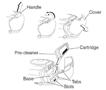
Your engine will not run properly using a dirty air filter. Replace pre-cleaner after every 25 hours of operation or every season. Service paper cartridge every 100 hours of operation or every season, whichever occurs first. Service air cleaner more often under dusty conditions.
- Pull up on air filter cover handle and rotate towards engine.
- Remove cover.
- Carefully remove air filter cartridge and pre-cleaner from base.
- Clean base carefully to prevent debris from falling into carburetor.

- Place new pre-cleaner and cartridge firmly in base.
- Align tabs on cover with slots in blower housing and replace cover.
- Hook handle on cover and push down on handle to close.
ENGINE COOLING SYSTEM
Debris may clog the engine’s air cooling system. Remove blower housing and clean area shown to prevent overheating and engine damage.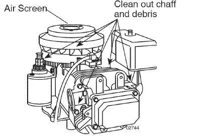
IN-LINE FUEL FILTER
The fuel filter should be replaced once each season, if fuel filter becomes clogged, obstructing fuel flow to carburetor, replacement is required.
- With engine cool, remove filter and plug fuel line sections.
- Place new fuel filter in position in fuel line with arrow pointing towards carburetor.
- Be sure there are no fuel line leaks and clamps are properly positioned.
- Immediately wipe up any spilled gasoline.

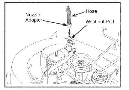
DECK WASHOUT PORT
Your tractor’s deck is equipped with a washout port on its surface as part of its deck wash system. It should be utilized after each use.
- Drive the tractor to a level, clear spot on your lawn, near enough to a water spigot for your garden hose to reach.
- Make sure the PTO (Blade Engage) is not engaged, set the parking brake, and stop the engine.
- Thread the nozzle adapter (packaged with your tractor’s Operator’s Manual) onto the end of your garden hose.
- Pull back the lock collar of the nozzle adapter and push the adapter onto the deck washout port at the left end of the mower deck. Release the lock collar to lock the adapter on the nozzle.

- Turn the water on.
- While sitting in the operator’s position on the tractor, re-start the engine and place the throttle lever in the Fast
 position.
 - Move the tractor’s PTO (Blade Engage) to the ON position. Remain in the operator’s position with the cutting deck engaged until the deck is cleaned.
- Move the tractor’s PTO (Blade Engage) to the OFF position. Turn the ignition key to the STOP position to turn the tractor’s engine off. Turn the water off.
- Pull back the lock collar of the nozzle adapter to disconnect the adapter from the nozzle washout port.
- Move the tractor to a dry area, preferably a concrete or paved area. Engage the mower deck PTO to remove excess water and to help dry before putting the tractor away.
TO REMOVE MOWER
- Place attachment clutch in “DISENGAGED” position.
- Lower attachment lift lever to its lowest position.
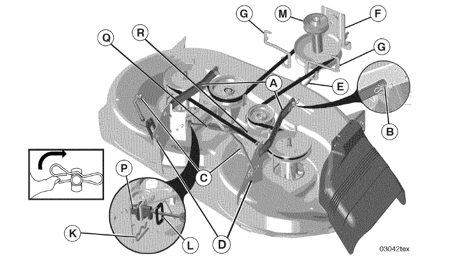
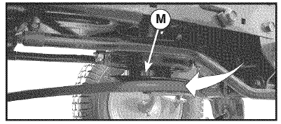
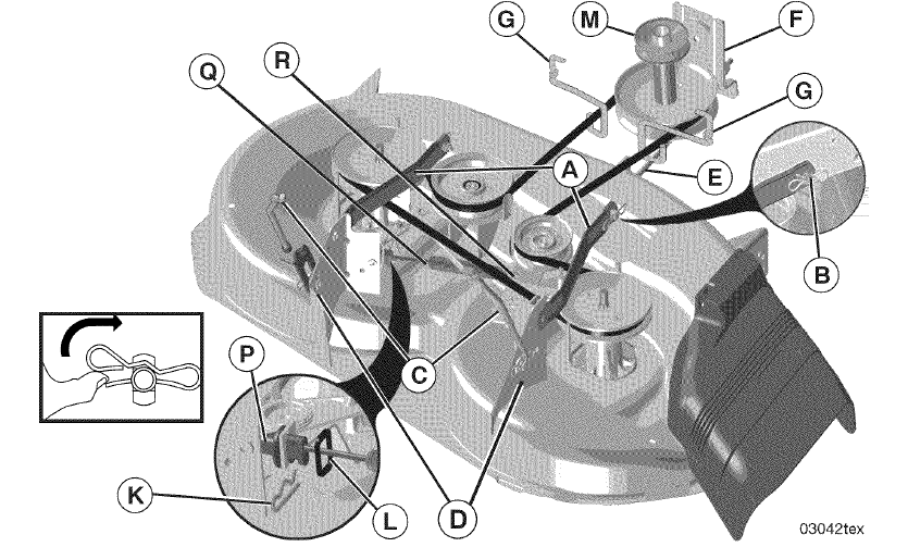
- Roll belt off engine pulley (M) and belt keepers (G).
- Remove retainer spring (K), slide collar (L) off and push housing guide (P) out of bracket.
- Remove clutch cable spring (Q) from idler arm (R).
- Disconnect front link (E) from mower -remove retainer spring and washer.
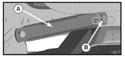
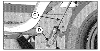
- Go to either side of mower and disconnect mower suspension arm (A) from chassis pin (B) and rear lift link (C) from rear mower bracket (D) – remove retainer springs and washers.
- Slide mower out from under right side of tractor.
TO INSTALL MOWER
Be sure tractor is on level surface and engage parking brake.
- Lower attachment lift lever to its lowest position.
- Slide mower under tractor until it is centered under tractor.

- ATTACH MOWER SIDE SUSPENSION ARMS (A) TO CHASSIS – Position hole in arm over pin (B) on outside of tractor chassis and secure with retainer spring.
- Repeat on opposite side of tractor.

- ATTACH REAR LIFT LINKS (C) – Lift rear corner of mower and position slot in link assembly over pin (D) on rear mower bracket and secure with washer and retainer spring.

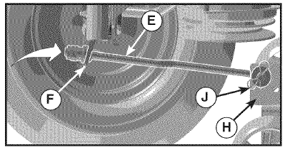
- ATTACH FRONT LINK (E) – Work from left side of tractor. Insert rod end of link assembly through front hole in tractor front suspension bracket (F).
- Insert end of link (E) into hole in front mower bracket (H) and secure with washer and retainer spring (J).

- Hook end of clutch cable spring (Q) into hole in idler arm (R).
- Push clutch cable housing guide (P) into bracket, slide collar (L) onto guide and secure with retainer spring (K).
- Install belt onto engine pulley (M) and belt keepers (G).

- Raise attachment lift lever to highest position.
- If necessary, adjust gauge wheels before operating mower as shown in the Operation section of this manual.

PRECISION SIDE-TO-SIDE ADJUSTMENT
- With all tires properly inflated, park tractor on level ground or driveway.
- Raise mower to its highest position.
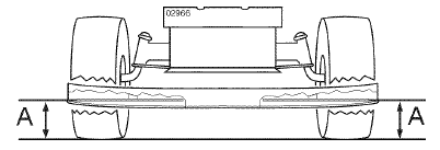
- At both sides of mower, position blade at side and measure the distance (A) from bottom edge of blade to the ground. The distance should be the same on both sides.

- If adjustment is necessary, see steps 2 and 3 in Visual Adjustment instructions above.
- Recheck measurements, adjust if necessary until both sides are equal.
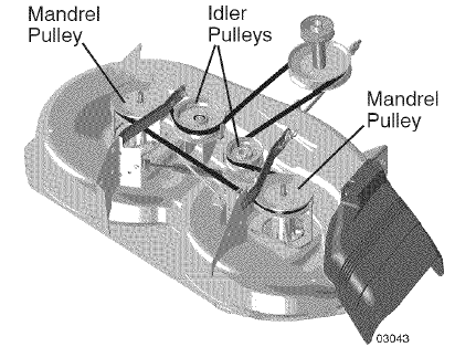
TO REPLACE MOWER BLADE DRIVE BELT
The mower blade drive belt may be replaced without tools. Park the tractor on level surface. Engage parking brake.
BELT REMOVAL
- Remove mower from tractor (See “TO REMOVE MOWER “in this section ofmanua0.
- Work belt off both mandrel pulleys and idler pulleys.
- Pull belt away from mower.
BELT INSTALLATION
- Work belt around both mandrel pulleys and idler pulleys
- Make sure belt is in all pulley grooves and inside all belt guides.
- Install mower (See “To Install Mower” in this section of this manual).

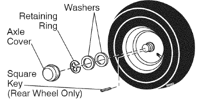
TO REMOVE WHEEL FOR REPAIRS
- Block up axle securely.
- Remove axle cover, retaining ring and washers to allow wheel removal (rear wheels have a square key – Do not lose).
- Repair tire and reassemble.
- Replace washers and snap retaining ring securely in axle groove.
- Replace axle cover.

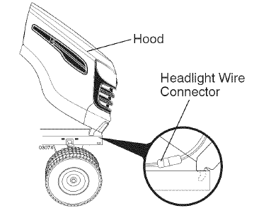
TO REMOVE HOOD & GRILL ASSEMBLY
- Raise hood.
- Unsnap headlight wire connector.
- Stand in front of tractor. Grasp hood at sides, tilt toward engine and lift off of tractor.
- When replacing hood, be sure to reconnect the headlight wire connector.

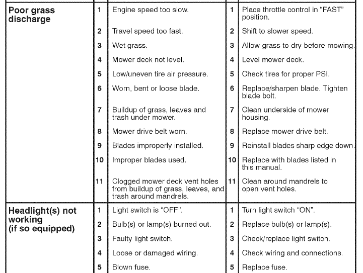
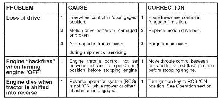
TROUBLESHOOTING CHART
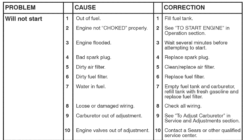
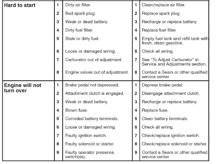
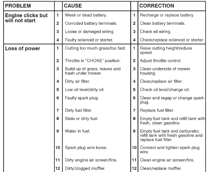
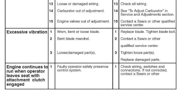
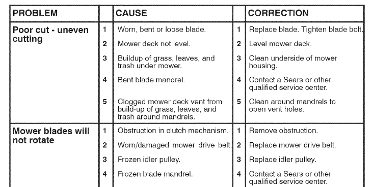

For more manuals by Craftsman visit, ManualsLibraryy
Craftsman 91720383 T2400 Lawn Mower-FAQs
How much oil does a Craftsman riding lawn mower take?
1. With filter: 56 oz.
2. Without filter: 48 oz.
How do you engage the blades on a Craftsman lawn mower?
Blades engage with a cable controlled by a lever. With the engine off, move the lever and check if the belt tightens properly or if it’s off a pulley or broken.
What is the lever on a lawn mower?
The lever, also called the blade control handle or brake bail arm, must be pressed and held down to start and run the engine. Releasing it stops the engine and blade.
How much oil does my lawn mower use?
Most walk or push mowers use 15–18 ounces of oil. Refer to your manual for the exact capacity of your mower model.
How do you level a lawn mower blade?
Measure the blade tips’ height on each side from the ground. Adjust the deck by loosening the hex bolt on the left hanger bracket. Once both blade tips are at the same height, tighten the bolt.
What is a PTO for a mower?
The PTO (Power Take-Off) belt drives the blades on a riding mower using the engine’s electric clutch system.
Which Craftsman mower do I have?
Flip the seat forward to locate the Product Identification Label under the seat. The model number starts with “CM.”
Who makes Craftsman mowers?
Craftsman mowers are manufactured by MTD under the Craftsman brand, which is owned by Stanley, Black & Decker.
How do I find my lawn mower part number?
Model numbers are located on the mower deck, frame, or under the seat for riding mowers.
What does SAE stand for in oil?
SAE stands for the Society of Automotive Engineers, which developed a classification system for oil viscosity based on temperature and performance.

