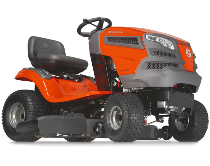
Husqvarna YTH150 Lawn Mower
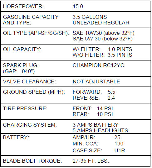
PRODUCT SPECIFICATIONS
ASSEMBLY
Your new tractor has been assembled at the factory with the exception of those parts left unassembled for shipping purposes. To ensure safe and proper operation of your tractor, all parts and hardware you assemble must be tightened securely. Use the correct tools as necessary to ensure proper tightness.
TOOLS REQUIRED FOR ASSEMBLY
A socket wrench set will make assembly easier. Standard wrench sizes are listed.
- (2) 7/16″ wrenches Phillips Screwdriver
- (2) 1/2″ wrenches Tire pressure gauge (2)
- 9/16″ wrenches Utility knife (1)
- 3/4″ socket with drive ratchet.
When right or left hand is mentioned in this manual, it means when you are in the operating position (seated behind the steering wheel).
TO REMOVE TRACTOR FROM CARTON
UNPACK CARTON
- Remove all accessible loose parts and parts cartons from carton (See page 5).
- Cut, from top to bottom, along lines on all four corners of carton, and lay panels flat.
- Check for any additional loose parts or cartons and remove.
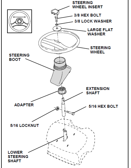
BEFORE ROLLING TRACTOR OFF SKID ATTACH STEERING WHEEL (See Fig. 1)
ASSEMBLE EXTENSION SHAFT AND BOOT
- Slide extension shaft onto lower steering shaft. Align mounting holes in extension and lower shafts and install 5/16 hex bolt and locknut. Tighten securely. IMPORTANT: TIGHTEN BOLT AND NUT SECURELY TO 18-22 FT. LBS TORQUE.
- Place tabs of steering boot over tab slots in dash and push down to secure.

INSTALL STEERING WHEEL
- Position front wheels of the tractor so they are pointing straight forward.
- Slide steering wheel adapter onto steering shaft extension.
- Position steering wheel so cross bars are horizontal (left to right) and slide inside boot and onto adapter.
- Assemble large flat washer, 3/8 lock washer, 3/8 hex bolt, and tighten securely.
- Snap steering wheel insert into center of steering wheel.
- Remove protective materials from tractor hood and grill.
TO ROLL TRACTOR OFF SKID (See Operation section for location and function of controls)
- Press lift lever plunger and raise attachment lift lever to its highest position.
- Release parking brake by depressing clutch/brake pedal.
- Place freewheel control in freewheeling position to disengage transmission (See “TO TRANSPORT” in the Operation section of this manual).
- Roll tractor backwards off skid.
- Remove banding, holding discharge guard up against tractor.
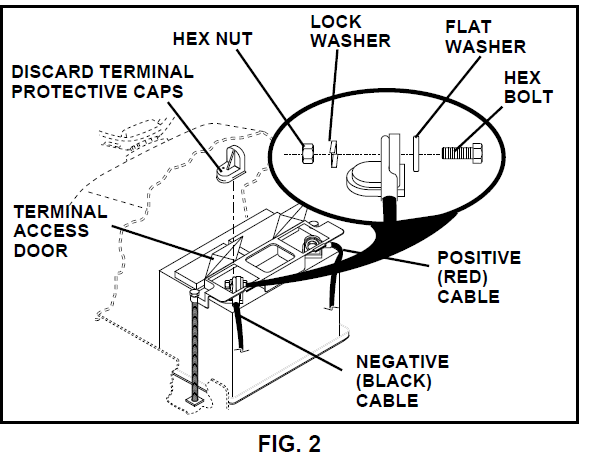
HOW TO SET UP YOUR TRACTOR CONNECT BATTERY (See Fig. 2)
- Lift hood to raised position.
- Open terminal access doors, remove terminal protective caps, and discard.
- If this battery is put into service after the month and year indicated on label (label located between terminals) charge the battery for a minimum of one hour at 6-10 amps.
- First connect RED battery cable to positive (+) battery terminal with hex bolt, flat washer, lock washer, and hex nut as shown. Tighten securely.
- Connect BLACK grounding cable to negative (-) battery terminal with remaining hex bolt, flat washer, lock washer, and hex nut. Tighten securely.
- Close terminal access doors.

Use terminal access doors for:
- Inspection for secure connections (to tighten hardware).
- Inspection for corrosion.
- Testing battery.
- Jumping (if required).
- Periodic charging.
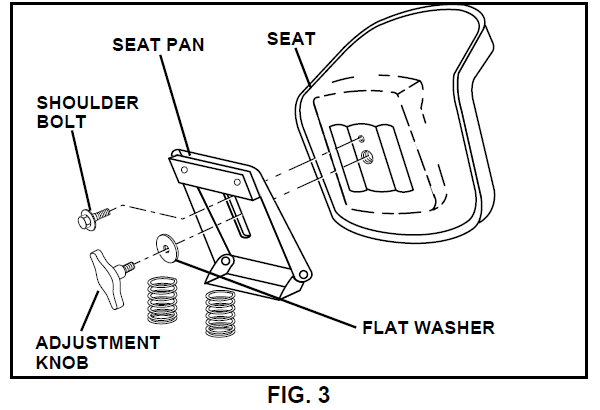
INSTALL SEAT (See Fig. 3)
Adjust seat before tightening adjustment knob.
- Remove cardboard packing on seat pan.
- Place seat on seat pan and assemble shoulder bolt. Tighten shoulder bolt securely.
- Assemble adjustment knob and flat washer loosely. Do not tighten.
- Lower seat into operating position and sit on seat.
- Slide seat until a comfortable position is reached which allows you to press clutch/brake pedal all the way down.
- Get off the seat without moving its adjusted position.
- Raise seat and tighten adjustment knob securely.

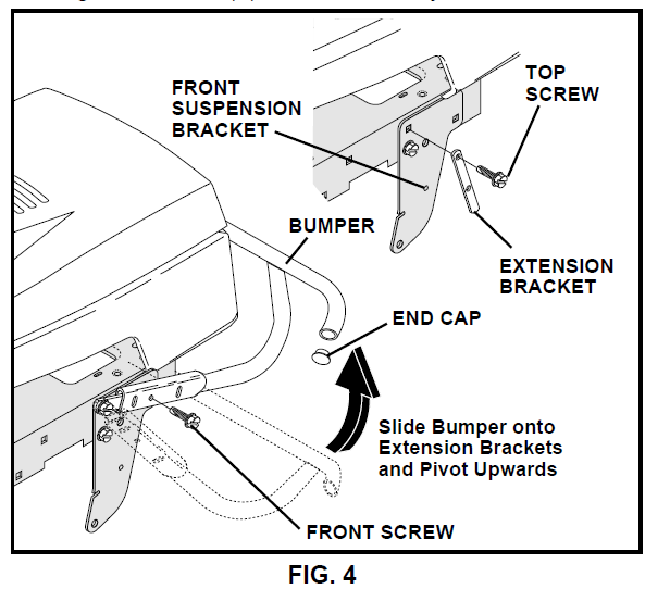
TO ATTACH FRONT BUMPER (See Fig. 4)
NOTE: For ease of assembly, you may wish to obtain the assistance of another person for mounting bumper to tractor.
- Press or tap the end caps into ends of bumper tube.
- The existing top screw and the existing front screw must be removed from both sides.
- On both sides of chassis, position extension bracket as shown and loosely assemble to rear chassis hole with supplied 3/8-16 x 1-1/4 screw. Do not tighten the brackets. Allow them to hang from the chassis.
- Position bumper and extension brackets so brackets can be slid inside flattened ends of bumper.
- Slide bumper onto brackets and pivot upwards to align center holes in extension brackets and tractor chassis.
- With holes aligned, install additional screws.
- Tighten all four (4) screws securely.

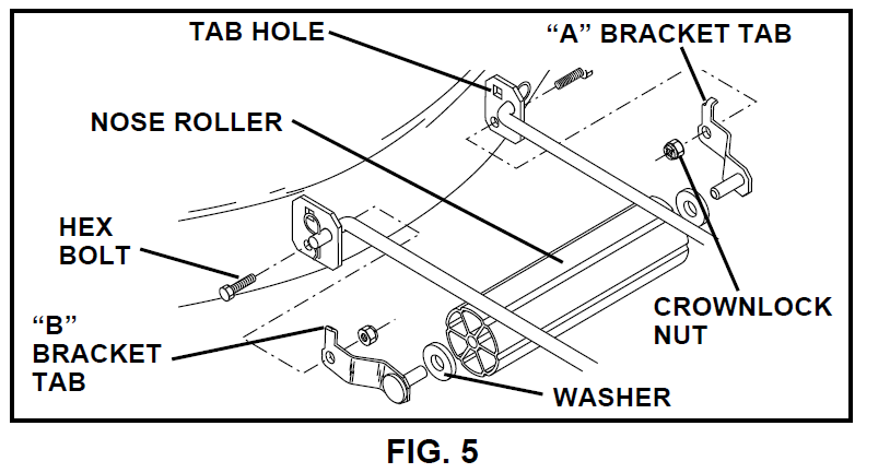
TO ATTACH NOSE ROLLER (See Fig. 5)
- Position brackets, 17/32 x 7/8 x 16 gauge washers, and nose roller between deck mounting brackets as shown. Be sure to position brackets on correct side, as shown.
- Install 3/8-16 x 1 hex bolts and 3/8-16 crownlock nuts as shown. Tighten hardware securely.

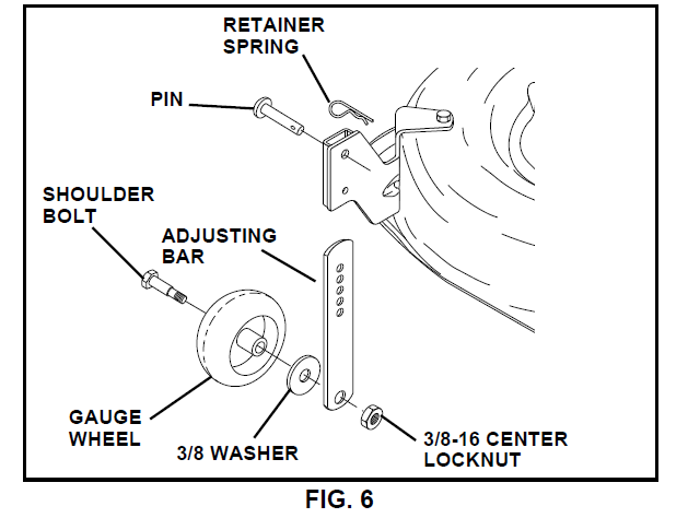
ASSEMBLE GAUGE WHEELS TO MOWER DECK (See Fig. 6)
The gauge wheels are designed to keep the mower deck in proper position when operating the mower. Be sure they are properly adjusted to ensure optimum mower performance.
- Slide gauge wheel bar down into bracket channel. Be sure that gauge wheel bar aligning holes are on top. Assemble gauge wheels as shown using shoulder bolts, 3/8 washers, and 3/8-16 center locknuts and tighten securely.
- Adjust gauge wheels before operating mower. See “TO ADJUST GAUGE WHEELS” in the Operation section of this manual.

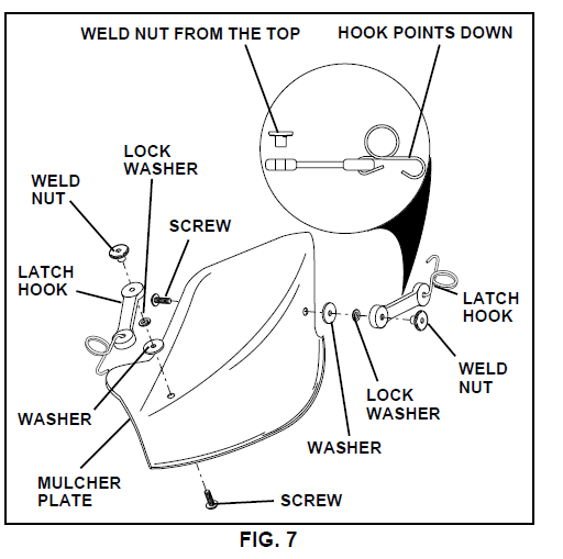
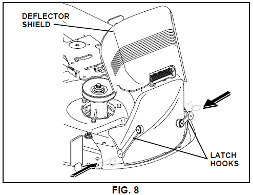
INSTALL MULCHER PLATE (See Figs. 7 and 8)
- Install two latch hooks to mulcher plate using screw, washer, lock washer, and weld nut as shown. NOTE: Pre-assemble weld nut to latch hook by inserting weld nut from the top with hook pointing down.
- Tighten hardware securely.
- Raise and hold deflector shield in upright position.
- Place front of mulcher plate over front of mower deck opening and slide into place, as shown.
- Hook front latch into hole on front of mower deck.
- Hook rear latch into hole on back of mower deck.


OPERATION
KNOW YOUR TRACTOR
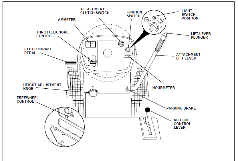
READ THIS OWNER’S MANUAL AND SAFETY RULES BEFORE OPERATING YOUR TRACTOR. Compare the illustrations with your tractor to familiarize yourself with the locations of various controls and adjustments. Save this manual for future reference.
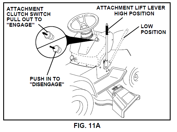
- ATTACHMENT CLUTCH SWITCH: Used to engage the mower blades, or other attachments mounted to your tractor.
- LIGHT SWITCH POSITION – Turns the headlights on.
- THROTTLE/CHOKE CONTROL: Used for starting and controlling engine speed.
- FREE WHEEL CONTROL – Disengages transmission for pushing or slowly towing the tractor with the engine off.
- CLUTCH/BRAKE PEDAL – Used for declutching and braking the tractor and starting the engine.
- HOURMETER – Indicates hours of operation.
- HEIGHT ADJUSTMENT KNOB – Used to adjust the mower cutting height.
- AMMETER – Indicates charging (+) or discharging (-) of battery.
- PARKING BRAKE – Locks clutch/brake pedal into the brake position.
- MOTION CONTROL LEVER – Selects the speed and direction of tractor.
- ATTACHMENT LIFT LEVER – Used to raise and lower the mower deck or other attachments mounted to your tractor.
- LIFT LEVER PLUNGER – Used to release attachment lift lever when changing its position.
- IGNITION SWITCH – Used for starting and stopping the engine.

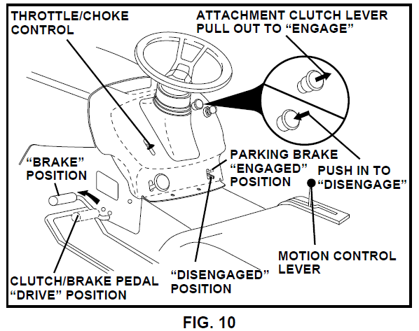
HOW TO USE YOUR TRACTOR TO SET PARKING BRAKE (See Fig. 10)
Your tractor is equipped with an operator presence sensing switch. When the engine is running, any attempt by the operator to leave the seat without first setting the parking brake will shut off the engine.
- Depress clutch/brake pedal into full “BRAKE” position and hold.
- Place parking brake lever in “ENGAGED” position and release pressure from clutch/brake pedal. Pedal should remain in “BRAKE” position. Make sure parking brake will hold tractor secure.

STOPPING (See Fig. 10)
MOWER BLADES –
- Move attachment clutch switch to “DISENGAGED” position.
GROUND DRIVE –
- Depress clutch/brake pedal into full “BRAKE” position.
- Move motion control lever to neutral (N) position. IMPORTANT: THE MOTION CONTROL LEVER DOES NOT RETURN TO NEUTRAL (N) POSITION WHEN THE CLUTCH/BRAKE PEDAL IS DEPRESSED.
ENGINE –
- Move throttle control to slow position.
TO USE THROTTLE CONTROL (See Fig. 10)
Always operate engine at full throttle.
- Operating engine at less than full throttle reduces the battery charging rate.
- Full throttle offers the best bagging and mower performance.
TO MOVE FORWARD AND BACKWARD (See Fig. 10)
The direction and speed of movement are controlled by the motion control lever.
- Start tractor with motion control lever in neutral (N) position.
- Release parking brake and clutch/brake pedal.
- Slowly move motion control lever to desired position.
TO ADJUST MOWER CUTTING HEIGHT (See Fig. 10)
The cutting height is controlled by turning the height adjustment knob in the desired direction.
- Turn knob clockwise
 to raise cutting height.
 - Turn knob counterclockwise
 to lower cutting height. The cutting height range is approximately 1-1/2″ to 4″. The heights are measured from the ground to the blade tip with the engine not running. These heights are approximate and may vary depending upon soil conditions, height of grass, and types of grass being mowed.
 - The average lawn should be cut to approximately 2-1/2 inches during the cool season and to over 3 inches during hot months. For healthier and better-looking lawns, mow often and after moderate growth.
- For best cutting performance, grass over 6 inches in height should be mowed twice. Make the first cut relatively high; the second to desired height.
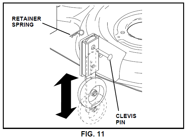
TO ADJUST GAUGE WHEELS (See Fig. 11)
Gauge wheels are properly adjusted when they are slightly off the ground when the mower is at the desired cutting height in operating position. Gauge wheels then keep the deck in proper position to help prevent scalping in most terrain conditions.
- Be sure tractor is on a flat level surface.
- Lower mower and adjust mower to desired cutting height.
- Remove retainer spring and clevis pin, which secure each gauge wheel bar.
- Lower gauge wheels to ground. Raise gauge wheels slightly to align holes in bracket and gauge wheel bar and insert clevis pin. Gauge wheels should be slightly off the ground.
- Replace retainer spring into clevis pin.

TO OPERATE MOWER (See Fig. 11A)
Your tractor is equipped with an operator presence sensing switch. Any attempt by the operator to leave the seat with the engine running and the attachment clutch engaged will shut off the engine.
- Select desired height of cut.
- Lower mower with attachment lift control.
- Start mower blades by engaging attachment clutch control.
- TO STOP MOWER BLADES – disengage attachment clutch control.

TO OPERATE ON HILLS
- Choose the slowest speed before starting up or down hills.
- Avoid stopping or changing speed on hills.
- If slowing is necessary, move throttle control lever to slower position.
- If stopping is absolutely necessary, push clutch/brake pedal quickly to brake position and engage parking brake.
- Move motion control lever to neutral (N) position.
IMPORTANT: THE MOTION CONTROL LEVER DOES NOT RETURN TO NEUTRAL (N) POSITION WHEN THE CLUTCH/BRAKE PEDAL IS DEPRESSED.
- To restart movement, slowly release parking brake and clutch/brake pedal.
- Slowly move motion control lever to slowest setting.
- Make all turns slowly.
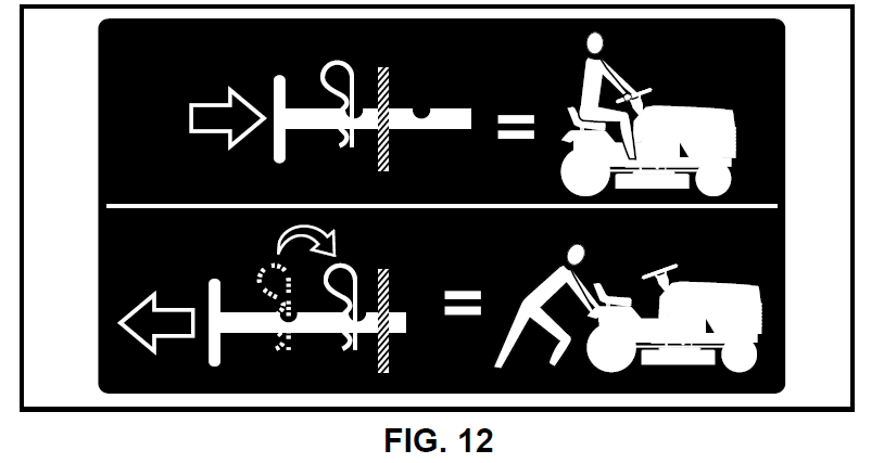
TO TRANSPORT (See Figs. 9 and 12)
When pushing or towing your tractor, be sure to disengage transmission by placing freewheel control in freewheeling position. Free wheel control is located at the rear drawbar of the tractor.
- Raise attachment lift to highest position with attachment lift control.
- Pull freewheel control knob out and hold in position by inserting retainer spring into forward hole of control rod.
- Do not push or tow tractor at more than two (2) MPH.
- To reengage transmission, reverse above procedure. NOTE: To protect hood from damage when transporting your tractor on a truck or a trailer, be sure hood is closed and secured to tractor. Use an appropriate means of tying hood to tractor (rope, cord, etc.).

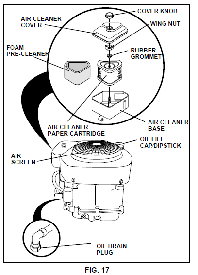
BEFORE STARTING THE ENGINE CHECK ENGINE OIL LEVEL (See Fig. 17)
- The engine in your tractor has been shipped, from the factory, already filled with summer weight oil.
- Check engine oil with tractor on level ground.
- Unthread and remove oil fill cap/dipstick; wipe oil off. Reinsert the dipstick into the tube and rest the oil fill cap on the tube. Do not thread the cap onto the tube. Remove and read oil level. If necessary, add oil until “FULL” mark on dipstick is reached. Do not overfill.
- For cold weather operation, you should change oil for easier starting (See “OIL VISCOSITY CHART” in the Customer Responsibilities section of this manual).
- To change engine oil, see the Customer Responsibilities section in this manual.

ADD GASOLINE
- Fill fuel tank. Use fresh, clean, regular unleaded gasoline with a minimum of 87 octane. (Use of leaded gasoline will increase carbon and lead oxide deposits and reduce valve life.). Do not mix oil with gasoline. Purchase fuel in quantities that can be used within 30 days to assure fuel freshness.
- IMPORTANT: WHEN OPERATING IN TEMPERATURES BELOW 32°F(0°C), USE FRESH, CLEAN WINTER GRADE GASOLINE TO HELP INSURE GOOD COLD WEATHER STARTING.
TO START ENGINE (See Fig. 10)
When starting the engine for the first time or if the engine has run out of fuel, it will take extra cranking time to move fuel from the tank to the engine.
- Be sure freewheel control is in the transmission engaged position.
- Sit on seat in operating position, depress clutch/brake pedal, and set parking brake.
- Place motion control lever in neutral (N) position.
- Move attachment clutch to “DISENGAGED” position.
- Move throttle control to choke position. Note: Before starting, read the warm and cold starting procedures below.
- Insert key into ignition and turn key clockwise to “START” position and release key as soon as engine starts. Do not run starter continuously for more than fifteen seconds per minute. If the engine does not start after several attempts, move throttle control to fast position, wait a few minutes, and try again. If engine still does not start, move the throttle control back to the choke position and retry.
WARM WEATHER STARTING (50° F and above)
- When engine starts, move the throttle control to the fast position. The attachments and ground drive can now be used. If the engine does not accept the load, restart the engine and allow it to warm up for one minute using the choke as described above.
COLD WEATHER STARTING (50° F and below)
- When the engine starts, allow the engine to run with the throttle control in the choke position until the engine runs roughly, then move the throttle control to the fast position. This may require an engine warm-up period from several seconds to several minutes, depending on the temperature.
HYDROSTATIC TRANSMISSION WARM UP
- Before driving the unit in cold weather, the transmission should be warmed up as follows:
- Be sure the tractor is on level ground.
- Place the motion control lever in neutral. Release the parking brake and let the clutch/brake slowly return to operating position.
- Allow one minute for transmission to warm up. This can be done during the engine warm-up period.
- The attachments can also be used during the engine warm-up.
PURGE TRANSMISSION
To ensure proper operation and performance, it is recommended that the transmission be purged before operating the tractor for the first time. This procedure will remove any trapped air inside the transmission, which may have developed during shipping of your tractor.
- Place tractor safely on level surface with engine off and parking brake set.
- Disengage transmission by placing freewheel control in freewheeling position (See “TO TRANSPORT” in this section of manual).
- Sitting in the tractor seat, start engine. After the engine is running, move throttle control to slow position. With motion control lever in neutral (N) position, slowly disengage clutch/brake pedal.
- Move motion control lever to full forward position and hold for five (5) seconds. Move lever to full reverse position and hold for five (5) seconds. Repeat this procedure three (3) times. NOTE: During this procedure, there will be no movement of drive wheels. The air is being removed from the hydraulic drive system.
- Move motion control lever to neutral (N) position. Shut off engine and set parking brake.
- Engage transmission by placing freewheel control in driving position (See “TO TRANSPORT” in this section of manual).
- Sitting in the tractor seat, start engine. After the engine is running, move throttle control to half (1/2) speed. With motion control lever in neutral (N) position, slowly disengage clutch/brake pedal.
- Slowly move motion control lever forward. After the tractor moves approximately five (5) feet, slowly move the motion control lever to reverse position. After the tractor moves approximately five (5) feet, return the motion control lever to the neutral (N) position. Repeat this procedure with the motion control lever three (3) times.
- Your tractor is now purged and now ready for normal operation.
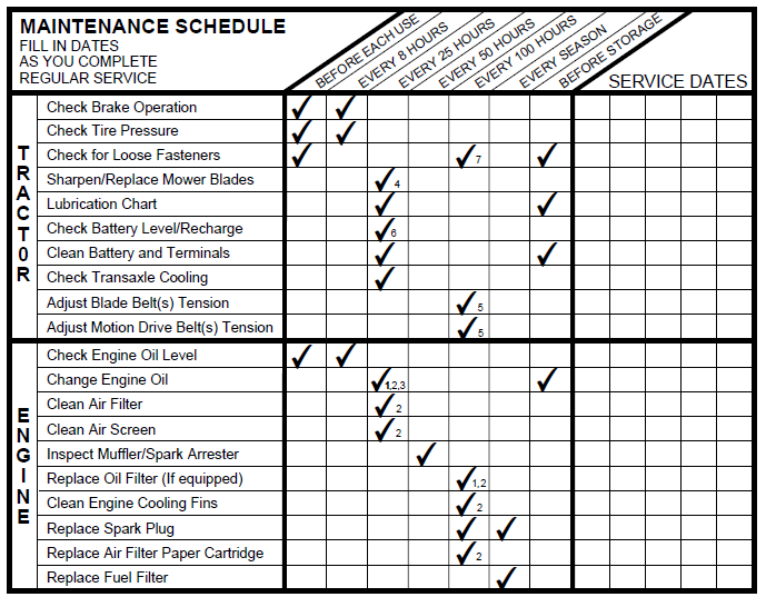
CUSTOMER RESPONSIBILITIES
- Change more often when operating under a heavy load or in high ambient temperatures.
- Service more often when operating in dirty or dusty conditions.
- If equipped with oil filter, change oil every 50 hours.
- Replace blades more often when mowing in sandy soil.
- If equipped with an adjustable system.
- Not required if equipped with maintenance-free battery.
- Tighten front axle pivot bolt to 35 ft.-lbs. maximum. Do not overtighten.

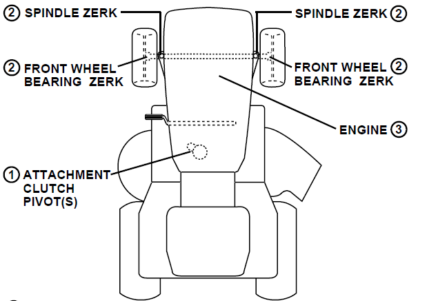
LUBRICATION CHART
- SAE 30 OR 10W30 MOTOR OIL
- GENERAL PURPOSE GREASE
- REFER TO CUSTOMER RESPONSIBILITIES “ENGINE” SECTION

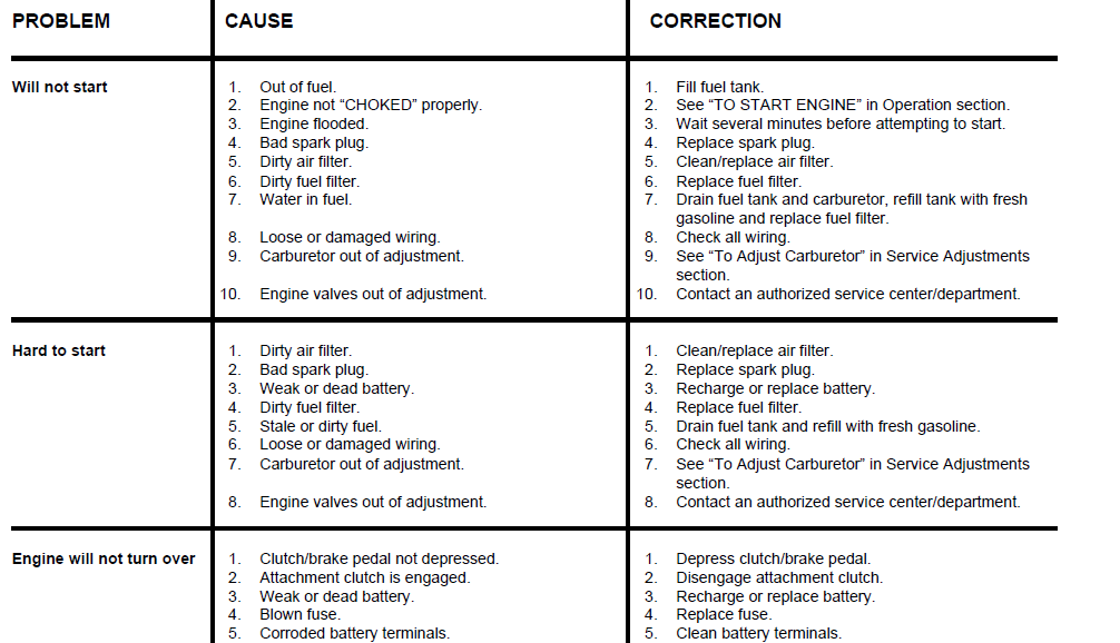
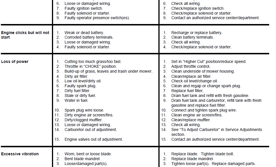
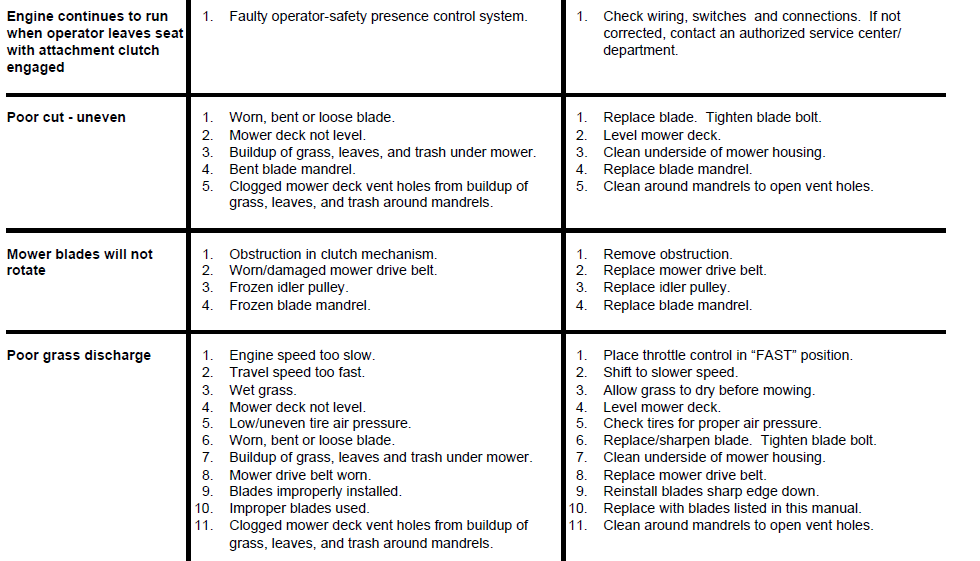
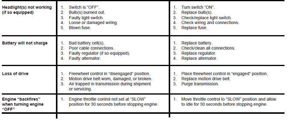
TROUBLESHOOTING POINTS
For More Manuals By Husqvarna, Visit ManualsLibraryy.
Husqvarna YTH150 Lawn Mower-FAQs.
Q1. What are the most common problems with Husqvarna riding mowers?
The most common issues include difficulty starting, stalling after starting, battery draining, gas leakage, lack of self-propulsion, and smoking during use.
Q2. How do I find the model and serial number of my Husqvarna mower?
The model and serial number tag is usually located on the frame near the left rear wheel, inside the right fender, or under the seat.
Q3. Are Husqvarna mower tires tubeless?
Yes, most Husqvarna mowers come with tubeless tires. A tire sealant can be used if leaks occur.
Q4. What type of oil should I use in a Husqvarna riding mower?
Husqvarna recommends full synthetic 10W-30 4-stroke engine oil for reliable performance and durability.
Q5. How often should I change the oil in my Husqvarna riding mower?
Change the oil after every 50 hours of use or at least once per season. Always check oil levels before mowing.
Q6. Can I use 5W-30 instead of 10W-30 in my mower?
Yes. Both are 30-weight oils at operating temperature. 5W-30 performs better in cold conditions, making it easier to start.
Q7. How do I check the oil level in my Husqvarna mower?
Remove the dipstick cap, wipe it clean, reinsert it fully, then check the oil level. Add oil if it’s below the recommended mark.
Q8. How many hours can a Husqvarna riding mower last?
With proper care, it typically lasts around 600–800 hours. Occasional-use mowers can last over 1,000 hours.
Q9. Do Husqvarna riding mowers have power steering?
Some advanced models, like the AWD series, come equipped with power steering for easier handling on rough or hilly terrain.

