![]()
Kaba Simplex 1000 Series Door Lock
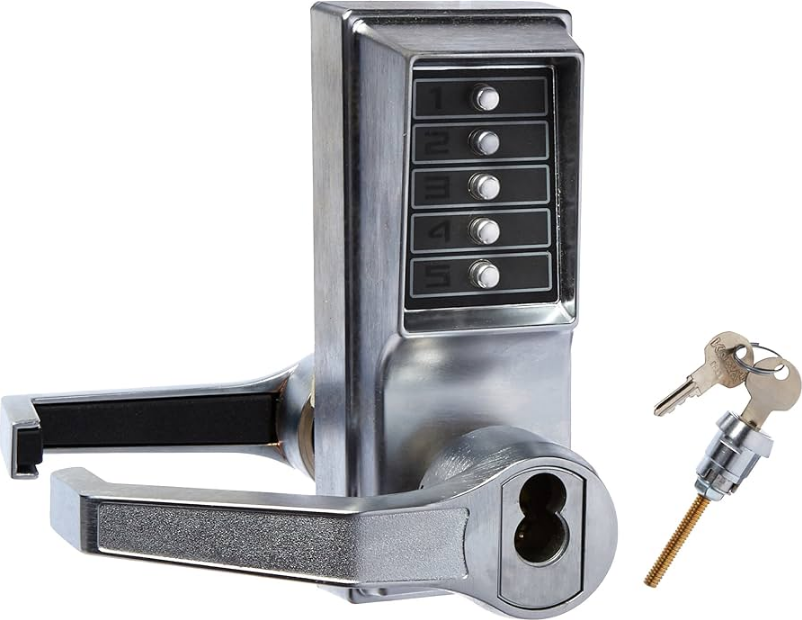
Tools required:
- Electric drill (variable speed)
- Awl or center punch
- 218″ (54 mm) Hole saw with pilot drill
- 1″ (25 mm) Hole saw with pilot drill
- 1⁄4″ (6 mm) Drill bit
- 1″ (25 mm) Wood chisel
- Hammer
- Phillips head screwdriver
- Small flat-blade screwdriver
- Pliers (2) for passage set locks only
Marking the door
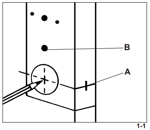
The door-to-frame relationship is crucial for the latch mechanism’s performance. The vertical and horizontal center lines are crucial when positioning the lock, strike, and latch, and all must adhere to ANSI standard A115.2.
- Fold the paper template (found in the middle of this booklet) on the line as indicated.
- Tape the template securely to the door so that all the indicated folds are properly aligned with the high beveled edge of the door.
- Mark the door using a center punch as indicated on the template. Models 101x and 102x without the passage feature
require 5 holes; models 103x, 104x, with passage feature require 6 holes (B) (see figure 1-1). - Remove the template.
Drilling the holes
- Use a hole saw with a pilot drill bit to drill the 21⁄8″ (54 mm) hole: apply pressure evenly until the circular blade cuts the first side of the door and the tip of the pilot bit emerges through the other side, then stop.
- Drill through the other side of the door until the 21⁄8″ (54 mm) circular hole is completed.
- Use a hole saw with a pilot drill bit to drill the 1″ (25 mm) hole in the door face. Passage feature models require an additional 1″ (25 mm) hole in the door face (see A in Figure 2-1) (repeat the same drilling procedure as before).
- Use a standard drill bit to drill the two 1⁄4″ (6 mm) holes for the mounting screws.
- Drill the final 1″ (25 mm) hole for the latch through the edge of the door. Drill until the hole saw is visible through the 21 ⁄8″ (54
mm) hole, then stop (see Figure 2-1).
Installing the latch

- Insert the latch into the 1″ (25 mm) hole until the face plate butts up against the door edge. Make sure the bevel of the latch bolt faces the same direction as the door swings to close (A) (see Figure 3-1).
- Draw a line around the face plate, then remove the latch. Use a sharp 1″ (25 mm) wood chisel to remove approximately 1 ⁄8″ (3 mm) of material or enough so the face plate is perfectly flush with the edge of the door (see Figure 3-1).
- Insert the latch into the 1″ (25 mm) hole in the door edge until the latch face plate is flush with the door edge (see Figure 3-2)
- Secure the latch to the door with two of the 3⁄4″ (19 mm) screws provided (item “j” on checklist).
Adjusting the lock
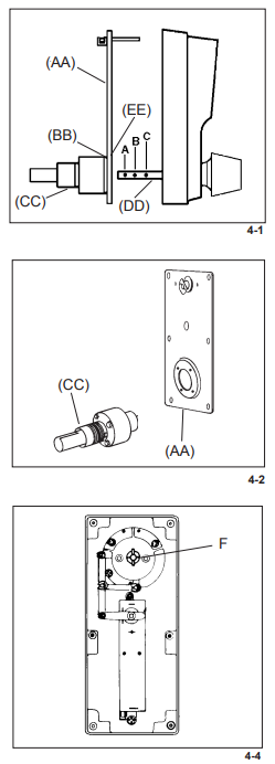
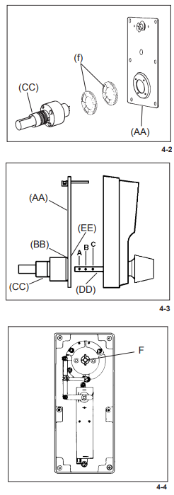
13⁄8″ (35 mm) to 11⁄2″ (38 mm) 4a The 1000 Series lockset has been preassembled at the factory to accommodate doors 15⁄8″ (41 mm) to 17⁄8″ (48 mm) thick. For doors 13⁄8″ (35 mm) to 11⁄2″ (38 mm) thick, adjust the lock as follows: (see figures 4-1 and 4-2)
- Remove the back plate assembly (AA) by removing the six back plate screws. One of the screws may be under the
serial number sticker. - Remove the cylindrical drive unit (CC) from the back plate assembly (AA) by removing the four Phillips head seems screws (EE) from the underside of the back plate (AA).
- Remove (and discard) the spacer (BB) located between the back plate assembly (AA) and the cylindrical drive unit (CC).
- Remount the cylindrical drive unit (CC) onto the back plate assembly (AA) using the four 8-32 x 3⁄16 (5 mm) shorter Phillips head sems screws provided (item “k” from the checklist).
- Remove the cross pin from position B on the drive shaft (DD).
- Reposition the cross pin in position C on the drive shaft (DD).
- Reinstall the back plate assembly (AA) onto the front lock case.
Adjusting the lock 2″ (51 mm) to 21⁄4″ (57 mm). For doors 2″ (51 mm) t o 21⁄4″ (57 mm)
thick, adjust the lock as follows: (see figures 4-2 & 4-3)
- Remove the back plate assembly (AA) by removing the six back plate screws. One of the screws may be under the serial number sticker.
- Remove the cylindrical drive unit (CC) from the back plate assembly (AA) by removing the four Phillips head seems screws (EE) from the underside of the back plate.
- Insert the extra spacer provided in the accessory pack (item “f” on the checklist) between the cylindrical drive unit (CC) and the back plate assembly (AA).
- Remount the cylindrical drive unit (CC) onto the back plate assembly (AA) using the four 8-32 x 11⁄16″ (17 mm) Phillips
head sems screws provided (item “l” on checklist). - Add a cross pin (item “h” on the checklist) in position A on the drive shaft (DD) (see Figure 4-3).
- Remount the back plate assembly (AA) onto the front lock housing.
Changing the handle of the lock

- Remove the back plate assembly (A) from the front lock housing by removing the six back plate sems screws (see Figure 5-2).
- Unscrew the four Phillips head seems screws (B) and remove the cylindrical drive unit (C) from the back plate (A).
- Turn the cylindrical drive unit (C) 180° so that the cutout for the latch (D) faces the opposite direction.
- Reattach the cylindrical drive unit (C) to the back plate assembly (A) using the four Phillips head screws removed in
step 2. - Remount the back plate assembly (A) onto the front lock housing assembly.
- Tighten all six screws securely.
- Test the lock to make sure it is still working properly (see “Testing the operation of the lock” on page 16).
Installing the lock
- Remove the inside knob by using the pointed end of the spanner wrench (item “i” on the checklist) to depress the spring
loaded retaining clip, visible through the poke hole in the collar of the cylindrical drive unit. - Pull the knob while simultaneously releasing the retaining clip.
- Remove the knob from the lock body.
- Align the latch tailpiece (A) with the shoe retractor (B) of the cylindrical drive unit (D) by depressing the latch bolt slightly. Make sure that the latch prongs (C) and cylindrical drive unit (D) engage each other as shown in Figure 6-1.
Testing the operation of the lock
- Enter the factory-set combination: Depress buttons 2 and 4 at the same time (release), then depress button 3 (release). You should feel a slight click as each button is depressed (see figure
7-1). - Turn the outside knob clockwise to the stop position and hold. Make sure the latch is fully retracted and flush with the latch face plate.
- Release the knob. The latch should return to the fully extended position.
- Turn the inside drive sleeve (A) to the left to the stop position and hold (see Figure 7-2). The latch will retract until it is flush
with the latch face plate. Release the sleeve — the latch should return to the fully extended position. Repeat by turning the sleeve to the right.
Installing the reinforcing plate
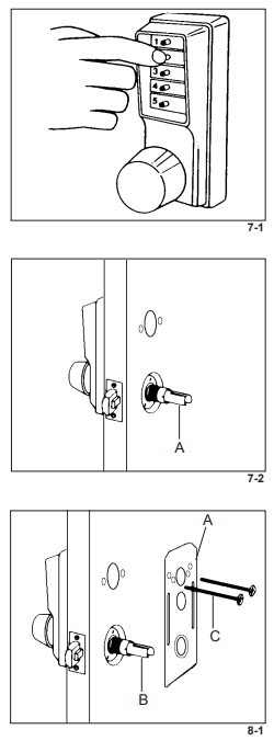
- Place the reinforcing plate (A) over the inside drive sleeve (B) as shown in Figure 8-1.
- Insert the two 21⁄2″ (64 mm) screws (C) (item “m” on the checklist) through the reinforcing plate into the 1⁄4″ (6 mm) holes drilled in the door.
- Tighten the screws to secure the lock housing to the door. The reinforcing plate (A) should be parallel to the edge of the door and centered around the inside drive sleeve (B).
Installing the passage set models 103x, 104x
- Insert the key or turn knob passage set assembly (A) into the lower opening in the trim plate (C) and secure it with the
spring clip (B) from inside (see Figure 9-1). - The tailpiece (D) is scored in several places so you can easily break off the section that extends beyond the required length to engage the passage set cam.
- Hold the tailpiece (D) firmly with a pair of pliers on the passage plug side of the tailpiece, adjacent to the desired break line.
- With a second pair of pliers, grip the tailpiece on the other side of the scored line and bend up and down until it breaks (see Figure 9-2).
Installing the inside trim plate

- Position the trim plate (A) over the reinforcing plate (B) (see Figure 10-1). For passage models, ensure the tailpiece is aligned with the passage actuator slot, and the two engage properly.
- Gently screw the thread ring (C) clockwise onto the cylindrical drive unit (D). If you encounter difficulty during Step 2, remove the trim plate and readjust the reinforcing plate. Do not force the thread ring.
- Tighten the thread ring (C) clockwise using the spanner wrench provided (E) (item “i” on the checklist) (see Figure 10-2).
Installing the inside knob
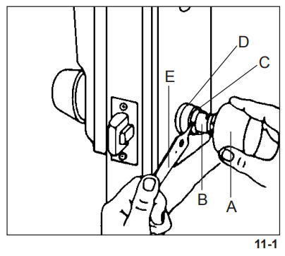
- Place the knob (A) on the inside drive sleeve (B). Locate the retaining clip through the poke hole in the collar (C) of the inside drive sleeve (B). If the thread ring (D) covers this poke hole, loosen the thread ring and align the hole in the thread ring with the hole in the collar (C).
- Depress the knob-retaining clip using the pointed tip of the spanner wrench (E) (see Figure 11-1).
- Push the inside knob on while simultaneously removing the spanner wrench (E) — The retaining clip will snap back
into place securing the knob. - Retighten the thread ring if it was loosened.
- Turn the inside knob to the left to the stop position and hold. The latch should retract smoothly until it is flush with the face plate. Repeat by turning the knob to the right.
- Release the knob — the latch should return to the fully extended position.
Installing the combination change plug assembly
- Insert the DF-59 key (A) into the cylinder (B) of the combination change plug assembly (see Figure 12-1).
- Insert the threaded bolt (C) through the hole in the trim plate and into the mounting stud located in the 1″ (25 mm) diameter cutout (see Figure 12-1). No spring clip is required.
- Turn the key clockwise until the collar of the combination change plugs assembly butts up to the trim plate.
Troubleshooting
- The outside knob when turned always retracts the latch without depressing any buttons.
- The lock is in zero combination.
- Follow the procedure for changing a combination except omit step 3 (do not enter the existing combination).
- The threaded rod from the combination change assembly remains in the lock after it is removed.
- The combination change assembly was over-tightened when put on the door.
- If necessary, remove the lock from the door. Using a vice-grip wrench, turn at the middle of the rod (to avoid stripping the active threads), and turn counterclockwise to remove the rod from the lock. Put the rod back into the control lock and tighten the spring nut.
- Remove the lock on the door.
- After entering a new combination, the lock works one time only; then the lock fails to open.
- Buttons of the intended combination were not fully depressed when changing the combination.
- Refer to “Reset an Unknown Combination” on pages 38 & 40.
- Correct code is depressed, the outside knob turns about 10 degrees and the latch partially retracts then jams. Key override in outside knob cannot retract the latch. The inside knob cannot retract the latch.
- The dead latch is wedged into the strike box, caused by improper door, door stop, and strike plate alignment. Saw or break the latch to gain access or to get out. Replace the latch and adjust the door/frame alignment to prevent a similar
occurrence. - If the outside knob was forced to retract the latch, the chamber control shaft may have twisted. Replace the chamber
FOR MORE MANUALS BY DORMAKABA, VISIT MANUALSLIBRARYY
Kaba Simplex 1000 Series Door Lock-FAQs
How does a Kaba Simplex lock work?
Users enter a pre-set numeric code on the push-button keypad.
The lock mechanically verifies the code and releases the latch.
No electricity or batteries are required.
What is the default factory code for Kaba Simplex locks?
The default code is usually:
Press 2 and 4 together, then
Press 3.
How do I change the code on a Kaba Simplex 1000 lock?
Enter the current combination.
Turn the knob clockwise to unlock.
Press and hold the “Program” button (if applicable).
Enter the new code, then confirm.
Test the new code to ensure it works.
(Refer to the user manual for model-specific steps.)
Can Kaba Simplex locks be used on exterior doors?
Yes, they are weather-resistant and suitable for exterior, interior, and security doors.
Why is my Kaba lock blinking red?
Low battery (if electronic).
Failed access attempt.
System error (check manual for troubleshooting).
How many combinations are possible with a Simplex lock?
A 5-button Simplex lock has 1,082 possible combinations.
Are Kaba Simplex locks secure?
Yes, they offer:
No keys (prevents duplication).
No electronics (works without power).
Durable construction (vandal-resistant options available).

 o 21⁄4″ (57 mm)