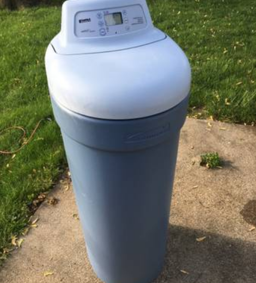
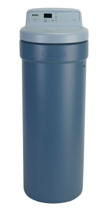
Kenmore 300 Series Water Softener
PARTS DESCRIPTIONS
SMALL PARTS
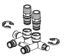
Installation Adaptors (2)
Drain Tubing
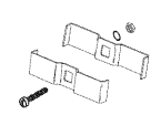
Ground Clamp Kit
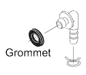
Tube Adaptor
![]()
Tube Clamp
PLAN YOUR INSTALLATION
It is recommended to read through the entire manual before beginning your installation. Follow all steps exactly. Reading this manual will also help you get all the benefits from your system.
TOOLS NEEDED:
- Safety glasses
- Flathead screw driver
- Phillips screw driver
- Adjustable slip joint pliers
- Tape measure or ruler

ADDITIONAL TOOLS NEEDED FOR THE FOLLOWING INSTALLATIONS:
SOLDERED COPPER
- Tubing Cutter
- Propane Torch
- Solid Core LEADFREE Solder
- Paste Flux
- Emery Cloth or Sandpaper
THREADED PIPE
- Hacksaw or Pipe Cutter
- Pipe Wrenches
- Pipe Threading Tool
- Pipe Joint Compound approved for use on potable water
CPVC OR PVC PLASTIC
- Hacksaw
- Adjustable Wrench
- Primer and Solvent Cement approved for use on potable water
THE PROPER ORDER TO INSTALL WATER TREATING EQUIPMENT
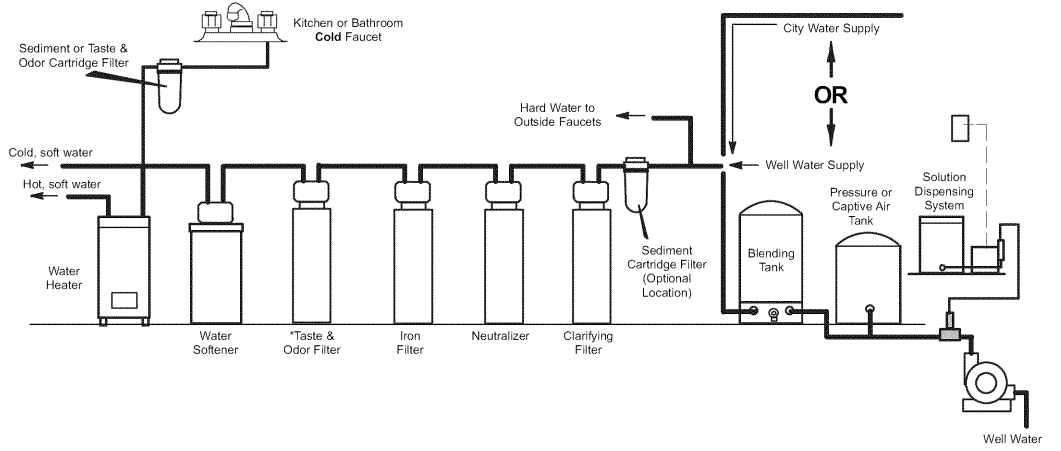
- Always place an Iron Filter UPSTREAM of the water softener.
- Always place a Neutralizer UPSTREAM of an Iron Filter, etc., as shown.
- Place a Taste & Odor Filter UPSTREAM of a water softener on a chlorinated water supply and DOWNSTREAM of a water softener on a non-chlorinated water supply.
WHERE TO INSTALL THE WATER SOFTENER
Review the following points before you choose a place to put your softener
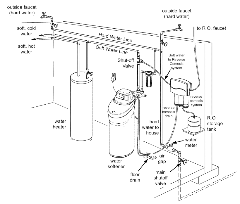
- Place as close as possible, but always after the pressure tank (well water) or water meter (city water). See Fig. 3.
- Place as close as possible to a water drain, such as a floor drain, laundry tub, sump, or standpipe. See Fig. 3.
- Connect to the house’s main water pipe BEFORE THE WATER HEATER. See Fig.3. The Temperature of water going through the softener must not be more than 120°F (49°C). Hot water will damage the inner softener parts. To reduce the risk of hot water backup, piping between the softener and water heater should be as long a run as possible.
- Keep outside faucets on hard water to save soft water and salt. See Fig. 3.
- Do not install in a place where the softener could freeze. Damage caused by freezing voids the warranty by Sears Brands Management Corporation.
- Put the softener in a place where water damage is least likely to occur if it develops a leak. Sears or the manufacturer will not repair or pay for water damage.
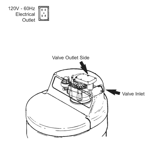
- A grounded, 120V electrical outlet is needed within 10 feet of the softener. See Fig. 3. This is to plug in the transformer. The softener has a 10-foot power cable. Be sure the outlet and transformer are in an indoor place to protect them from wet weather. Use a continuously “live” outlet, which cannot be accidentally switched off.
- When installing in an outside location, you must take the steps necessary to ensure the softener, installation plumbing, and wiring are protected from the elements, direct sunlight, contamination, vandalism, etc.
Suggested Slab Foundation Installation
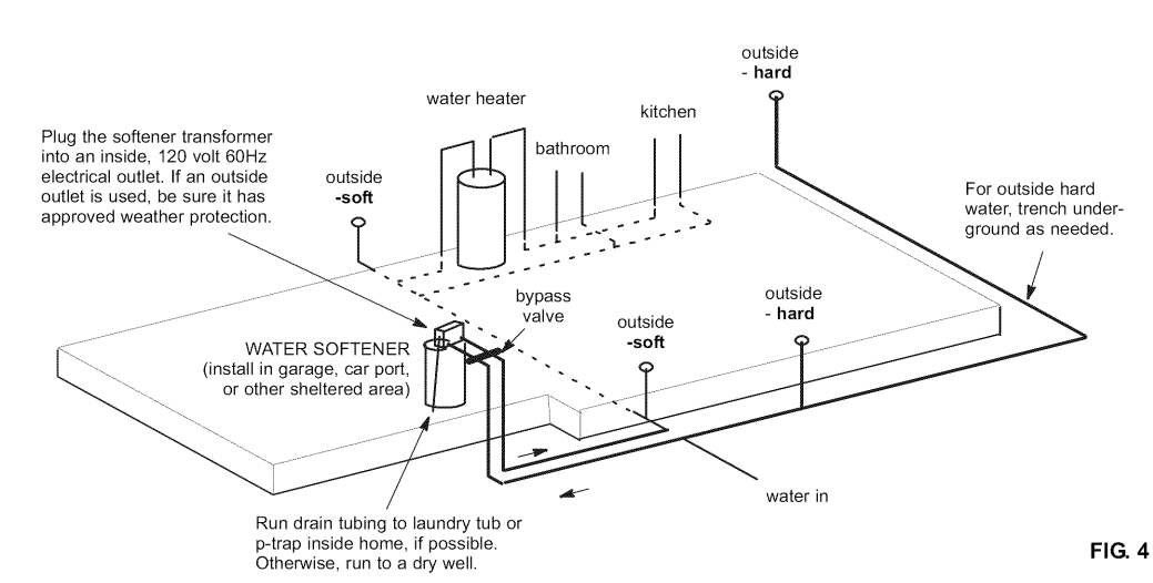
DRAW IN YOUR PIPES AND FITTINGS
Draw the plans for your “IN” and “OUT” piping here. Include all pipes, fittings, and
accessories you will use. Make a list of all materials you will need and buy them before you begin to install the water softener.

In what direction does the water flow?
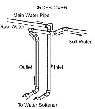
Be sure to plan “IN” and “OUT” piping so water flow is to the softener valve inlet. Plan a
crossover if the flow is from left to right.
PIPE, FITTINGS, OTHER MATERIALS NEEDED
- You must first decide how to run “in” and “out” pipes to the softener. Look at your house’s main water pipe at the point where you will connect the softener. Is the pipe soldered copper, glued plastic, or threaded galvanized or brass? What is the pipe size? What kind of pipe and fittings are easiest for you to work with, and what tools do you have? Now look at the common plans for “in” and “out” piping on soldered copper. See Fig. 6. Use it as a guide to plan what materials you will need.
- Get all the materials you will need before you start. Use Fig. 5 to make a plan drawing for your specific installation. “In” and “out” fittings included with the softener are 1″ NPT threaded adaptors. You should maintain the same, or larger, pipe size as the water supply pipe, up to the softener inlet and outlet. Use copper, brass, galvanized, or PVC plastic pipe and fittings for the “in” and “out” pipes. Be sure to check local codes.ALWAYS install the bypass valve (that is included with the unit) or a three-valve bypass. See Figs 9 to 13.
- Bypass valves let you turn off water to the softener if needed for repairs, but still have water in the house pipes. Drain tubing (3/8″ inside diameter) is needed for the valve and salt tank drains. See Fig. 16. If a rigid valve drain is needed to comply with plumbing codes, you can buy the parts needed (see Fig. 16) to change the softener to a 1/2 inch minimum copper tubing drain.
ASSEMBLE INLET OUTLET ADAPTORS, OR A SINGLE BYPASS VALVE
Complete the following steps to assemble the adaptors or bypass valve.
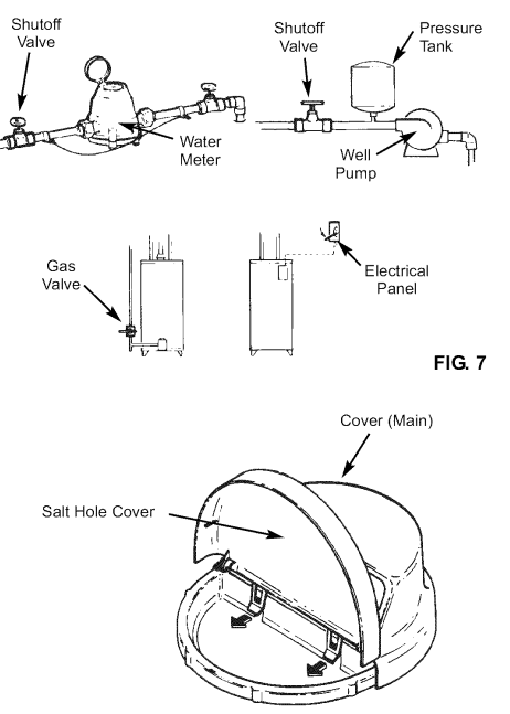
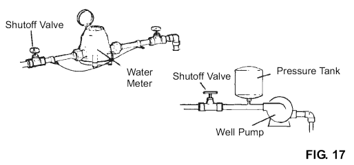
- Close the shutoff valve on the house main water pipe, near the water meter or pressure tank, to turn off the water. See Fig. 7.
- Shut off the gas or electric supply to the water heater. See Fig. 7.
- Open the highest and lowest water faucets in your house. This will let water drain from the pipes. Close faucets after water has drained.
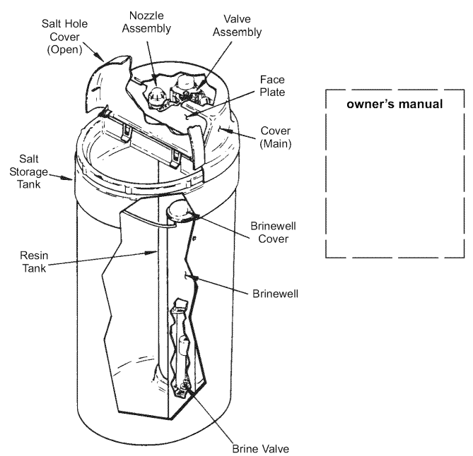
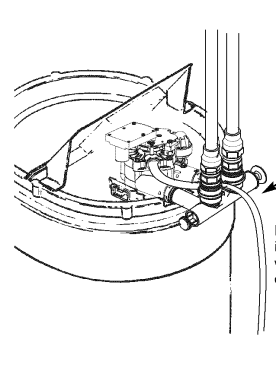
- Remove the main cover. Remove the salt hole cover first and then pull outward on the two tabs to release the main cover. See Fig. 8.
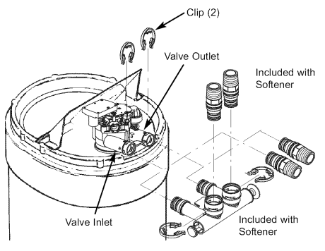
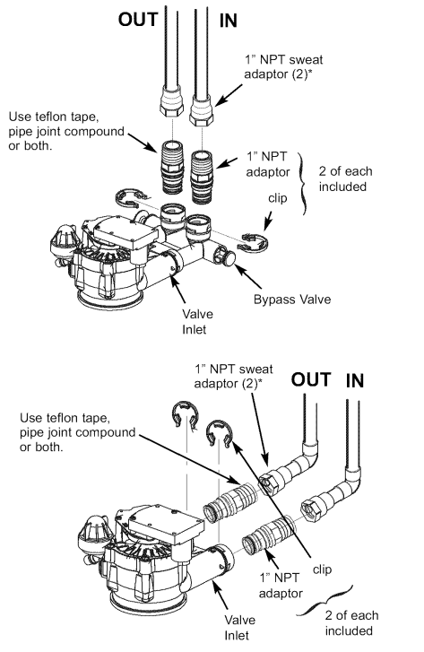
- Visually check and remove any foreign materials from the valve inlet and outlet ports. See Fig. 9. Carefully remove the two large plastic clips (you will use them).
Check to be sure the turbine and turbine support are firmly in place. See Fig. 10. - Put a light coating of silicone grease on the o-ring seals and slide them onto the bypass valve.

- Push the bypass valve into the softener valve as far as it will go. Snap the two large holding clips into place, from the top down as shown. See Fig. 11.
- Put a light coating of silicone grease on the o-ring seals and slide them into the threaded adaptors. Push the adaptors into the valve inlet and outlet ports, or bypass valve ports, as far as they will go. Both adaptors are the same and fit either port. Snap the two large holding clips into place, as shown. See Fig. 11.
POSITION SOFTENER INTO PLACE
Complete the following steps to position the softener.
- Grip under the ridge on the salt tank sidewall.
- Carefully rock back and forth into position.
- Move the softener into position.
- Place on a level and smooth surface. If needed, put a piece of 3/4″ plywood, at least 17″ x 20″, under the tank. Then put spacers under the plywood to level the softener. See Fig. 14.
CONNECT THE SOFTENER
Refer to your plan drawing. See Fig. 5. Measure, cut (thread if needed), and put all pipe and fittings together up to the main water pipe, or to the bypass valve(s) you installed in the previous step.
CONNECT THE VALVE DRAIN HOSE
- Take a length of 3/8″ inside diameter drain tubing and attach one end to the drain fitting. See Fig. 16. Use a tube clamp to hold it in place. Put the other end of the
tubing over a floor drain, into a laundry tub, standpipe, or other suitable drain. - Check your local codes. Leave an air gap of about 1-1/2″ between the end of the hose and the drain. This gap is needed so you don’t get a backflow of sewer water into the softener.
- Do not put the end of the hose into the drain or connect without the air gap. Place and support the hose so it does not kink or have sharp bends. Secure the hose end so water pressure does not cause the hose to “whip”. Tie or wire it in place. Do not pinch the hose shut. The softener will not work if this drain hose is pinched, plugged, closed, or restricted in any way.
- Direct drain flow down into the drain from the drain line, as the flow could over shoot the drain cover.
- Keep the hose lower than the drain fitting. In some homes, to get to a drain, you must raise the hose and run it overhead. If you need an overhead drain, do not raise the hose more than 8′ above the floor. A copper drain tube is best to use.
LEAK TEST
- Fully open two cold, soft water faucets near the softener.
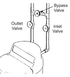
- Look at the pictures in Figs 18 and 19 to determine your kind of bypass valve(s). Place bypass valve(s) in “bypass” position. On a single valve, slide the stem inward to bypass. On a three (3) valve system, close the inlet and outlet valves and
open the bypass valve. - Fully open the house’s main water pipe shutoff valve. Observe steady water flow from both open faucets.
- Place bypass valve(s) in SERVICE EXACTLY as follows: Keep soft water faucets open.
- a. Single Bypass Valve: Slowly, slide the valve stem outward toward service, pausing several times to allow the softener to pressurize slowly.
- b. Three Valve Bypass: Fully close the bypass valve and open the outlet valve. Slowly, open the inlet valve, pausing several times to allow the softener to pressurize.
- After about three minutes, open a hot water faucet for about one minute, or until all air is expelled, then close.
- Close both cold water faucets.
- Check your plumbing work for leaks and fix them right away if any are found. Be sure to observe previous caution notes.
HOUSE MAIN WATER SHUTOFF VALVES
SINGLE BYPASS
VALVE BYPASS
PROGRAM THE TIMER
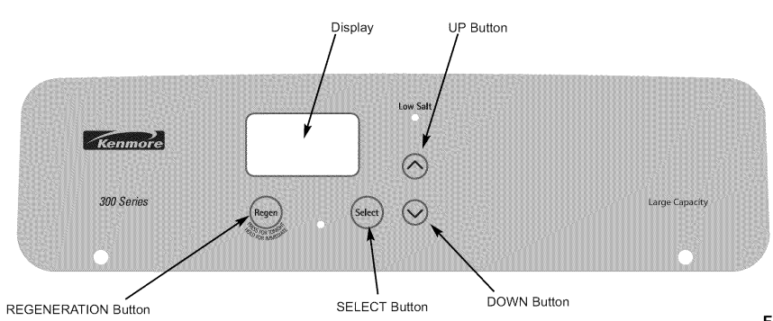
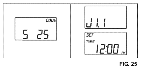
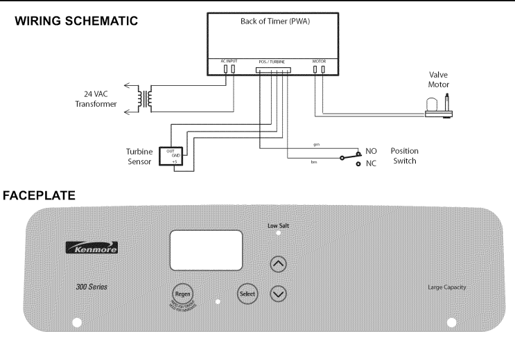
- When the transformer is plugged in, a model code (S 25) and a test number (example: J1.1) are shown on the face plate. This will display for four (4) seconds. Then, at 12:00 PM and the words SET TIME begin to flash. NOTE: If it shows in the display, press the UP or DOWN button until S 25 shows in the display. Then, press the SELECT button to set, and change to the flashing SET TIME display.

- To check the model code, unplug the transformer from the wall outlet and plug in again. If other than S 25 shows, refer to the Troubleshooting Section. SOUND “BEEPER”: A “beeper” sounds while pressing buttons for timer setup. One beep signals a change in the face plate display. Repeated beeps mean the timer will not accept a change from the button you have pressed, telling you to use another button. For example, while setting the hardness, the beeper sounds repeatedly when the display reaches 1 using the DOWN button, or the highest hardness setting using the UP button.
SANITIZE THE WATER SOFTENER
Care is taken at the factory to keep your water softener clean and sanitary. Materials used to make the softener will not infect or contaminate your water supply or cause bacteria to form or grow. However, during shipping, storage, installation, and operation, bacteria could get into the softener.
CARE
SALT BRIDGE
Sometimes, a hard crust or salt bridge forms in the salt storage tank. It is usually caused by high humidity or the wrong kind of salt. When the salt bridges, a space forms between the water and salt. Then salt will not dissolve (melt) in the water to make brine. Without brine, the resin bed does not regenerate, and you will have hard water.
KEEPING THE WATER SOFTENER CLEAN
NOZZLE & VENTURI
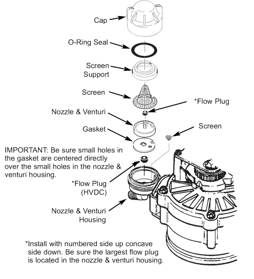
A clean nozzle and venturi (see Fig. 42) is a must for the softener to work right. This small unit moves brine from the salt storage tank to the resin tank during regeneration. If it becomes plugged with sand, silt, dirt, etc., the softener will not work, and you will get hard water. To clean the nozzle and venturi, complete the following steps:
- Remove the softener top cover. Be sure the softener is in service cycle (no water pressure at the nozzle and venturi).
- Turn off the cap from the nozzle and venturi housing.
- Lift out the screen support and screen. Do not lose the large o-ring seal.
- Remove the nozzle and venturi. Wash and rinse the parts in warm water until clean. If needed, use a small brush to remove iron or dirt. Also, check and clean the gasket, flow plug, and screens.
- Carefully replace all parts in the correct order.
- Lubricate the o-ring seal with silicone grease or Vaseline and place it in position.
- Install and tighten the cap by hand only. Do not overtighten, which may break the cap or housing.
CHECKLIST TO HELP YOU SAVE MONEY
If your water softener fails to work, make the following easy checks. Often, you will find what is wrong yourself, and you won’t have to call and wait for service. If you do not find anything wrong while making the checks, and your softener still does not work, call your Sears Service Department.
- Also read ERROR CODE.
- If an error code is not displayed, press and hold the SELECT button until the display changes. Then, press the SELECT button again and hold until a flashing model code appears. For Model No. 625.383060, it must show S 25. If any other number shows, the face plate computer is working on incorrect input and would probably be the cause of the problem. To set the correct code, press either the UP or DOWN button. When the correct model code (S 25) shows, press SELECT to return a flashing 12:00 AM display. Reset the present time, hardness number, etc.
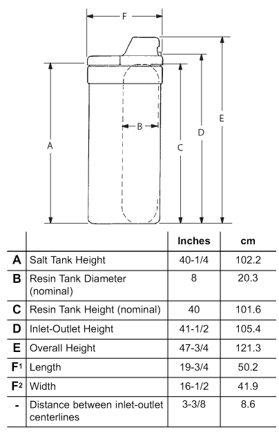
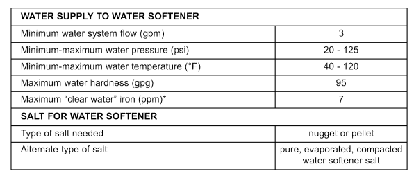
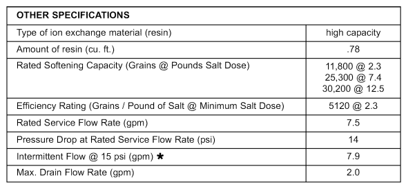
SPECIFICATIONS
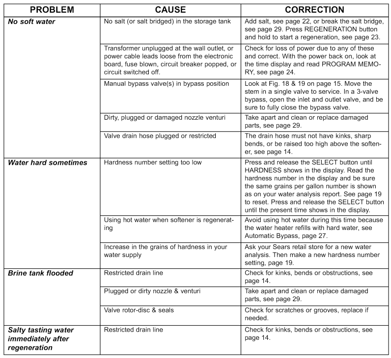
MODEL NO. 625.383060 – TIMER CODES
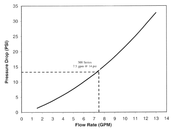
Pressure Drop (PSI) vs. Flow Rate (GPM)
SERVICE
ALWAYS MAKE THESE INITIAL CHECKS FIRST
- Does the time display show the correct time of day?
- If the display is blank, check the power source to the softener.
- If time is flashing, the power was off for over 6 hours. The softener resumes normal operation, but regenerations occur at the wrong time.
- If an error code (Example: Err3) shows in the faceplate display, go to AUTOMATIC ELECTRONIC DIAGNOSTICS.
- Plumbing bypass valve(s) must be fully in the service position.
- The inlet and outlet pipes must connect to the softener inlet and outlet respectively.
- Is the transformer plugged into a “live”, grounded wall outlet, and the power cable fastened securely to the controller? FIG. 46
- The valve drain hose must be free of kinks and sharp bends, and not elevated over 8 ft. above the floor.
- Is there salt in the storage tank? Is the brine tubing connected? Brine tubing connects to the nozzle, venturi, and the brine valve assembly.
- Is the brine valve float set right?
- Press the SELECT button two times to display the hardness setting. Be sure it is the correct setting for the household’s water supply. (Make a hardness test of the raw water and compare it with the hardness setting. Also, test a soft water sample to verify if a problem exists.) Press the SELECT button twice more to return to the present time in the display.
- If you do not find the problem after making the initial checks, do the MANUAL INITIATED ELECTRONIC DIAGNOSTICS and the MANUAL ADVANCE REGENERATION CHECK.
FOR MORE MANUALS BY Kenmore, VISIT MANUALSLIBRARYY
Kenmore 300 Series Water Softener-FAQs
How do I know if my Kenmore water softener is working?
You can test your water using hardness test strips. Hard water should show before the softener, while softened water after the unit should show reduced hardness.
How does a Kenmore water softener work?
Water enters through the inlet port, passes through the resin media where hardness minerals are removed, and then flows out through the outlet port as softened water.
How much water should be in the bottom of the tank?
It is normal to see 0–4 inches of water at the bottom. Anything higher could indicate a system issue.
Why is my water softener not regenerating?
Common reasons include a stuck control valve, motor failure, or worn seals. Try pressing the regeneration button—if the cycle starts, the motor is functioning.
Why is the low salt light blinking?
This means the salt level is low. Refill the tank so the salt level is between the 2–5 mark on the brine well.
How do I adjust the settings on my Kenmore softener?
You can set the current time, water hardness, and recharge time using the control panel. Adjust settings according to your water test results.
How long does it take for softened water to show results?
Softened water is available almost immediately for cold taps, but it may take up to 48 hours for hot water because the tank needs to cycle out the hard water first.
What is the lifespan of a Kenmore water softener?
With proper care, Kenmore water softeners typically last around 8–10 years.

