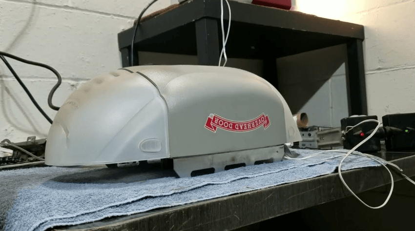
Overhead Door Model 1026
PRE-INSTALLATION CHECK LIST
Things to consider if you are planning to “Do-it-yourself.”
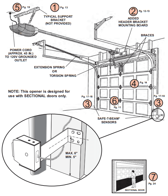
This opener is designed for use with SECTIONAL doors only. In many cases, you will be replacing an existing door opener with a new one, however, if this will be the first opener installed, some pre-installation issues need to be addressed. They are as follows:
The Overhead Door Corporation recommends that you read and fully understand all information and instructions contained herein before choosing a “Do-it-yourself” installation. Any questions should be directed to Overhead Door Corporation or an authorized Overhead Door Dealer.
(The issue numbers below refer to the circled numbers in the illustrations on page 5.)
- Check your ceiling where the power head of your new unit will be mounted. Plan how you will be mounting the power head. It is possible that the ceiling joists may not be in the position needed for the garage door opener. It may be necessary to add brackets and fasteners (not included with your new door opener kit). (Refer to Section 2.)
- Check the wall directly above the garage < door. The door opener’s header bracket must be securely fastened to this wall. Ensure that the structure will provide a strong mounting location. (Refer to Section 2.)
- Check to see if the mounting location for the Safe-T-Beam® is clear from Check to see if the mounting locatior obstructions and has a wood surface available for attaching the mounting brackets. The brackets may be attached to concrete if necessary, but extra tools and special fasteners (not supplied) will be required. (Refer to Sections 4 and 5.)
NOTE: Mounting brackets must be installed within code specifications. - Is your sectional garage door made of aluminum, light-weight steel, fiberglass, or glass panels? Additional support bracing must be added to these types s doors. If this is the case, please contact the door manufacturer or authorized dealer so that they can furnish you with a “bracing kit.” (Refer to Section 2.) WARNING! To reduce the risk of injury to persons or property damage, use this opener only with sectional doors.
- You need a properly grounded 110-120-volt power supply available. The outlet should be You need a properly grounded 110-120 Volt no more than 3 feet from the power head once it is mounted. (Refer to Section 5.) WARNING: DO NOT USE AN EXTENSION CORD! DO NOT USE A PORTABLE GENERATOR! This product is designed to operate on standard household current. DO NOT USE ALTERNATE POWER SUPPLIES.
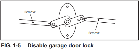
- To avoid damage to your door and/or opener, make sure you disable and/or To avoid damage to your door and/or remove any door locks, ropes, and/or cables (NOT door lift cables) before installing your opener. (Refer to Section 1.)

- Ensure that your door is properly balanced and moving freely. (Refer to Section 2.) WARNING: If your door jams, binds, is improperly balanced, or has a broken spring, have it repaired or adjusted by a trained door system technician. Door springs, cables, pulleys, brackets, and associated hardware are under extreme tension and can cause serious injury or death. (NOT SHOWN) If your garage does not have
- (NOT SHOWN) If your garage does not have a separate entry door, you should consider an emergency release kit (GER-2) for installation on your garage door. (See emergency release kit notes on page 20.)
TYPICAL SECTIONAL DOOR INSTALLATION
WARNING
To reduce the risk of injury to persons or property damage, use this opener only with sectional doors.
RECOMMENDED TOOLS

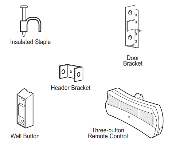
PARTS IDENTIFICATION
– Not Shown Full Size.

IMPORTANT INSTALLATION INSTRUCTIONS
WARNING: To reduce the risk of severe injury or death
- READ AND FOLLOW ALL SAFETY, INSTALLATION, AND OPERATION INSTRUCTIONS. (If you have questions or do not understand an instruction, call the Overhead Door Corporation or an authorized Overhead Door Dealer.)
- Install only on a properly balanced sectional garage door. An improperly balanced door could cause severe injury. Have a trained door system technician make repairs or adjustments to cables, spring assemblies, and other hardware before installing the opener.
- Remove all ropes and remove or make inoperative all locks connected to the garage door before installing the opener.
- Where possible, install the door opener 7 feet or more above the floor. For products having an emergency release, mount the emergency release 6 feet above the floor.
- Do NOT connect the opener to the source of power until instructed to do so.
- Locate the control button:
- Within sight of the door,
- At a minimum height of 5 feet, so small children are not able to reach it, and
- Away from all moving parts of the door.
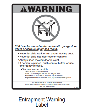
- Install the Entrapment WARNING Label next to the control button in a prominent location. Install the Emergency Release Tag on or next to the emergency release.
- After installing the opener, the door must reverse within 2 seconds when it contacts a 1-1/2 inch high object (or a 2 x 4 board laid flat) on the floor.
NOTE: Please follow ALL instructions in their NUMBERED sequence. Use the Wall Button and safety sensors provided with this unit. Do NOT substitute Wall Button or safety sensors.
OPENER ASSEMBLY
RAIL ASSEMBLY: Use a clean, flat surface.
WARNING: To reduce the risk of injury to persons or property damage, use this opener only with sectional doors.
CAUTION: Do NOT run until the opener is fully assembled.
Clear a workspace area to unpack and organize the box and contents for assembly.
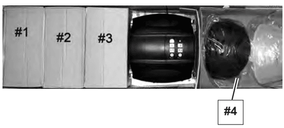
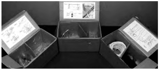
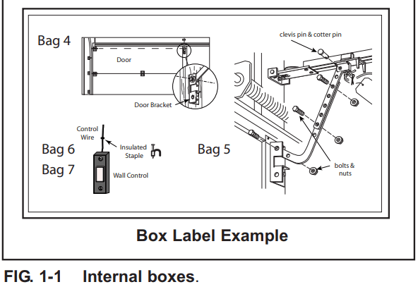
- There are 4 or more boxes inside the carton. Each box is numbered 1 – 4. Note that some openers will contain the same parts and be packaged with fewer boxes. Carefully remove the three internal boxes (Labeled #1, 2, and 3) and place them on the floor for easy access (Fig. 1-1). These boxes contain assembly parts, and the contents are organized by assembly tasks. For quick reference, inside the lid of each box, there is a label illustrating the components inside.


- Remove the motor power head and place it on the floor for later use. Remove box #4 and place it on the floor for later use.
POWER HEAD & RAIL ASSEMBLY
Assembly for CHAIN DRIVE OPENER
NOTE: Handle carefully! The drive chain can slide out of the rail.
NOTE: For the power head and rail assembly, locate Bag 1 from Box 1.
NOTE: Copy the serial number from the power head frame and record it on the warranty page.
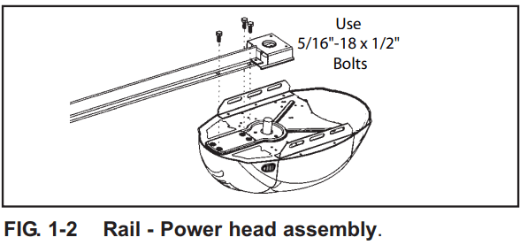
- Attach the rail assembly to the power head by aligning the sprocket onto the motor shaft. Use (3) bolts, 5/16″-18 x 1/2″ (Fig. 1-2).

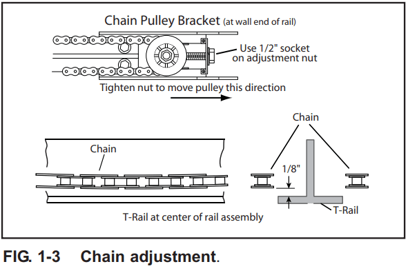
- Tighten the chain by turning the adjustment nut clockwise. The chain adjustment nut is located in the Chain Pulley Bracket (opposite rail end from the power head) (Fig. 1-3).

- Tighten chain until chain is approximately 1/8 inch above the base of the rail at midpoint on the rail (Fig. 1-3). Do NOT over tighten chain.
CAUTION: You should have removed all ropes and/or cables (NOT door lift cables) and disabled the door lock already. If you have not, remove all ropes and/or cables and disable garage door lock NOW before continuing with installation (Fig. 1-3).
Set the assembled power head and rail aside. Begin with Section 2, INSTALLATION.
Assembly for BELT DRIVE OPENER
NOTE: For the power head and rail assembly, locate Bag 1 from Box 1.
NOTE: Copy the serial number from the power head frame and record it on the warranty page.
- Attach the rail assembly to the power head by aligning the sprocket onto the motor shaft. Use (3) bolts, 5/16″-18 x 1/2″ (Fig. 1-4).

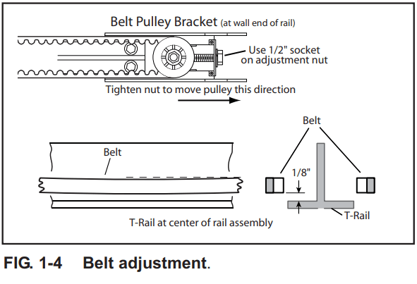
- Tighten the belt by turning the adjustment nut clockwise. The belt adjustment nut is located in the Belt Pulley Bracket (opposite rail end from the power head) (Fig. 1-the 5).

- Tighten the belt until the belt is approximately 1/8 inch above the base othe f the rail at the midpoint on the rail (Fig. 1-5over-tightener tighten belt.
CAUTION: You should have removed all ropes and/or cables (NOT door lift cables) and disabled the door lock already. If you have not, remove all ropes and/or cables and disable the garage door lock NOW before continuing with installation (Fig. 1-3)the .
Set the assembled power head and rail aside. Begin with Section 2, INSTALLATION.
INSTALLATION
HEADER AND DOOR MOUNTING BRACKETS
WARNING
The header bracket must be fastened to the garage framing. Do NOT fasten to drywall, particleboard, plaster, or other similar materials.
- Finding the header bracket mounting location.
- Close the garage door.
- Use a pencil and a level.
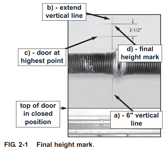
- Mark center of garage door (one-half overall width) on the wall with 6″ vertical line at top edge of door.
- Continue the s line on all the above doors for about 12″ (Fig. 2-the 1, a).

- Use a pencil and a level.
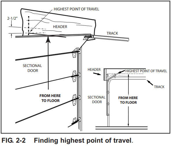
- Raise the garage door until the top edge of the door reaches its maximum height (Fig. 2-2).the the
- With the or at the highest point.
- Measure the ight from the edge of he floor to the floor (Fig. 2-2).

- Measure the ight from the edge of he floor to the floor (Fig. 2-2).
- Close the door again.
- Mark height measurement on wall above door (Fig. 2-1, c).
- Make your mark across the vertical line made earlier.
- Add 2-1/2″ to height mark just made on wall. This is location for header bracket (Fig. 2-1, d).
WARNING:
Door springs are under high tension. If spring or its shaft is in the way, measure 2-1/2″ above spring or shaft on the garage door centerline and mark this height as your location for the header bracket. Do NOT move the door spring!
NOTE:
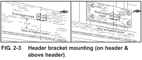
If the header bracket location needs to be above the header for the garage door opening, you need to add a “mounting surface.” A 2″ x 6″ board securely attached (board and fasteners not included) to wall studs on either side of your mark is sufficient (Fig. 2-3).
NOTE: Fothe r header bracket and bolts, locate Bag 2 from Box 1.
NOTE: The bolts supplied in Bag 2 are designed pressure pressure-treated lumber.
- Close the garage door.
- Mounting the header to the bracket.
- Hold the header bracket against all (Fig. 2-3).
- Position bracket as shown.
- Place the ace center on the vertical line.
- Bottom edge on final height line.
- Mark screw hole locations on wall.
- Drill 3/16″ pilot holes at each screw hole mark.
- Fasten header bracket with 2 lag screws (provided) (Fig. 2-3).
MOUNTING THE OPENER
- Getting started.
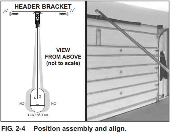
- Position the d rail on the wall next to the header bracket (Fig. 2-4).

- Place the ace material on the floor under power head to protect from scratching. (A box, stool, or similar device may be needed to clear a torsion spring.)
NOTE: For the header bracket, the t pins are located in Bag 2 from Box 1.
- Place the ace material on the floor under power head to protect from scratching. (A box, stool, or similar device may be needed to clear a torsion spring.)
- Position the d rail on the wall next to the header bracket (Fig. 2-4).
- Mounting the assembly.
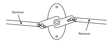
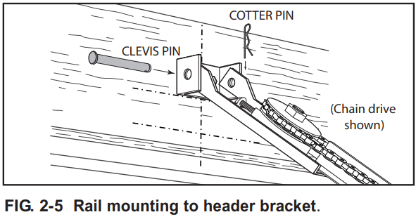
- Attach rail to header bracket using clevis pin and cotter pin (Fig. 2-5).

- Support a step ladder to prevent interference with the header-mounted (torsion) spring.
NOTE: Before final attathe chment toensureng, ensure that the assembly is in proper alignment (Fig. 2-4).
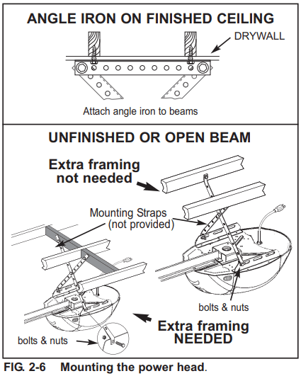
NOTE: For nuts, bolts, and lag screws locate Bag 3 from Box 1. - On finished ceilings, locate ceiling joists or trusses using a stud finder or similar device. Attach angle iron (not provided) to joists or trusses through finish material using (provided) lag screws (Fig. 2-6).

- On unfinished ceilings or open ceilings, straps may attach directly to joists or trusses. Depending on the garage construction, extra framing material (not provided), which may be required, should be installed using appropriate construction techniques (Fig. 2-6).
NOTE: Refer to your local building codes for appropriate framing materials and construction techniques. - Attach mounting straps (not provided) to the ceiling using lag bolts (Fig. 2-6).
- Set the height of the power head to the following (Fig. 2-6): a) The Rail must clear the door at the door’s highest point of travel. b) Be level or power head slightly below level.
- Securely tighten power head mounting bolts and nuts.
- Carefully raise and lower the door manually. Ensure the door does not contact any section of the power head or rail.
- Check that rail clamp bolts and nuts are tight.
- DO NOT PLUG THE OPENER IN YET!
- Attach rail to header bracket using clevis pin and cotter pin (Fig. 2-5).
DOOR BRACKET
CAUTION: Doors made of masonite, lightweight wood, fiberglass, and sheet metal must be properly braced before mounting door opener. Contact door manufacturer or distributor for a bracing kit. The Overhead Door Corporation is not responsible for damage caused due to improperly braced door.
NOTE: For the door bracket and bolts, locate Bag 4 from Box 2.
- Finding the door bracket mounting location.
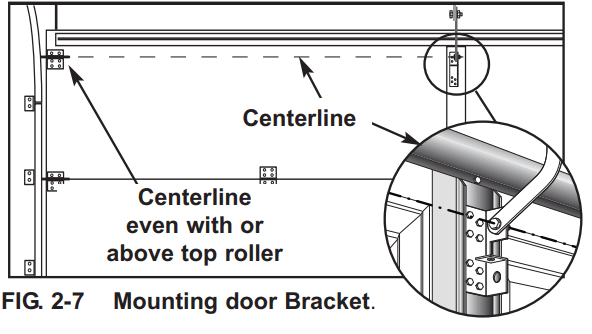
- The door bracket is mounted as high on the door as possible along the vertical centerline and NO LOWER THAN the top set of rollers (Fig. 2-7).

- The door bracket is mounted as high on the door as possible along the vertical centerline and NO LOWER THAN the top set of rollers (Fig. 2-7).
- Mounting the door bracket.
- Proper bracing should be verified at this point.
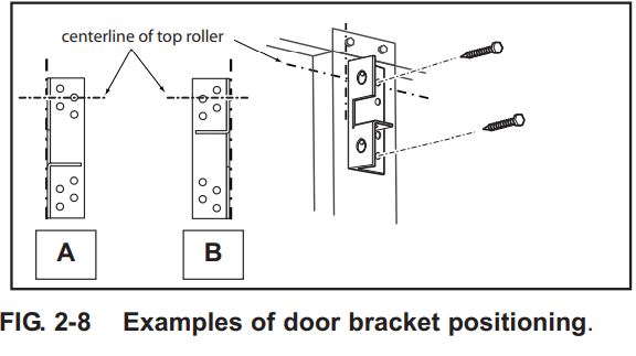
- Align the door bracket centered on your vertical centerline (Fig. 2-8).

- Attach using 3 self-drilling screws for sheet metal or other light weight material.
- Use lag screws (not provided) for solid wooden sectional doors.
- Align the door bracket centered on your vertical centerline (Fig. 2-8).
- Proper bracing should be verified at this point.
NOTE: For solid wood doors, carriage bolts WITHOUT SLOTTED HEADS (not included) may also be used for attaching door bracket.
INSTALL DOOR ARMS
NOTE: For door arm nuts and bolts, clevis and cotter pins, locate Bag 5 from Box 2.
- Attach the arms.
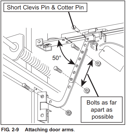
- Fasten the short branch of the curved door arm to the door bracket using a bolt and locking nut (Fig. 2-9).

- Fasten the right arm to the carriage using a short clevis pin and cotter pin (Fig. 2-9).
- Fasten the short branch of the curved door arm to the door bracket using a bolt and locking nut (Fig. 2-9).
- Connecting the arms.
- Slide the carriage back and forth to adjust arm length.
- Position the straight arm 50° down from the rail.
- With the arms arranged in this position, fasten arms together using bolts and nuts spaced as far apart as possible (Fig. 2-9).
- Slide the carriage back and forth to adjust arm length.
WALL BUTTON INSTALLATION
WARNING:
Verify there is NO power to the opener before installing the Wall Button wires and the Wall Button.
CAUTION: Staples that are too tight can cut or pinch wires. Cut or pinched wires can cause the Wall Button to stop working. When using the insulated staples, make sure you fasten them only as tightly as needed to hold the wire snugly.
WARNING: Use of any other wall control can cause the door to operate unexpectedly and the light not to work. Use only the included Wall Button.
NOTE: For Wall Button, wire and insulated staples, locate Bags 6 and 7 from Box 2.
- Wall Button location.
- Wall Button location should be in direct sight of the door.
- It should be at least five feet (5) above the floor to prevent small children from operating the door..
- It must be away from any moving parts. You should NOT be able to reach the garage door while standing athe t the Wall Button.)
- Wall Button board screw connections are polarized, (+) positive and (-) negative.
- Wiring (if pre-wired).
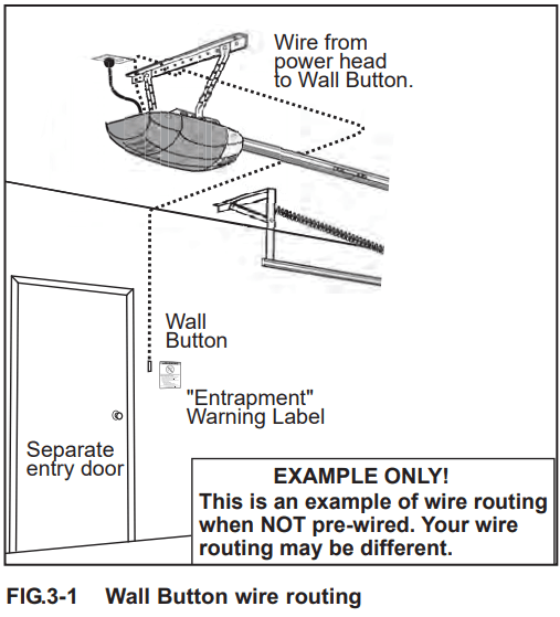
- Locate Wall Button pre-wired wire ends (Fig. 3-1). (They should be located within the guidelines mentioned above.)
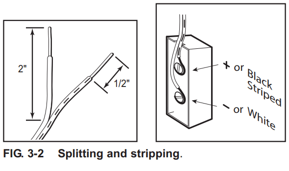
- Split and strip ends of wire (Fig. 3-2).

- Fasten wire to Wall Button board screws on back of Wall Button.
- Strip the wire to the + (plus) terminal.
- White wire to the – (minus) terminal.
- Wiring (If NOT pre-wired).
- Pick a convenient location for mounting the Wall Button using the guidelines mentioned above (Fig. 3-1).
- Run wire from the Wall Button to the power head (Fig. 3-1).
- Split and strip ends of wire (Fig. 3-2).
- Fasten wire to control board screws on back of Wall Button button.
- Strip wire to the + (plus) terminal.
- White wire to the – (minus) terminal.
- Securely fasten wires.
- Securely fasten wires to the ceiling and wall using insulated staples provided.
- Use insulated staples.
- Staples should be snug only.
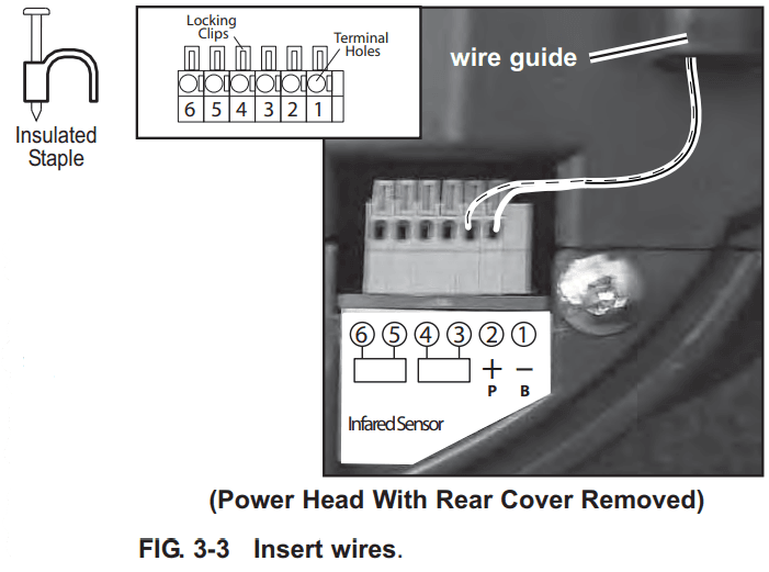
- If the rear cover is attached to the power head, remove it.
- On the power head:
- Route the Wall Button wires through the wire guide.
- Split and strip ends of wire (Fig. 3-2 on previous page).
- Insert the wire into the terminal holes and lightly press in the orange locking clips above each terminal hole. (You can use a pencil or small screwdriver to comfortably press in locking clips.) The white wire into the #1 terminal hole and the striped wire into the #2 terminal hole.
- Confirm the wire lock by lightly tugging on the wire. The wire should remain in the terminal hole.
- Do NOT install the rear cover yet.

- Securely fasten wires to the ceiling and wall using insulated staples provided.
- Mounting.
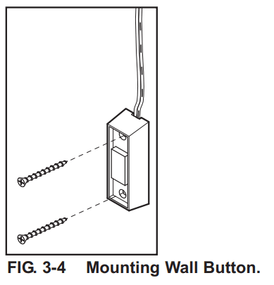
- Fasten Wall Button to wall with 2 screws rovided) (Fig. 3-4)

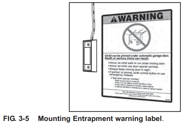
- Remove protective backing from “Entrapment” warning label (Fig. 3-5). The “Entrapment” label is located in the center of this manual.
- Stick the label on the wall near the Wall Button.

- Stick the label on the wall near the Wall Button.
- Fasten Wall Button to wall with 2 screws rovided) (Fig. 3-4)
SAFE-T-BEAMP SYSTEM INSTALLATION
WARNING: There should be no electrical power to the opener while installing Safe-T-Beam® wires. If you have plugged in the power cord-UNPLUG IT NOW!
NOTE: The opener will not close the door automatically unless the Safe-T-Beam® System is installed.
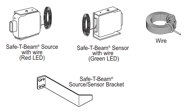
NOTE: For Sensors, screws, wire, and insulated staples locate items and Bag 8 from Box 3.
- Mounting brackets.
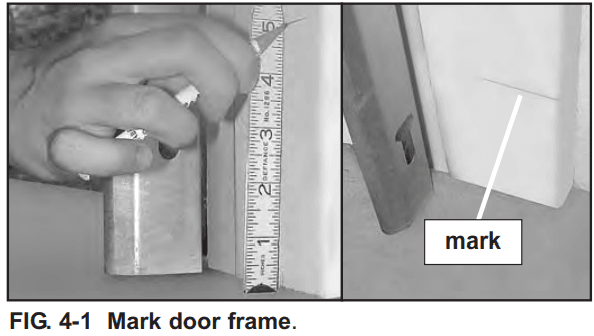
- Mark both sides of the garage door frame or wall at a height no higher than 6″ and no lower than 5″ above the floor (Fig. 4-1).

- Hold the bracket against a door frame or wall.
- Check if brackets extend out from wall far enough, so tongue of bracket is beyond door, tracks and any door hardware.
- If not:
- a) Mounting bracket extensions are available through an authorized Overhead Door dealer.
- b) Blocks of wood, etc., may be substituted for extensions.
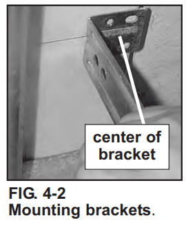
- Locate the top of the bracket on your mark (Fig. 4-2).

- Fasten each with 2 screws (Fig. 4-2).
NOTE: Mounting brackets can be attached to the floor or concrete rim using concrete anchors (not provided), and obey the manufacturer’s instructions.
- Mark both sides of the garage door frame or wall at a height no higher than 6″ and no lower than 5″ above the floor (Fig. 4-1).
- Mounting Safe-T-Beam® Source (Red LED) and Sensor (Green LED).
- If the garage has only one garage door.
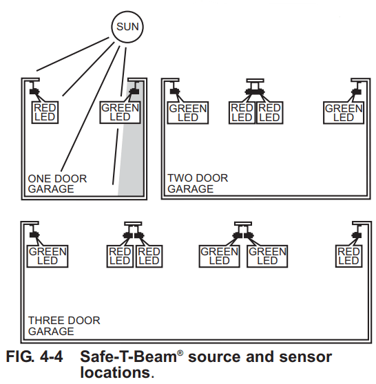
- Determine which side of the garage receives the most direct sunlight (Fig. 4-4).

- Red LED should always be on the sunny side whenever possible (Fig. 4-4).
- Determine which side of the garage receives the most direct sunlight (Fig. 4-4).
- For multiple doors.
- Preventing crossed signals is critical.
- Place source and sensor modules on adjacent doors facing in opposite directions (Fig. 4-4).
NOTE: To help prevent interference from the sun, the Safe-T-Beam® sensor with Green LED may be placed further away from the door opening, though extended no further out from the wall, where it will spend more time in shadow.
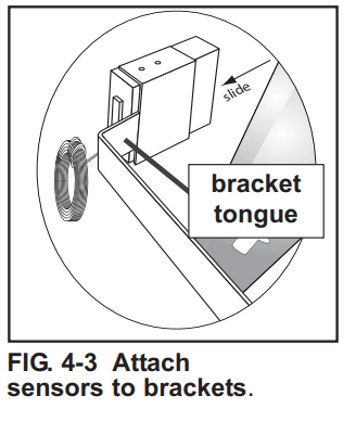
- Slide the source/sensor onto tongue of bracket until it clicks into place (Fig. 4-3).

- If the garage has only one garage door.
- Wiring (If NOT pre-wired).
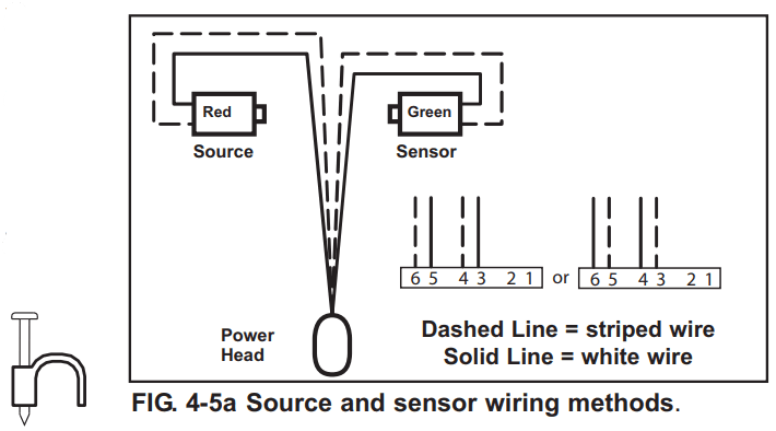
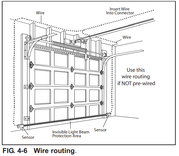
- Route wire from Safe-T-Beam® sensors to power head using method shown in (Fig. 4-5a).

- Securely fasten wires to the wall and ceiling as you go (Fig. 4-6 on next page).
- Use insulated staples.
- Staples should be snug only.
- Route wire from Safe-T-Beam® sensors to power head using method shown in (Fig. 4-5a).
- Wiring (pre-wired).
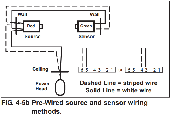
- Route wire from wall to Safe-T-Beam® sensors (Fig. 4-5b).

- Splice pre-wiring to shortened sensor wire, match wire pairs, dash-to-dash, and plain-to-plain.

- Trim the sensor wire to approximately one foot (1 ft) from the sensor.
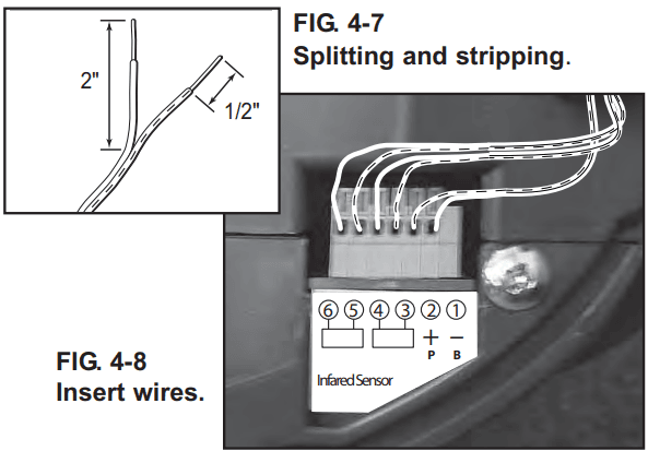
- Split and strip ends of sensor wires and pre-wired wires (Fig. 4-7).

- Splice wires together with (provided) wire nuts.
- Route wire from the ceiling to power the head (Fig. 4-5b).
- Securely fasten wires where they exit the wall and ceiling as you go.
- Use insulated staples.
- Staples should be snug only.
- Route wire from wall to Safe-T-Beam® sensors (Fig. 4-5b).
- Split and strip ends of sensor wires (Fig. 4-7).
NOTE: For rearcover, relocate Box 4. - Attach Safe-T-Beam® to the power head wire terminal.
- Route Safe-T-Beam® wires through the wire guide.
- Insert the wire into terminal holes and lightly press in the orange locking clips above each terminal hole. (You can use a pencil or small screwdriver to comfortably reach in and lightly press down locking clips.) Insert white wires into ‘even’ numbered terminal holes and striped wires into ‘odd’ terminal holes (Fig. 4-8).
- Confirm the wire lock by lightly tugging on the wire. The wire should remain in the terminal hole.
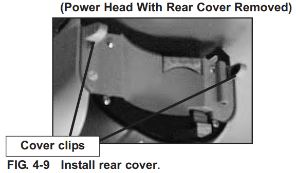
- Install rear cover. The rear cover is the same color as the power head clips and body (Fig. 4-9).

- Do not install the white (lamp) cover at this time.
NOTE: Safe-T-Beam® alignment check must be performed following connection to electrical power (see page 18). DO NOT PLUG IN YET!
- Route Safe-T-Beam® wires through the wire guide.
MAINTENANCE
ROUTINE MONTHLY MAINTENANCE
- Door balance.
- With the door closed, pull emergency release knob (Carriage Lock) towards the opener to release door from carriage assembly.
- Raise the door manually approximately 3′- 4′ and release.
- The door should remain stationary or move very slightly.
- If the door moves quickly, CONTACT A TRAINED DOOR SYSTEM TECHNICIAN.
- Close the door.
- Pull emergency release knob towards door to engage carriage.
- Operate the door using the remote.
- The door will reattach itself to the carriage assembly.
- Contact reverse.
- Place a 2″ x 4″ board laid flat on the floor.
- In the center of the garage door opening.
- Close the door by using the wall button or the remote control.
- Door fails to reverse on contact with board (See section 6 “CONTACT REVERSE.”)
- Opener still fails. CONTACT OVERHEAD DOOR CORPORATION OR AN AUTHORIZED OVERHEAD DOOR DEALER.
- Place a 2″ x 4″ board laid flat on the floor.
- Safe-T-Beam® System.
- Red LED blinks.
- Check alignment (See section 5).
- Red LED blinks.
TROUBLESHOOTING GUIDE
Opener does NOT run from the Wall Button.
WHAT TO DO
- Check the power source.
- Plug a lamp into the outlet used for the power head. If the lamp works, the power source is OK.
- If not, check the fuse or circuit breaker.
- If power is OK.
- Check connections at the power head terminals and the Wall Button.
- Check for reversed, broken, or cut wires. Staples can cut insulation and short wires. Repair or replace.
Opener runs, but the door does NOT move.
WHAT TO DO
- Make sure the carriage is engaged to the carriage slide.
- Place the carriage lever in the lock position.
- Check to make sure the chain is not broken or OFF its track.
- Check FORCE ADJUSTMENT (See section 6). Door opener will NOT run more than 30 seconds each way if door does not move.
Opener works from the Wall Button, but NOT from the remote control.
WHAT TO DO
- Program the remote control code into the receiver memory. (See section 7).
- Replace the remote control battery. (See section 8 ).
The remote control has less than 25 feet of operating range or no operation.
WHAT TO DO
- Relocate the remote control inside the car and or point the remote control at the garage door.
- Replace battery (See section 8).
- Reposition the door opener antenna.
- Red LED blinks while button is being pushed, or LED does not come on – battery is low, replthe ace battery.
The door starts down, then STOPS and goes back up.
OR
Safe-T-Beam® System malfunction.
WHAT TO DO
- If a NEW installation, check Door Arm position (See section 2).
- Check if the Safe-T-Beam® Red LED is flashing.
- Check the Safe-T-Beam® system for beam obstruction or misalignment of lenses. Realign or replace Sensors. (See section 3).
- Check “CLOSE FORCE” adjustment (See section 6).
- Check the garage door for binding.
- If an operational problem exists, and opener will not run closed. The opener can be forced to close as follows (See section 5). Hold the Wall Button down until door is completely closed.
- Disconnect the Safe-T-Beam® System from the opener and contact an authorized Overhead Door Dealer or contact Overhead Door Corporation at 1.800.929.3667.
Door starts up, but STOPS before it’s completely open.
WHAT TO DO
- Be sure the door, opener, and springs are in good repair, properly lubricated, and balanced (See Maintenance section 10).
- Check “OPEN” limit setting (See section 6).
- Check “OPEN FORCE” adjustment (See section 6).
- WARNING: If you suspect a problem with the garage door hardware or springs, contact an authorized Overhead Door Dealer or a trained door system technician, or contact Overhead Door Corporation at 1.800.929.3667.
The door will only open.
WHAT TO DO
- Check CONTACT REVERSE (See section 6).
- Check the garage door for binding.
- Wires shorted. Staples can cut insulation and short wires. Repair or replace.
- Check “CLOSE FORCE” adjustment (See section 6 ).
Noisy operation.
WHAT TO DO
- Be sure all fasteners are tight.
- Be sure door and opener is in good repair, properly lubricated and balanced (See Maintenance section 10).
For more manuals by Overhead Door, visit ManualsLibraryy
Overhead Door Model 1026- FAQs
How does the Overhead Door Model 1026 work?
The Model 1026 is a sectional overhead door that rolls upward on tracks, guided by rollers. It operates via:
Electric opener (for automatic operation)
Manual pulley system (for backup use)
When opened, the door panels fold horizontally above the doorway.
Can I operate the door manually if the power is out?
Yes:
Locate the red emergency release cord (hanging from the opener track).
Pull it downward to disengage the door from the opener.
Lift the door by hand until fully open.
How do I program the remote control?
Press the “Learn” button on the opener motor (LED will blink).
Within 30 seconds, press the button on your remote.
The opener will confirm with a light flash or beep.
How do I adjust the travel limits?
To set how far the door opens/closes:
Locate the limit adjustment screws on the opener motor.
Turn clockwise to reduce travel distance, counterclockwise to increase.
Test and readjust as needed.
How do the safety sensors work?
Two infrared sensors (mounted 6″ off the ground) create an invisible beam.
If the beam is blocked (e.g., by a pet or object), the door stops and reverses.
Lights: One sensor has a green (power) light, the other red (alignment indicator).
Why won’t my door close? (Sensors misaligned?)
Check if the red sensor light is blinking.
Ensure both sensors are:
Facing each other directly
Free of dirt/debris
Securely mounted
Adjust brackets if needed and retest.
How do I lubricate the door?
Use silicone-based lubricant (not grease) on:
Rollers
Hinges
Tracks
Springs (lightly)
Why is my door noisy or jerky?
Possible causes:
Loose hardware (tighten bolts/brackets)
Worn rollers (replace if cracked)
Dry tracks (clean and lubricate)
How do I lock the door manually?
Disengage the opener (pull the emergency release cord).
Slide a padlock through the track above a roller to prevent movement.
Can I connect the door to a smart home system?
Yes, via:
Wi-Fi-enabled opener modules
Overhead Door’s OHD Anywhere™ app (for remote control)

