Toshiba 65L9300U Digital LED Television
Features
- Integrated digital tuning (8VSB ATSC and QAM) — Eliminates the need for a separate digital converter set-top box (in most cases).
- 3840 x 2160 display resolution.
- Quad FHD — Allows you to enjoy high-quality full HD pictures using the 4K panel and the 4K extended definition function.
- Four HDMI™—Digital, High-Definition Multimedia Interfaces with 1080p and limited 4K input support, see “3D Signal formats*” on page 192.
- HDMI™ capabilities ARC (Audio Return Channel)—Enables the audio signal of the TV to be sent to an AV amplifier via an HDMI™ cable. See “HDMI™ ARC (Audio Return Channel) feature” on page 42.
- HDMI™ CEC Control—Allows control of external devices from the TV remote via HDMI™ connection. See “Using the TV remote and HDMI™ CEC Control to control other devices” on page 41.
- ColorStream® HD—High-resolution component video input.
- Digital Audio Out—Optical audio connection with Dolby® Digital optical output format, see “Connecting a digital audio system” on page 38.
- CQ Engine™—A powerful video processing engine with an array of advanced technology, including Edge Enhancement, Dynamic Gamma, ColorMaster, Expert Mode, and new DNR that creates superior picture quality.
- DNR—New Dynamic Noise Reduction technology that filters out video noise without decreasing picture sharpness for clean, crystal-clear images, see “DNR” on page 115.
- PC IN (Analog RGB)—Computer Input terminal, see “Connecting a computer” on page 43.
- IR Blaster Out— Controls infrared remote-controlled devices from the TV.
- Built-in WLAN—Allows the television to access your home wireless network.
- Intel® WiDi—Technology allows direct wireless connection between the TV and Intel® WiDi-equipped computers or mobile devices.
- ColorMaster™—Technology allows you to adjust the TV’s standard colors, see “ColorMaster™” on page 116.
- ClearScan® —Technology uses both frame interpolation technology and advanced backlight control with image synchronization to quadruple the TV refresh rate for an even clearer fast motion video.
See “ClearScan®” on page 115. - DynaLight®—Backlight control monitors the brightness of each video frame and automatically adjusts backlight intensity based on the content to create higher dynamic contrast, for deeper blacks and increased depth. See “DynaLight®” on page 114.
- AutoView®—Allows you to automatically adjust picture settings, including Brightness, Contrast, Gamma, and Sharpness, based on ambient room light conditions and incoming picture content to create the best possible picture settings without any manual adjustment.
- Audyssey Premium Television™—Includes innovative audio enhancement technologies that create clear, rich, and natural sound. These technologies include EQ®, ABX™, Dynamic Volume®, Volume Extension™, and Day/Night and Wall/Table Modes. See “Audyssey Premium Television™” on page 125.
- MediaShare—Allows you to view photo files and play music or movie files, see “MediaShare (Videos, Music, and Photos)” on page 157.
- Cloud TV—Enhanced content discovery includes real-time streaming news, true social interaction features, and mobile device interaction. See “Using the Cloud TV Service features” on page 142.
- Wireless QWERTY keyboard with built-in touchpad.
- 3D capability —Allows you to view and experience 3D content on the television while using special glasses.
Overview of installation, setup, and use
Follow these steps to set up your TV and begin using its many exciting features.
- Carefully read the important safety, installation, care, and service information. Keep this manual for future reference.
- To choose a location for the TV:
- Read “Important notes about your TV” on page 10.
- Place the TV on the floor or a sturdy, level, stable surface that can support the weight of the unit. Secure the TV to a wall, pillar, or other immovable structure, see 24) on page 4.
- Place the TV in a location where light does not reflect on the screen.
- Place the TV far enough from walls and other objects to allow proper ventilation. Inadequate ventilation may cause overheating, which will damage the TV. THIS TYPE OF DAMAGE IS NOT COVERED UNDER THE TOSHIBA LIMITED WARRANTY.
- Do not plug in any power cords until after you have connected all cables and devices to your TV.
- Before connecting cables or devices to the TV, review the functions of the TV’s connections and controls, see “Overview of cable types” on page 29.
- Connect your other electronic device(s) to the TV; see “Connecting Your TV” on page 29.
- Install the batteries in the remote control, see “Installing batteries” on page 50.
- See “Using the Remote Control” on page 50 for an overview of the buttons on the remote control.
- After connecting all cables and devices, plug in the power cords for your TV and other devices. Then press the POWER button on the TV control panel or remote control to turn on the TV.
NOTE: If the TV stops responding to the buttons on the remote control or TV control panel and you cannot turn the TV off or on, unplug the power cords for a few seconds and then plug them in and try again. - See “Navigating the menu system” on page 65 for a quick overview of navigating the TV’s menu system.
- Program channels into the TV’s channel memory, see “Auto Tuning” on page 69.
- For details on using the TV’s features, see chapters 6, 7, and 8.
- For help, refer to “Troubleshooting” on page 177.
- For technical specifications, see “Specifications” on page 186.
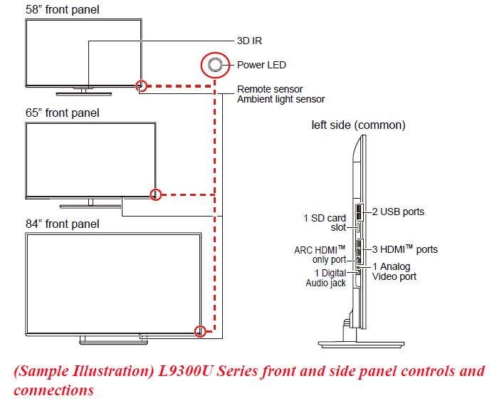
TV front and side panel controls and connections
Front panel
- Power On/Standby LED—Power indicator light (glows green when the TV power is On).
- Ambient light sensor—This sensor detects the ambient light conditions to optimize the backlighting levels, see “Ambient Light Sensor” on page 116.
- Remote Sensor—Point the remote control toward this remote sensor. See “Remote control effective range” on page 52.
- 3D IR—This sensor detects the 3D IR (for 58L9300U model only).
Left side
- Analog Video Port—Analog Video input. Connect using a commercially available conversion cable.
- 3 HDMI™ Ports—High-Definition Multimedia Interface input receives digital audio and uncompressed digital video from an HDMI™ device or uncompressed digital video from a DVI device. An HDMI™ connection is necessary to receive 1080p and 4K signals. 7 ARC HDMI™ only port—Audio Return Channel (ARC) enables the audio signal of the TV to be sent to an AV amplifier via the HDMI cable.
- Digital Audio Jack—Optical audio output in Dolby® Digital or PCM (pulse-code modulation) format for connecting an external Dolby® Digital decoder, amplifier, A/V receiver, or home theater system with optical audio input.
- 2 USB Ports—Used to access video, music, or photo files with a USB device. Works with the wireless keyboard.
- SD card slot—Used to access video, music, or photo files with an SD card.
TV back panel controls and connections
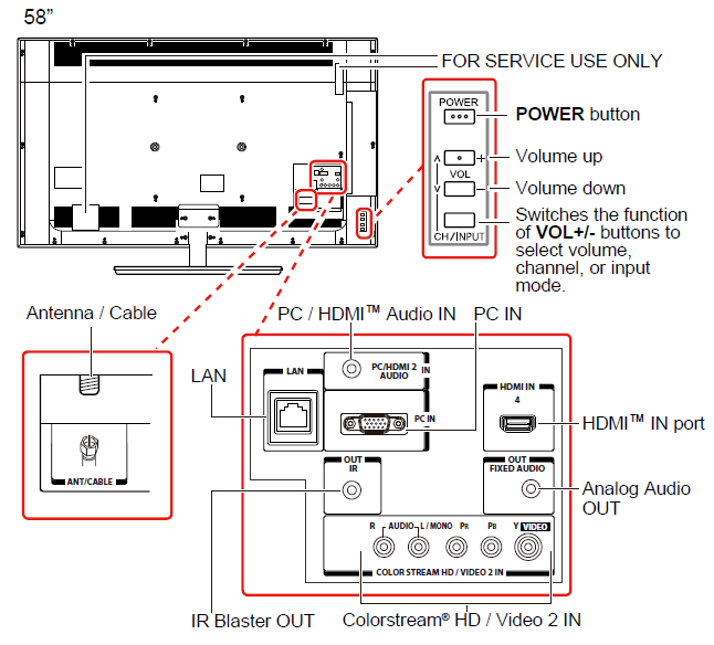
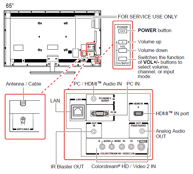
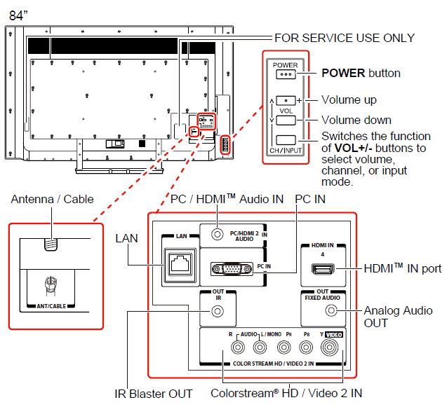
(Sample Illustration) L9300U Series back panel controls and connections
For explanations of cable types and connections, see “Connecting Your TV” on page 29.
Back panel controls
- POWER—Turns the TV On and Off.
- VOL +/– —Adjust the volume level, change the channel, or change the input or source you are viewing, depending on the mode, which is selected by the CH/INPUT button.
- CH / INPUT — Switches the function of the VOL +/– buttons to select the volume, channel, or input mode.
- In Volume mode, the arrow buttons increase or decrease the volume.
- In Channel mode, the arrow buttons change the channel up or down.
- In Source mode, the arrow buttons toggle the input from one source to the next. The mode of the VOL +/– buttons changes in the following order each time the button is pressed:
→ Channel → Input → Volume →
Back panel connections
- LAN IN —Connects the TV to your home network.
- HDMI™ IN—High-Definition Multimedia Interface input receives digital audio and uncompressed digital video from an HDMI™ device or uncompressed digital video from a DVI device. HDMI™ connection is necessary to receive 1080p and 4K signals.
- Analog Audio Port—Analog audio outputs for connecting an audio amplifier.
- PC IN —For use when connecting a personal computer.
- ANT/CABLE —Antenna input that supports analog (NTSC) and digital (ATSC) off-air antenna signals and analog and digital Cable TV (QAM) signals.
- ColorStream® HD/ Video 2 IN —These include standard A/V connections, see “Connecting DVD to ColorStream® or VCR to composite video” on page 34.
- PC/HDMI™ Audio IN —PC audio input terminals are shared with HDMI™-2 analog audio input terminals, and their use can be configured in the Configuring shared inputs menu, see “Configuring shared input” on page 72.
- IR Blaster OUT —Used to connect and control infrared remote-controlled devices.
- FOR SERVICE USE ONLY―Connectors for service use only.
NOTE Component/Standard (composite) video cables carry only video information; separate audio cables are required.
Connecting Your TV
Overview of cable types
Before purchasing cables, know the connector types your devices require. You can purchase cables from most stores that sell audio/video devices.
Coaxial cable (F-type)

Coaxial (F-type) cable connects your antenna, cable TV service, and/or cable converter box to the ANT/CABLE input on your TV.
NOTE: Please tighten this connection by hand. Using tools may damage the connection.
Standard AV cables (red/white/yellow)
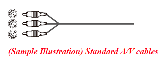
Standard A/V cables (composite video) usually come in sets of three, and connect to video devices with analog audio and composite video output. These cables (and the related inputs on your TV) are typically color-coded according to use: yellow for video, red for stereo right audio, and white for stereo left (or mono) audio.
Component video cables (red/green/blue)
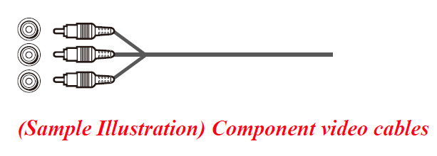
Component video cables come in sets of three and are for use with video devices with component video output. (ColorStream® is Toshiba’s brand of component video.) These cables are typically color-coded red, green, and blue. Separate audio cables are required for a complete connection.
NOTE: Component video cables provide better picture quality than composite video cables.
HDMI™ cable (with HDMI Logo)
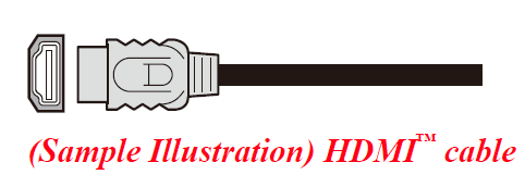
HDMI™ (High-Definition Multimedia Interface) cable connects to devices that have an HDMI™ output. An HDMI™ cable delivers digital audio and video in its native format. Separate audio cables are not required; see “Connect a computer to the TV’s HDMI™ terminal” on page 44.
NOTE: HDMI™ cables provide the best audio and picture quality.
Dual-wand IR blaster cable
Connect the dual-wand IR blaster cable to the IR blaster terminal to control infrared remote-controlled devices from the TV.
Optical audio cable

Optical audio cable connects receivers with Dolby® Digital or PCM (pulse-code modulation) optical audio input to the TV’s Digital Audio Out terminal, see “Connecting a digital audio system” on page 38.
Analog RGB (15-pin) computer cable

Analog RGB (15-pin) computer cable connects a computer to the TV’s PC IN terminal, see “Connecting a computer to the TV’s PC IN terminal” on page 43.
NOTE: Separate audio cables are required.
3.5mm Stereo to RCA Y-cable

3.5mm Stereo to RCA Y-cable connects an audio signal from a DVI device to a TV.
LAN cable

Standard LAN cable connects the TV to your home network; see “Connecting the TV to a home network with an Internet connection – wired” on page 47.
Crossover LAN cable connects the TV directly to a computer; see “Connecting the TV directly to a computer without an Internet connection” on page 45.
About the connection illustrations
You can connect different types and brands of devices to your TV in several different configurations. The connection illustrations in this manual are representative of typical device connections only. The input/output terminals on your devices may differ from those illustrated. For details on connecting and using your specific devices, refer to each device’s owner’s manual.
Connecting an antenna, satellite receiver, and/or cable TV box
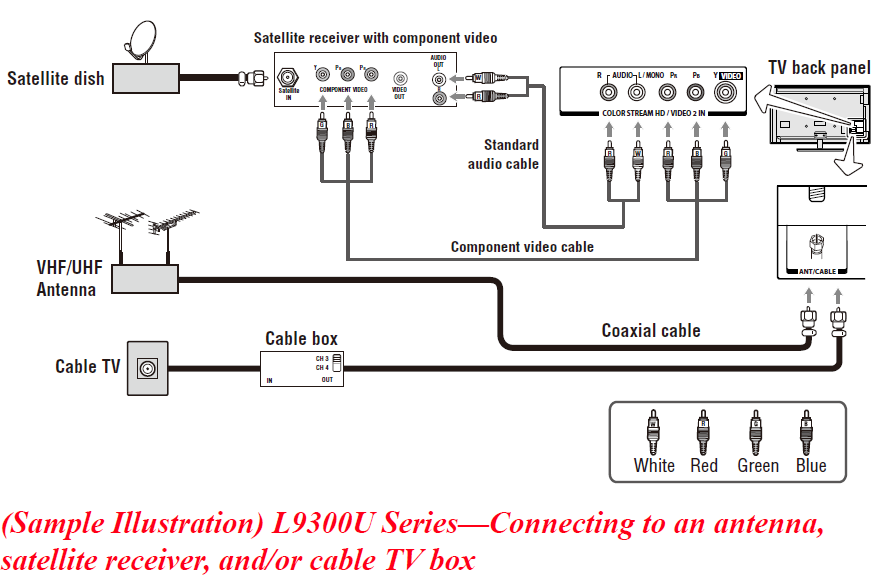
Items needed
- Coaxial cables
- Standard AV cables
- Component video cables (red/green/blue)
NOTE: When you use a cable box, you may not be able to use the remote control to program or access certain features on the TV.
To view the antenna or cable signal
Select the ANT/CABLE video input source on the TV.*
To view basic and premium cable channels
Select the ANT/CABLE video input source on the TV.* Tune the TV to channel 3 or 4 (whichever channel the cable box output is set to). Use the cable box controls to change channels.
To view the VCR or camcorder video
Turn on the VCR or camcorder video. Select the VIDEO input source on the TV.*
*To select the video input source, press the INPUT button on the remote control, see “Selecting the video input to view” on page 85.
NOTE:
The unauthorized recording, use, distribution, or revision of television programs, videotapes, DVDs, and other materials is prohibited under the Copyright Laws of the United States and other countries, and may subject you to civil and criminal liability.
Connecting a DVD to ColorStream® or a VCR to composite video
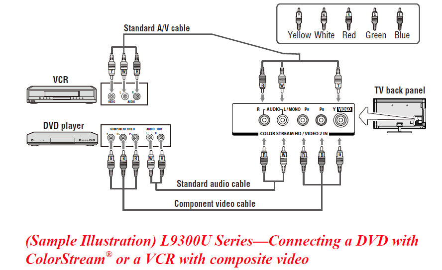
Items needed
- Coaxial cables
- Standard AV cables
- Standard audio cables
- Composite or component video cables
- You can connect the component video cables (plus audio cables) from the DVD player or satellite receiver to the COLOR STREAM HD terminal in the TV. The COLOR STREAM HD terminal can be used to display Progressive (480p, 720p, 1080p) and Interlaced (480i, 1080i) scan systems. If your DVD player or satellite receiver does not have component video, connect a standard A/V cable to the AUDIO/ VIDEO terminal. If your DVD player has HDMI™ video, see “Connecting an HDMI™ or DVI device to the HDMI™ input” on page 39.
NOTE: When you use ColorStream® HD or Video, please switch to the appropriate AV mode.
- You can connect the component video cables (plus audio cables) from the DVD player or satellite receiver to the COLOR STREAM HD terminal in the TV. The COLOR STREAM HD terminal can be used to display Progressive (480p, 720p, 1080p) and Interlaced (480i, 1080i) scan systems. If your DVD player or satellite receiver does not have component video, connect a standard A/V cable to the AUDIO/ VIDEO terminal. If your DVD player has HDMI™ video, see “Connecting an HDMI™ or DVI device to the HDMI™ input” on page 39.
To view antenna or Cable channels
Select the ANT/CABLE video input source on the TV.*
To view the DVD player
Turn ON the DVD player. Select the ColorStream® HD video input source on the TV.*
To view satellite programs using the component video connections
Turn ON the satellite receiver. Select the ColorStream® HD video input source on the TV.*
To view the VCR or view and record antenna channels
Turn ON the VCR. Tune the VCR to the channel you want to watch. Select the VIDEO video input source on the TV.*
To record a TV program while watching a DVD
Turn ON the VCR. Tune the VCR to the channel to record. Select the ColorStream® HD video input source on the TV* to view the DVD.
*To select the video input source, press the INPUT button on the remote control, see “Selecting the video input to view” on page 85.
NOTE: The unauthorized recording, use, distribution, or revision of television programs, videotapes, DVDs, and other materials is prohibited under the Copyright Laws of the United States and other countries, and may subject you to civil and criminal liability.
Connecting remote IR devices
Using the IR blaster OUT terminal
You can use the TV’s IR OUT terminal to remotely operate many infrared remote-controlled devices enclosed in an entertainment center or similar cabinet.
Items needed
- Dual-wand IR blaster cable (see “Dual-wand IR blaster cable” on page 30)
- Other cables as required to connect the device(s) to the TV (see “Overview of cable types” on page 29)
See the remote IR blaster setup section (see page 61).
To connect the IR blaster cable
- Locate the infrared sensor on the front of your device. This sensor is marked on some devices. If you are having issues locating the device’s infrared sensor, see “If you cannot locate the device’s infrared sensor” on page 37.
- Align one of the IR blaster cable’s wands approximately 1 inch away from the infrared sensor on the front of the device and attach it using double-sided mounting tape. If you have a second device, attach the second wand similarly.
NOTE: If you do not have a second device, coil the second wand with a rubber band and leave it behind the TV. - Plug the IR blaster cable’s plug into the TV’s IR Blaster Out terminal.
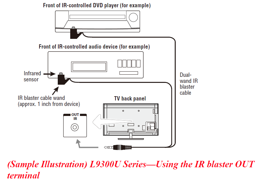
To control the device(s)
Point the TV remote control toward the front of the TV and press the button for the desired function. The signal passes from the remote control through the TV to the device via the IR Blaster cable. For more information, see “Setting the IR Blaster” on page 61.
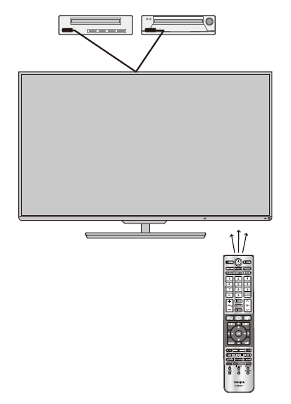
(Sample Illustration) Controlling the device(s) – remote control
NOTE: The IR pass-through feature does not support all IR-controlled devices. Satisfactory quality may not be attainable with certain devices.
If you cannot locate the device’s infrared sensor
- Turn off the device.
- Starting at the device’s lower-left corner, place the end of the device’s remote control (with the infrared emitter) so it touches the front of the device. Press the POWER button. (Do not use the TV’s remote control for this step.)
- If the device turns on, the sensor is located where the remote control touched the device.
- If the device does not turn on, move the remote control slightly to the right and press the POWER button again.
- Repeat the previous steps if necessary.
Connecting a digital audio system
The TV’s Digital Audio Out terminal outputs a Dolby® Digital or 2-channel down-mixed PCM (pulse-code modulation) signal for use with an external Dolby® Digital decoder or other external audio systems with optical audio input.
You will need an Optical audio cable (Use an optical audio cable that has the larger “TosLink” connector and not the smaller “mini-optical” connector.)
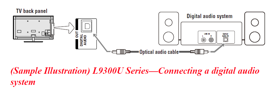
Before controlling the audio, see “Selecting the optical audio output format” on page 123.
NOTE: Some audio systems may not be compatible with Dolby® Digital bitstream signals. Older audio systems that are not compatible with standard optical out signals may not work properly, creating a high noise level that may damage speakers or headphones. THIS DAMAGE IS NOT COVERED BY YOUR WARRANTY. The DIGITAL AUDIO OUT terminal may not output some digital audio sources because of copy restrictions.
- The Dolby® Digital format is available in the following situations:
- When tuned to a digital RF channel
- When an HDMI™ input is used
- When network devices are used
Connecting an HDMI™ or DVI device to the HDMI™ input
The HDMI™ input on your TV receives digital audio and uncompressed digital video from an HDMI™ source device, or uncompressed digital video from a DVI (Digital Visual Interface) source device. This input is designed to accept HDCP (High-Bandwidth Digital-Content Protection) program material in digital form from EIA/CCEA–861–D–compliant 1 consumer electronic devices (such as a set-top box or DVD player with HDMI™ or DVI output).
The HDMI™ input can accept and display VGA, SVGA, XGA, WXGA, SXGA, 480i (60Hz), 480p (60Hz), 720p (60Hz), 1080i (60Hz), 1080p (24Hz/30Hz/60Hz), and 4K video signal formats. For detailed signal specifications, see “HDMI™ signal formats” on page 191 and “4K Video Support formats” on page 192. The supported Audio formats are Linear PCM and Dolby® Digital, sampling rate 32/44.1/ 48 kHz.
NOTE: To connect a PC to the HDMI™ input, see “Connect a computer to the TV’s HDMI™ terminal” on page 44.
We cannot guarantee that all 4K video input through HDMI terminals will be displayed. To connect an HDMI™ device, you will need one HDMI™ cable (type A connector) per HDMI™ device:
- For proper operation, it is recommended that you use an HDMI™ cable with the HDMI™ Logo (
 ).
). - To display a 1080p/60Hz and 4K signal format, you will need a High Speed HDMI™ cable. A conventional HDMI™/DVI cable may not work properly.
- HDMI™ cables transfer both video and audio. Separate analog audio cables are not required (see illustration).
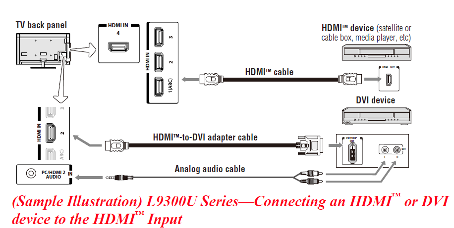
To view the HDMI™ device video
Select HDMI 1, HDMI 2, HDMI 3, and HDMI 4 video input sources on the TV. (Press the INPUT button on the remote control. For more information, see “Selecting the video input to view” on page 85.
To connect a DVI device, you will need
- HDMI™ to DVI adapter cable
For proper operation, the length of an HDMI™ to DVI adapter cable should not exceed 9.8 ft (3m). The recommended length is 6.6 ft (2m). - 3.5mm Stereo to RCA Y-cable
An HDMI™ to DVI adapter cable transfers video only. Separate analog audio cables are required (see illustration).
NOTE: To ensure that the HDMI™ or DVI device is reset properly:
- When turning on your electronic components, turn on the TV first, and then the HDMI™ or DVI device.
- When turning off your electronic components, turn off the HDMI™ or DVI device first, and then the TV.
NOTE: [1] EIA/CEA-861-D compliance covers the transmission of uncompressed digital video with high-bandwidth digital content protection, which is being standardized for reception of high definition video signals. Because this is an evolving technology, it is possible that some devices may not operate properly with the TV.
Using the TV remote and HDMI™ CEC Control to control other devices
To control the basic functions of connected audio/video devices using the TV’s remote control, connect an HDMI™ CEC-compatible audio system or playback device. The HDMI™ CEC Control feature uses CEC technology as regulated by the HDMI™ standard.
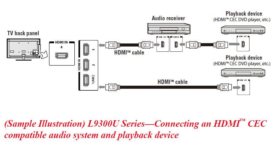
To connect an audio system and playback devices, you will need HDMI™ cables, see “HDMI™ cable (with HDMI Logo)” on page 30.
NOTE: If several devices are connected, the HDMI™ CEC Control feature may not operate properly, see “HDMI™ CEC Control input source selection” on page 97.
For proper operation, it is recommended that you use HDMI™ cables with the HDMI™ Logo (![]() ).
).
- HDMI™ CEC devices can be controlled by the TV remote only when it is in the TV mode.
Before controlling the devices
- For an explanation of setup and operations, see “Other HDMI™ CEC Control functions” on page 98.
- Configure the connected devices. See each device’s operation manual.
NOTE: This feature is limited to models incorporating Toshiba’s HDMI™ CEC Control feature. However, Toshiba is not liable for those operations. See the individual instruction manuals for compatibility information.
When using an external AV amplifier, the picture and sound may not be properly synchronized. In this case, adjust the delay time of the sound on the AV amplifier.
NOTE: The control range of the delay time differs according to the device you use.
For more manuals by Toshiba, visit ManualsLibraryy

