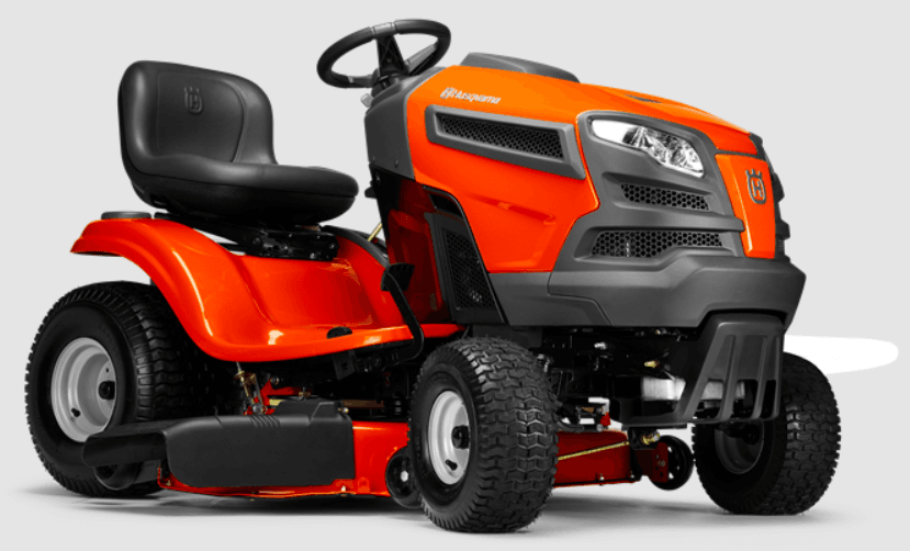
Husqvarna YTH 2448 Garden Tractor
ASSEMBLY
- Your new tractor has been assembled at the factory with the exception of those parts left unassembled for shipping purposes. To ensure the safe and proper operation of your tractor all parts and hardware you assemble must be tightened securely. Use the correct tools as necessary to insure proper tightness.
TOOLS REQUIRED FOR ASSEMBLY
A socket wrench set will make assembly easier. Standard wrench sizes are listed.
- (1) Tire pressure gauge
- (2) 3/4″ wrenches (1) Utility knife
- (2) 7/16″ wrenches (1) 3/4″ socket w/drive ratch et
- (1) Pliers
- When the right or left hand is mentioned in this manual, it means when you are in the operating position (seated behind the steering wheel)
TO REMOVE THE TRACTOR FROM THE CARTON
UNPACK CARTON
- Remove all accessible loose parts and parts cartons from a carton.
- Cut along dotted lines on all four panels of the carton. Remove end panels and lay side panels flat.
- Remove the mower and packing materials.
- Check for any additional loose parts or cartons and remove them.

BEFORE REMOVING TRAC TOR FROM SKID
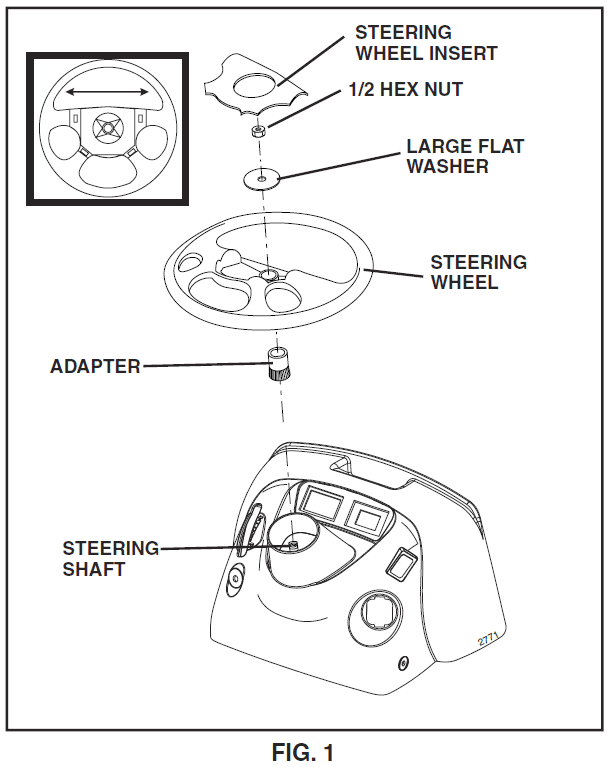
ATTACH STEERING WHEEL (See Fig. 1)
- Remove the locknut and large flat washer from the steering shaft.
- Position the front wheels of the tractor so they are pointing straight forward.
- Position the steering wheel so the cross bars are horizontal (left to right) and slide onto the steering wheel adapter.
- Secure steering wheel to steering shaft with locknut and large fl at wash er pre vi ous ly removed. Tight en securely.
- Snap the steering wheel inserted into the center of the steering wheel.
- Remove protective materials from the tractor hood and grill.
- IMPORTANT: CHECK FOR AND REMOVE ANY STAPLES IN THE SKID THAT MAY PUNCTURE TIRES WHERE THE TRACTOR IS TO ROLL OFF SKID.
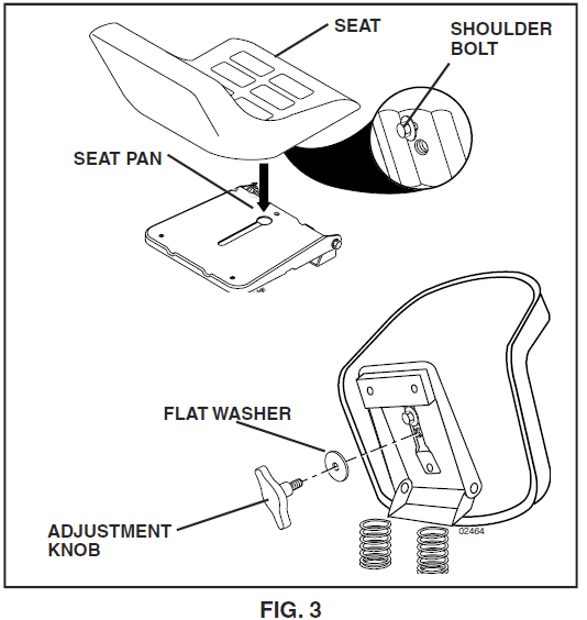
INSTALL SEAT (See Fig. 3)
Adjust the seat before tightening the adjustment knob.
- Remove adjustment knob and fl at washer securing seat to cardboard packing and set aside for assembly of seat to tractor.
- Pivot the seat upward and remove it from the cardboard packing. Remove the cardboard packing and discard.
- Place the seat on seat pan so the head of the shoulder bolt is positioned over a large slotted hole in the pan.
- Push down on the seat to engage the shoulder bolt in the slot and pull the seat towards the rear of the tractor.
- Pivot the seat and pan forward and assemble the adjustment knob and flat the washer loosely. Do not tighten.
- Lower the seat into the operating position and sit on the seat.
- Slide the seat until a comfortable position is reached which allows you to press the clutch/brake pedal all the way down.
- Get off your seat without moving its adjusted position.
- Raise the seat and tighten the adjustment knob securely.

TO DRIVE TRACTOR OFF SKID (See Operation section for location and function of controls)
WARNING: Before starting, read, understand, and follow all of the structures in the Operation section of this manual. Be sure the tractor is in a well-ventilated area. Be sure the area in front of the tractor is clear of other people and objects.
- Be sure all the above assembly steps have been completed.
- Check engine oil level and fill the fuel tank with gasoline.
- Place freewheel control in the “transmis sion engaged” position (see “TO TRANSPORT” in the Operation section of this manual).
- Sit on the seat in the operating position, depress the clutch/brake pedal, and set the parking brake.
- Place the motion control lever in the neutral (N) position.
- Press the lift lever plunger and raise the attachment lift lever to its highest position.
- Start the engine. After the engine has started, move the throttle control to idle position.
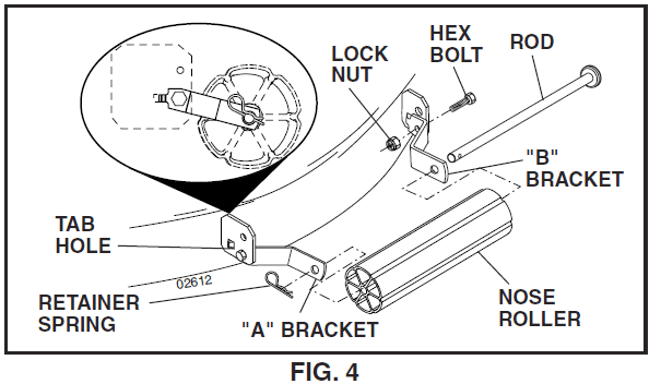
TO ATTACH NOSE ROLLER (See Fig. 4)
- Assemble brackets “A” and “B” to the inside of the mower mounting brackets as shown. Tighten securely.
NOTE: Be sure bracket tabs are positioned in tab holes in mower brackets. - Position the nose roller between brackets and install the rod and retainer spring.

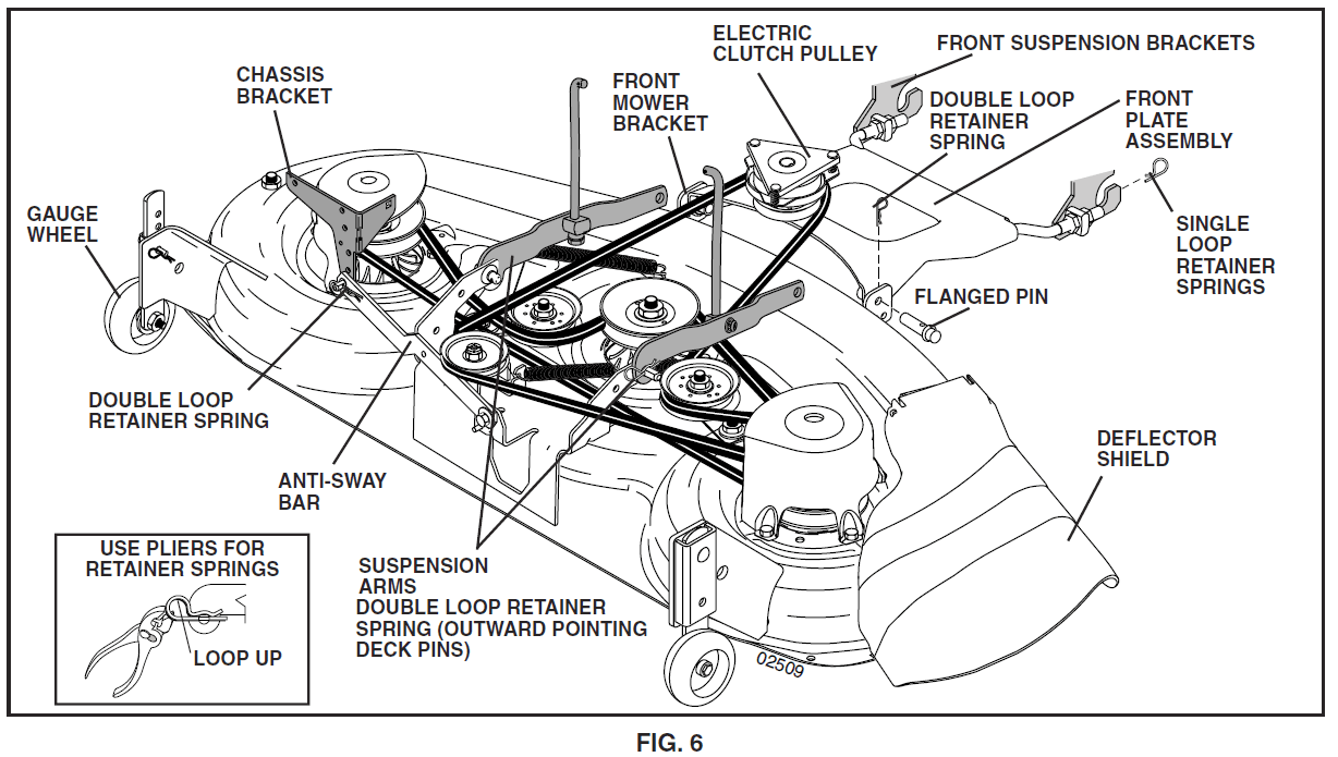
INSTALL MOWER AND DRIVE BELT (See Figs. 6 and 7)
Be sure the tractor is on a level surface and mower suspension arms are raised with attachment lift control. Engage parking brake.
- Cut and remove ties securing anti-sway bars and belts. Swing the anti-sway bar to the left side of the mower deck.
- Slide mower under tractor with deflector shield to right side of tractor.
- IMPORTANT: Check the belt for proper routing in all mower pulley grooves.
- If equipped, turn the height adjustment knob counter-clockwise until it stops.
- Lower mower linkage with attachment lift control.
- Install belt into electric clutch pulley groove.
- Place the suspension arms on outward-pointing deck pins. Retain with double loop retainer spring with loops up as shown.
- Install front plate assembly to tractor suspension brackets and retain with single loop retainer springs as shown.
- Position front plate assembly between front mower brackets. Raise deck and plate assembly to align holes and insert flanged pins. Secure pins with double loop
retainer springs between the plate and mower brackets. - NOTE: To assist in locating the hole in the flanged pin, the hole in the pin is inline with a notch on the head of the pin. If necessary, move the mower side-to-side to give space between plate and mower brackets.

- CHECK TIRE PRESSURE
- The tires on your tractor were overinfl ated at the factory for shipping purposes. Correct tire pressure is important for best cutting performance.
- Reduce tire pressure to PSI shown in “PRODUCT SPEC I FI CA TIONS” section of this manual.
- CHECK MOWER LEVELNESS
- For best cutting results, mower should be properly leveled. See “TO LEVEL MOWER HOUSING” in the Service and Adjustments section of this manual.
- CHECK FOR PROPER POSITION OF ALL BELTS
- See the fi gures that are shown for replacing motion, mower drive, and mower blade drive belts in the Service and Adjustments section of this manual. Verify that the belts are routed correctly.
- CHECK BRAKE SYSTEM
- After you learn how to operate your tractor, check to see that the brake is properly adjusted. See “TO ADJUST BRAKE” in the Service and Adjustments section of this manual
OPERATION
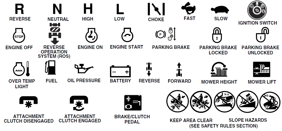
KNOW YOUR TRACTOR
READ THIS OWNER’S MANUAL AND SAFETY RULES BEFORE OPERATING YOUR TRACTOR
Compare the illustrations with your tractor to familiarize yourself with the locations of various controls and adjustments. Save this manual for future reference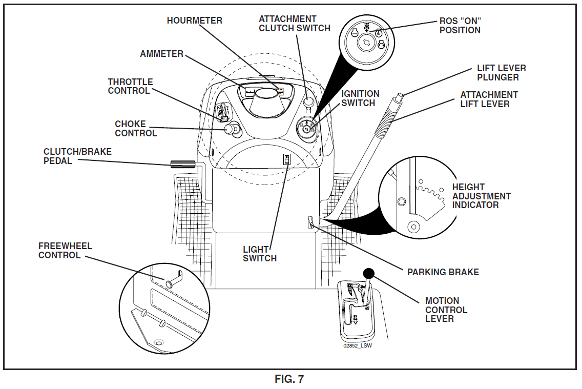
Our tractors conform to the applicable safety standards of the American National Standards Institute.
- AMMETER – Indicates charging (+) or discharging (-) of battery.
- ATTACHMENT CLUTCH SWITCH – Used to engage the mower blades, or other attachments mounted to your tractor.
- ATTACHMENT LIFT LEVER – Used to raise, lower and adjust the mower deck or other attachments mounted to your tractor.
- CHOKE CONTROL – Used when starting a cold engine.
- CLUTCH/BRAKE PEDAL – Used for declutching and brak ing the tractor and starting the engine.
- FREE WHEEL CONTROL – Disengages transmission for pushing or slowly towing the tractor with the engine off.
- HOUR METER– Indicates hours of operation
- IGNITION SWITCH – Used for starting and stopping the engine.
- LIFT LEVER PLUNGER – Used to release attachment lift lever when changing its position.
- LIGHT SWITCH – Turns the headlights on.
- MOTION CONTROL LEVER – Selects the speed and direction of tractor.
- PARKING BRAKE – Locks clutch/brake pedal into the brake position.
- REVERSE OPERATION SYSTEM (ROS) “ON” POSITION Allows operation of mower deck or other powered attachment while in reverse.
- THROTTLE CONTROL – Used to control engine speed.
HOW TO USE YOUR TRACTOR TO SET THE PARKING BRAKE
Your tractor is equipped with an operator presence-sensing switch. When the engine is running, any attempt by the operator to leave the seat without first setting the parking brake will shut off the engine.
- Depress clutch/brake pedal (B) all the way down and hold.
- Pull the parking brake lever (C) up and hold, release pressure from clutch/ brake pedal (B), then release the parking brake lever. The pedal should remain in the brake position. Make sure the parking brake will hold the tractor secure.

STOPPING
MOWER BLADES
- To stop the mower blades, move attachment clutch clutch lever to the disengaged position (o)
GROUND DRIVE
- To stop the ground drive, depress the clutch/ brake pedal all the way down.
- Move the motion control lever (J) to the neutral position.
- ENGINE
- Move throttle control (D) between half and full speed (fast) position.
NOTE: Failure to move throttle control between half and full speed (fast) position, before stopping, may cause the engine to “backfire”. - Turn the ignition key (F) to the “STOP” position and remove the key. Always remove the key when leaving the tractor to prevent unauthorized use.
- Never use choke (N) to stop the engine.
IMPORTANT: Leaving the ignition switch in any position other than “STOP” will cause the battery to discharge and go dead.
NOTE: Under certain conditions when tractor is standing idle with the engine running, hot engine exhaust gases may cause the “browning” of grass. To eliminate this possibility, always stop the engine when stopping the tractor on grass areas. - CAUTION: Always stop the tractor completely, as described above, and set the parking brake before leaving the operator’s position.
TO USE THROTTLE CONTROL
Always operate the engine at full speed (fast).
- Operating the engine at less than full speed (fast) reduces the engine’s operating efficiency.
- Full speed (fast) offers the best mower performance.
TO USE CHOKE CONTROL
- Use choke control whenever you are starting a cold engine. Do not use it to start a warm engine.
- To engage choke control, pull the knob out. Slowly push the knob in to disengage.
TO MOVE FORWARD AND BACKWARD
The direction and speed of movement is controlled by the motion control lever.
- Start tractor with motion control lever in neutral (N) position.
- Release parking brake.
- Slowly move the motion control lever to the desired position.
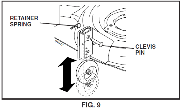
TO ADJUST GAUGE WHEELS
Gauge wheels are properly adjusted when they are slightly off the ground when the mower is at the desired cutting height in the operating position. Gauge wheels then keep the deck in the proper position to help prevent scalping in most terrain conditions.
NOTE: Adjust gauge wheels with the tractor on a flat-level surface.
- Adjust the mower to the desired cutting height (See “TO ADJUST MOWER CUTTING HEIGHT” in this section of the manual).
- Remove retainer spring and clevis pin which secure each gauge wheel bar.
- Lower gauge wheels to ground. Raise gauge wheels slightly to align holes in bracket and gauge wheel bar and insert clevis pin. Gauge wheels should be slightly
off the ground. - Replace retainer spring into clevis pin.
- Be sure all gauge wheels are in the same setting.
- IMPORTANT: BE SURE TO READJUST GAUGE WHEELS IF YOU CHANGE THE CUTTING HEIGHT OF THE MOWER DECK.

- IMPORTANT: BE SURE TO READJUST GAUGE WHEELS IF YOU CHANGE THE CUTTING HEIGHT OF THE MOWER DECK.
TO OPERATE MOWER
Your tractor is equipped with an operator presence-sensing switch. Any attempt by the operator to leave the seat with the engine running and the attachment clutch engaged will shut off the engine. You must
remain fully and centrally positioned in the seat to prevent the engine from hesitating or cutting off when operating your equipment on rough, rolling terrain or hills.
- Select the desired height of the cut with the attachment lift lever.
- Start mower blades by engaging the attachment clutch control.
TO STOP MOWER BLADES – disengage attachment clutch control.
CAUTION: Do not operate the mower without either the entire grass catcher, on mowers so equipped, or the deflector shield in place.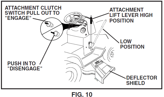
REVERSE OPERATION SYSTEM (ROS)
- Your tractor is equipped with a Reverse Operation System (ROS). Any attempt by the operator to travel in the reverse direction with the attachment clutch engaged will shut off the engine unless ignition key
is placed in the ROS “ON” position. - WARNING: Backing up with the attachment clutch engaged while mowing is strongly discouraged. Turning the ROS “ON”, to allow reverse operation with the attachment clutch engaged, should only be done when the operator decides it is necessary to reposition the machine with the attachment engaged. Do not mow in reverse unless absolutely necessary.
USING THE REVERSE OPERATION SYSTEM –
Only use if you are certain no children or other bystanders will enter the mowing area.
- Move motion control lever to neutral (N) position.
- With engine running, turn ignition key counterclockwise to ROS “ON” position.
- Look down and behind before and while backing.
- Slowly move motion control lever to reverse (R) position to start movement.
- When use of the ROS is no longer needed, turn the ignition key clockwise to engine “ON” position.
ROS “ON” Position

Engine “ON” Position (Normal Operating)

TO OPERATE ON HILLS
WARNING: Do not drive up or down hills with slopes greater than 15 ° and do not drive across any slope. Use the slope guide provided at the back of this manual.
- Choose the slowest speed before starting up or down hills.
- Avoid stopping or changing speed on hills.
- If stopping is absolutely necessary, push the clutch/brake pedal quickly to the brake position and engage parking brake.
- To restart movement, slowly release the parking brake and clutch/brake pedal.
- Slowly move motion control lever to slowest setting.
- Make all turns slowly.
TO TRANSPORT
When pushing or towing your tractor, be sure to disengage the transmission by placing freewheel control in the freewheeling position. Freewheel control is located at the rear drawbar of tractor.
- Raise attachment lift lever to its highest position
- Pull freewheel control out and into the slot and release so it is held in the disengaged position
- Do not push or tow tractor at more than two (2) MPH
- To re-engage transmission, reverse above procedure.
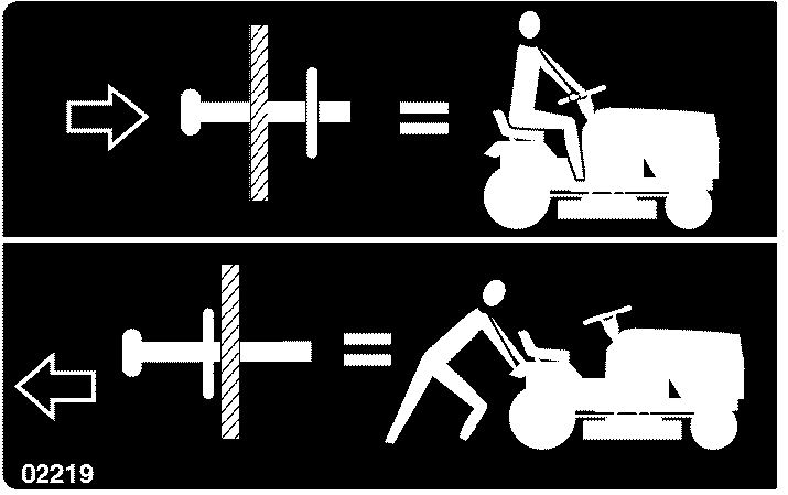
NOTE: To protect hood from damage when transporting your tractor on a truck or a trailer, be sure hood is closed and secured to tractor. Use an appropriate means of tying hood to tractor (rope, cord, etc.).
MAINTENANCE
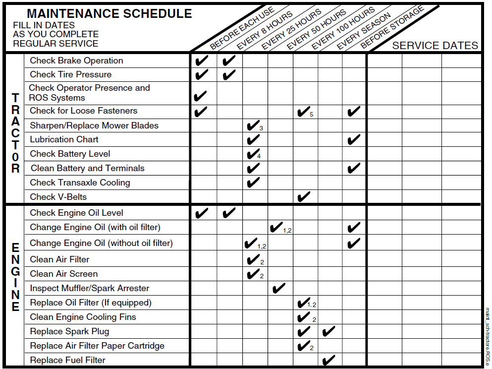
- Change more often when operating under a heavy load or in high ambient temperatures.
- Service more often when operating in dirty or dusty conditions.
- Replace blades more often when mowing in sandy soil.
- Not required if equipped with a maintenance-free battery.
- Tighten front axle pivot bolt to 35 ft.-lbs. maximum. Do not overtighten
GENERAL RECOMMENDATIONS
The warranty on this tractor does not cover items that have been subjected to operator abuse or negligence. To receive full value from the warranty, an operator must maintain the tractor as instructed in this
manual. Some adjustments will need to be made periodically to properly maintain your tractor. At least once a season, check to see if you should make any of the adjustments described in the Service and Adjustments section of this manual.
- At least once a year you should replace the spark plug, clean or replace air filter, and check blades and belts for wear. A new spark plug and clean air filter assure proper air-fuel mixture and help your engine run better and last longer.
BEFORE EACH USE
- Check engine oil level.
- Check brake operation.
- Check tire pressure.
- Check operator presence and ROS systems for proper operation.
- Check for loose fasteners.
LUBRICATION CHART

- General Purpose Grease
- Refer to Maintenance “ENGINE” Section
SERVICE AND ADJUSTMENTS
TRACTOR
TO REMOVE MOWER (See Fig. 18)
- Place attachment clutch in “DIS EN GAGED” position.
- If equipped, turn height adjustment knob to lowest setting.
- Lower mower to its lowest position.
- Remove retainer spring holding anti-swaybar to chassis bracket and dis en gage anti-swaybar from bracket.
- Remove four retainer springs from front plate assembly and remove plate.
- Remove retainer springs from sus pen sion arms at deck and disengage arms from deck.
- Raise attachment lift to its highest position.
- Slide mower forward and remove belt from electric clutch pulley.
- Slide mower out from under right side of tractor.
TO INSTALL MOWER
Be sure tractor is on level surface and mower suspension arms are raised with attachment lift control. Engage parking brake.
- Swing anti-sway bar to left side of mower deck.
- Slide mower under tractor with defl ector shield to right side of tractor.
- IMPORTANT: CHECK BELT FOR PROPER ROUTING IN ALL MOWER PULLEY GROOVES.
- If equipped, turn height ad just ment knob counter -clock wise until it stops.
- Lower mower linkage with attachment lift control.
- Install belt into electric clutch pulley groove.
- Place the suspension arms on outward pointing deck pins. Retain with double loop re tain er spring with loops up as shown.
- Install front plate assembly to tractor suspension brackets and retain with single loop retainer springs as shown

STORAGE
TRACTOR
Remove mower from tractor for winter storage. When mower is to be stored for a period of time, clean it thor oughly, remove all dirt, grease, leaves, etc. Store in a clean, dry area.
- Clean entire tractor (See “CLEANING” in the Maintenance section of this manual).
- Inspect and replace belts, if necessary (See belt replacement instructions in the Service and Adjustments section of this manual).
- Lubricate as shown in the Maintenance section of this manual.
- Be sure that all nuts, bolts and screws are securely fastened. Inspect moving parts for damage, breakage and wear. Replace if necessary.
- Touch up all rusted or chipped paint surfaces; sand lightly before painting.
- ENGINE
- FUEL SYSTEM
- IMPORTANT: IT IS IMPORTANT TO PREVENT GUM DEPOSITS FROM FORMING IN ES SEN TIAL FUEL SYSTEM PARTS SUCH AS CARBURETOR, FUEL FIL TER, FUEL HOSE, OR TANK DURING STORAGE. ALSO, EXPERIENCE INDICATES THAT ALCOHOL BLENDED FUELS (CALLED GASOHOL OR USING ETHANOL OR METHANOL) CAN ATTRACT MOIS TURE WHICH LEADS TO SEPARATION AND FOR MA TION OF ACIDS DURING STORAGE. ACIDIC GAS CAN DAMAGE THE FUEL SYSTEM OF AN ENGINE WHILE IN STORAGE
- ENGINE OIL
- Drain oil (with engine warm) and replace with clean engine oil. (See “ENGINE” in the Maintenance section of this man ual).
- CYLINDER(S)
- Remove spark plug(s).
- Pour one ounce of oil through spark plug hole(s) into cylinder(s).
- Turn ignition key to “START” position for a few seconds to distribute oil.
- Replace with new spark plug(s).
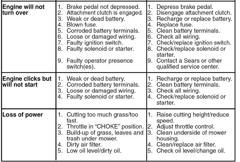
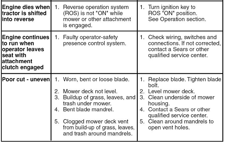
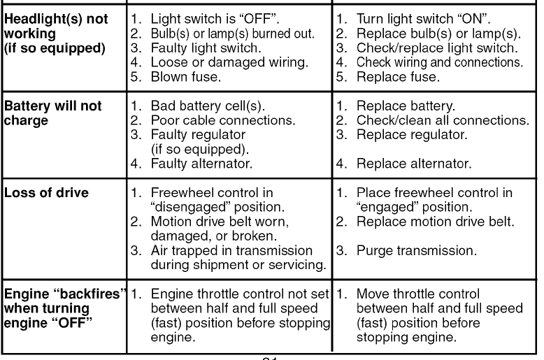
TROUBLESHOOTING CHART:
- See appropriate section in manual unless directed to Sears service center



For more manuals by Husqvarna, visit ManualsLibraryy
Husqvarna YTH 2448 Garden Tractor-FAQs
How long does a Husqvarna lawn tractor last?
The lifespan depends on usage. With regular use, a Husqvarna riding mower can last 600-800 hours, while occasional use can extend its life to 1,500 hours or more.
What type of fuel does the Husqvarna YTH 2448 use?
This tractor is designed to run on gasoline with up to 10% ethanol (E10). Using fuel with more than 10% ethanol may void the warranty.
How often should I change the oil in my Husqvarna lawn tractor?
Check the oil level every 5 hours of continuous use and change the oil at least once per season to maintain optimal performance.
How can I determine the age of my Husqvarna tractor?
You can identify the age by checking the engine serial number, which may also be required when ordering replacement parts.
Where can I find the model number of my Husqvarna tractor?
The model number is printed on the logo label or can be found on the product’s ID tag.
What type of transmission does the Husqvarna YTH 2448 have?
The Husqvarna YTH 2448 comes with a hydrostatic transmission, which provides smooth and variable speed control.
How often should I replace the spark plugs on my Husqvarna riding mower?
Spark plugs should be replaced every 25 to 30 hours of operation to ensure reliable performance.
When should I change the engine oil?
Typically, engine oil should be changed every 5,000 to 7,500 miles, but factors like engine type and usage may require more frequent changes.
Where is Husqvarna manufactured?
Husqvarna was originally founded in Sweden, where the first factory was established in the town of Huskvarna to produce military equipment.


