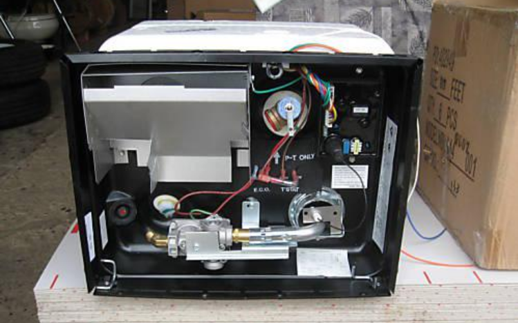
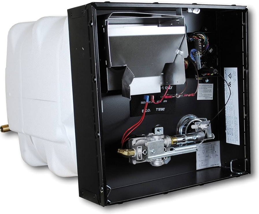
Atwood MPD 93755 Water Heater
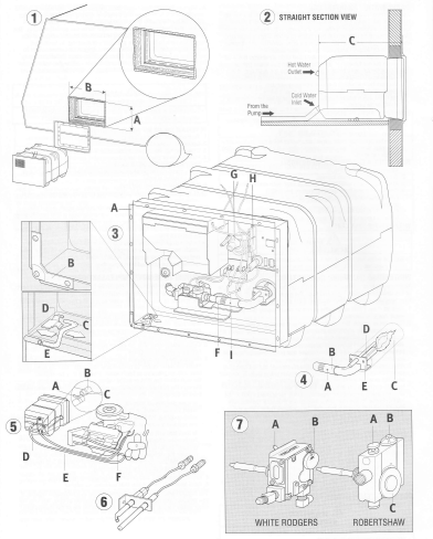
GENERAL INSTALLATION
This is a common installation for water heaters. There are other
approved methods such as Baggage Compartment (MPD 90093) and
Flush Mount (MPD 93948) installations. Consult with your Field
Auditor, Account Manager, or the Atwood Service Department if you
Have additional questions.
- Locate the water heater on the floor of the coach before erecting the side walls. The water heater tank must be permanently supported at the same level as the bottom of the sidewall cutout (by the floor or a raised floor), NC 2. Provide adequate clearance at the rear of the unit for the service of water connections.
- To install a water heater on carpeting, you must install the appliance on a metal or wood panel that extends at least three inches beyond the full width and depth of the appliance.
- If the appliance is installed where a connection or tank leakage will damage the adjacent area, install a drain pan (which can be drained to the outside of the coach) under the water heater.
- Connect both 1/2″ NPT water lines (or 2) hot water outlet female and a cold water inlet female, and a 3/8″ flared LP gas line to the water heater (or 9).
- a. Allow flexibility in water and gas lines so you can pull the unit forward through the wall one inch past the skin.
- b. Seal gas line entrance opening (RTC 9) by sliding grommet (9-B) onto 3/8″ tubing (9-D) before flaring tubing (9-E). Pull the gas line and grommet through the opening in the housing (9-A). Connect the flare-fitting
(9-C) and press the grommet into the opening. If the gas line tubing is already flared, cut a grommet on one side. Place a split grommet over the gas line and press it into the opening. - c. Always use pipe lubricant on threads when connecting hot and cold water couplings. A suitable plastic fitting is recommended.
- Erect side walls and cut an opening. See the chart and FrG 1. Frame with 2×2 lumber (or equivalent).
- Bend all flanges 90″ along scored lines (to 3-A).
- To prevent water leaks, caulk thoroughly around the opening, including bend slots. Butyl Tape (1-1/5’x1/8) may be substituted for caulking material.
- Push the unit against the caulking. Secure 4-corner brackets (to 3-B) to coach with No. 8 – 3i4″ round head screws (not furnished) or equivalent. Complete the installation by inserting the same type of #8 screws in the holes provided around the. Length of the water heater housing. Check all gas leaks. They must adhere to the plan, creating an air-tight seal.
- Attach the access doc.
- a. Snap hinge c r- =, 3-Ct into clip (rtc 3-D).
- b. Slide
CARE AND MAINTENANCE
SERVICE CALLS & QUESTIONS
Location and phone numbers of OTA,ified Service Centers can be found at our website http:/www.atwoodmca e.com or call 574-262-2655 to have a Service Center List mailed. Onto the hinge pin.
ELECTRONIC IGNITION MAINTENANCE
- The water heater comes factory-equipped with a fused circuit board, which will protect the circuit board from wiring shorts. If the fuse is activated, the air heater will not operate. Before replacing the fuse, check for a short external to the board. Once the shod is corrected, replace the 2 amp fuse with a mini ATO-style fuse. Do not install a fuse larger than 3 amps.
- If the fuse is good and the unit is inoperative, check for excessively high voltage to the unit (more than 14 volts).
- If the previous two steps did not solve the problem, check the
thermal cut-off (Ftc 3-l). The thermal cutoff is a device installed in the power supply line. This device will shut off electrical power and stop heater operation when activated. For example, if an obstruction within the flue tube should occur, as described in the Preventative Maintenance section, the burner flame/heat may contact the cutoff, resulting in a melting of the fuse element incorporated in the thermal cutoff. - To restore power and proper operation of the water heater, the obstruction must be removed and the thermal cutoff must be replaced.
WINTERIZING
To ensure the best performance of your water heater and add to the life of the tank, periodically drain and flush the water heater tank. Before long-term storage or freezing weather, drain and flush the tank.
- Turn off the main water supply (the pump or water supply (the pump or water hook-up source).
- Drain the Water Heater Tank by removing the drain plug- if the water flows sporadically or trickles instead of a steady stream of water, we recommend the following action: first open the Pressure Temperature Relief Valve to allow air into the tank and secondly, take a small gauge wire or coat hanger and poke through the drain opening to eliminate any obstructions.
- After draining the tank, because of the placement of the Drain Plug, approximately two quarts of water will remain in the tank. This water contains most of the harmful corrosive particles. To remove these harmful corrosive particles, flush the tank with either air or water. Whether using air or water pressure, it may be applied through the inlet or outlet on the rear of the tank or the Pressure Temperature Relief Valve. (If using the Pressure Temperature Relief Valve, the Support Flange must be removed.) The pressure will force out the
remaining water and the corrosive particles. If you use water pressure, pump fresh water into the tank with the assistance of the onboard pump or use external water for 90 seconds to allow the fresh water to agitate the stagnant water on the bottom of the tank and force deposits through the drain
opening. Continue repeating, adding water, and draining until the particles have been cleared from the water remaining in the tank. - Replace the Drain Plug and close the Pressure Temperature relief valve. The approximately two quarts of water remaining in the tank after draining will not cause damage to the tank should freezing occur.r
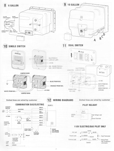
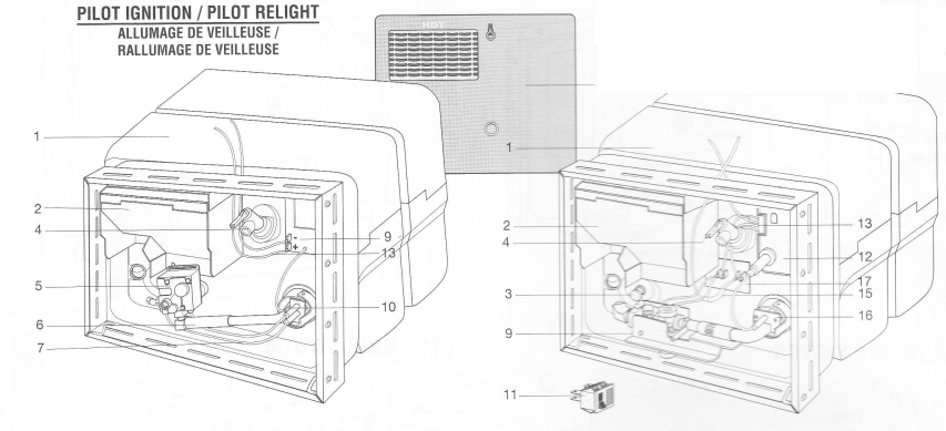
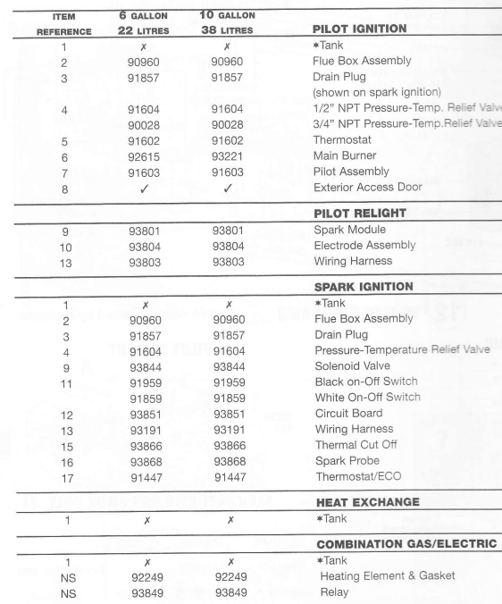
PART IDENTIFICATION
FOR MORE MANUALS BY ATWOOD, VISIT MANUALSLIBRARYY
Atwood MPD 93755 Water Heater-FAQs
How do I adjust the thermostat on my water heater?
Turn off power (electric/gas).
Locate the thermostat (usually behind an access panel).
Adjust the temperature (recommended: 120°F for safety, 140°F for higher demand).
Restore power and wait for water to heat.
How do I light the main burner on a gas water heater?
Turn off gas supply for 5 minutes.
Open the pilot light access panel.
Set gas knob to “Pilot” and hold while igniting.
Hold for 30 seconds, then turn to “On.”
Replace the panel.
How do I test a water heater element with a multimeter?
Turn off power and disconnect wires.
Set multimeter to ohms (Ω).
Touch probes to element terminals:
Good element: 10–16Ω.
Bad element: Infinite resistance (replace).
What’s the ideal water heater temperature setting?
120°F: Safe, energy-efficient, prevents scalding.
140°F: Better for dishwashers but increases mineral buildup.
How do I replace a water heater heating element?
Drain the tank (attach hose to drain valve).
Remove old element with a wrench.
Install new element with a gasket, then refill tank.
Does a gas water heater need electricity?
Pilot light models: No (works during power outages).
Electronic ignition models: Yes (requires power).
How do I check if my water heater is getting power?
Verify circuit breaker isn’t tripped.
Test outlet with a multimeter (should read 120V/240V).
How can I prevent water heater problems?
Flush sediment every 6 months.
Inspect anode rod yearly (replace if corroded).
Set temperature ≤120°F to reduce pressure buildup.
How long will hot water last during a power outage?
Electric heaters: 6–12 hours (insulated tank).
Gas heaters (pilot light): Unlimited (if no electric controls).

