
Yamaha YZ250 Motorcycle

GENERAL INFORMATION
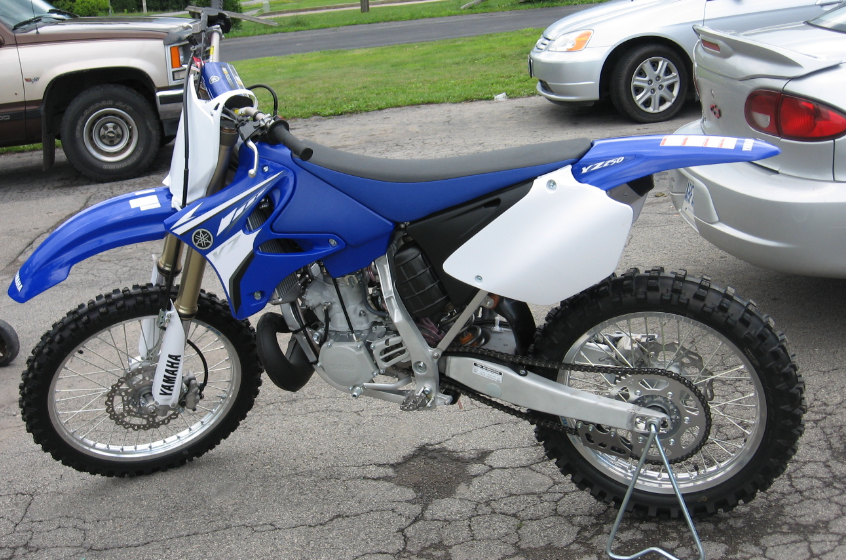
DESCRIPTION
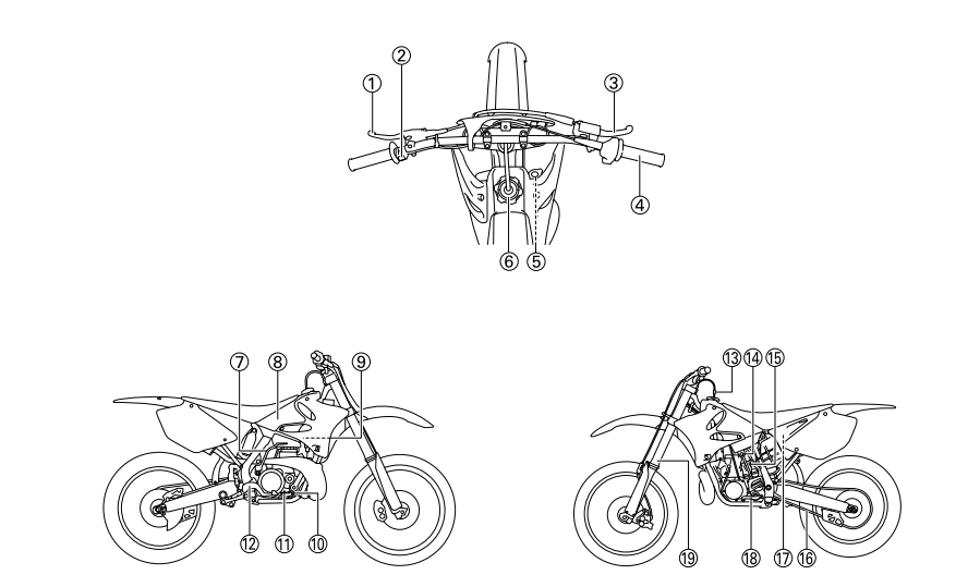
- Clutch lever
- Engine stop switch
- Front brake lever
- Throttle grip
- Radiator cap
- Fuel tank cap
- Kickstarter crank
- Fuel tank
- Radiator
- Coolant drain bolt
- Check bolt (Transmission oil level)
- Rear brake pedal
- Valve joint
- Fuel cock
- Starter knob
- Drive chain
- Air filter
- Shift pedal
- Front fork
Tip
- The machine you have purchased may differ slightly from those shown in the following.
- Designs and specifications are subject to change without notice
MACHINE IDENTIFICATION
VEHICLE IDENTIFICATION NUMBER
The vehicle identification number “1” is stamped on the right of the steering head pipe.

ENGINE SERIAL NUMBER
The engine serial number “1” is stamped into the elevated part of the right-side of the engine.

MODEL LABEL
The model label “1” is affixed to the frame under the rider’s seat. This information will be needed to order spare parts.

INCLUDED PARTS
DETACHABLE SIDESTAND
This sidestand “1” is used to support only the machine when standing or transporting it.
Warning
- Never apply additional force to the sidestand.
- Remove this sidestand before starting out.

VALVE JOINT
This valve joint “1” prevents fuel from flowing out and is installed to the fuel tank breather hose.
Notice: In this installation, make sure the arrow faces the fuel tank and also downward.

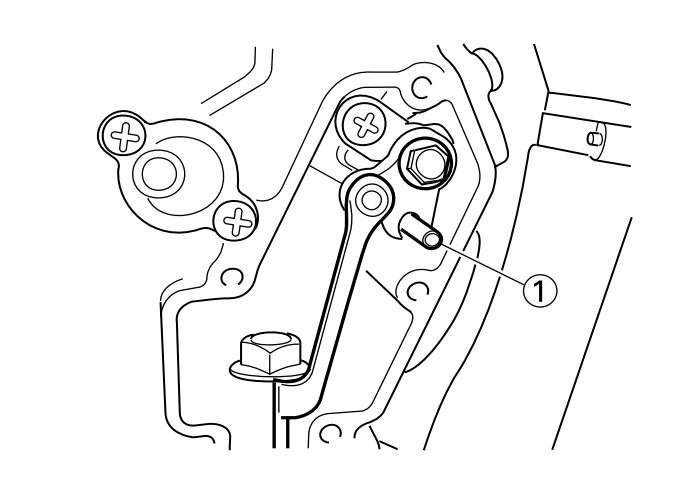
SET PIN
This set pin “1” is used to remove and install the push rod of the engine.
Notice: Be sure to use the set pin. If the set pin is not used, the power valve constituent parts will result in damage.
NIPPLE WRENCH
This nipple wrench “1” is used to tighten the spoke.

IMPORTANT INFORMATION
PREPARATION FOR REMOVAL AND DISASSEMBLY
- Remove all dirt, mud, dust, and foreign material before removal and disassembl
- When washing the machine with high pressured water, cover the parts follows. Silencer exhaust port Side cover air intake port Water pump housing hole at the bottom End of each hose


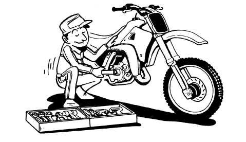
- Use proper tools and cleaning equipment. Refer to “SPECIAL TOOLS” section.

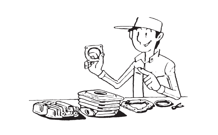
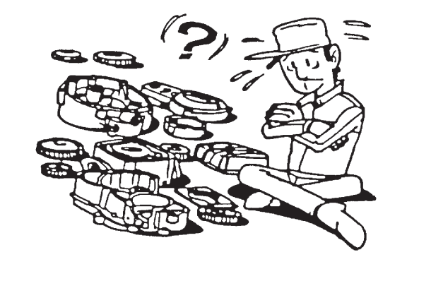
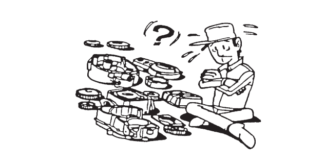
- When disassembling the machine, keep mated parts together. They include gears, cylinders, pistons, and other mated parts that have been “mated” through normal wear. Mated parts must be reused as an assembly or replaced.

- During the machine disassembly, clean all parts and place them in trays in the order of disassembly. This will speed up assembly time and help assure that all parts are correctly reinstalled.

- Keep away from fire.
- Use proper tools and cleaning equipment. Refer to “SPECIAL TOOLS” section.
ALL REPLACEMENT PARTS
- We recommend to use Yamaha genuine parts for all replacements. Use oil and/or grease recommended by Yamaha for assembly and adjustment.
GASKETS, OIL SEALS AND ORINGS
- All gaskets, oil seals, and O-rings should be replaced when an engine is overhauled. All gasket surfaces, oil seal lips, and O-rings must be cleaned.
- Properly oil all mating parts and bearings during reassembly. Apply grease to the oil seal lips.
LOCK WASHERS/PLATES AND COTTER PINS
- All lock washers/plates “1” and cotter pins must be replaced when they are removed. Lock tab(s) should be bent along the bolt or nut flat(s) after the bolt or nut has been properly tightened.

BEARINGS AND OIL SEALS
- Install the bearing(s) “1” and oil seal(s) “2” with their manufacturer’s marks or numbers facing outward. (In other words, the stamped letters must be on the side exposed to view.) When installing oil seal(s), apply a light
coating of lightweight lithium base grease to the seal lip(s). Oil the bearings liberally when installing.
NoticeDo not use compressed air to spin the bearings dry. This causes damage to the bearing surfaces.

CIRCLIPS
- All circlips should be inspected carefully before reassembly. Always replace piston pin clips after one use. Replace distorted circlips. When installing a circlip “1”, make sure that the sharp-edged corner “2” is positioned opposite to the thrust “3” it receives. See the sectional view.

CHECKING OF CONNECTION
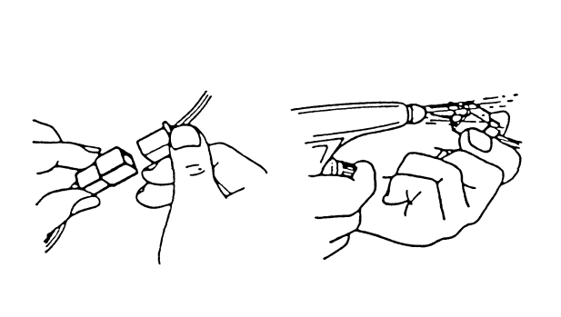
Dealing with stains, rust, moisture, etc. on the connector.
- Disconnect:
- Connector
- Dry each terminal with an air blower.

- Connect and disconnect the connector two or three times.
- Pull the lead to check that it will not come off.
- If the terminal comes off, bend up the pin “1” and reinsert the terminal into the connector.

- Connect:
- Connector
- Tip: The two connectors “click” together
- Check for continuity with a tester
Tip
- If there in no continuity, clean the terminals.
- Be sure to perform the steps 1 to 7 listed above when checking the wire harness.
- For a field remedy, use a contact revitalizer available on the market.
- Use the tester on the connector as shown.

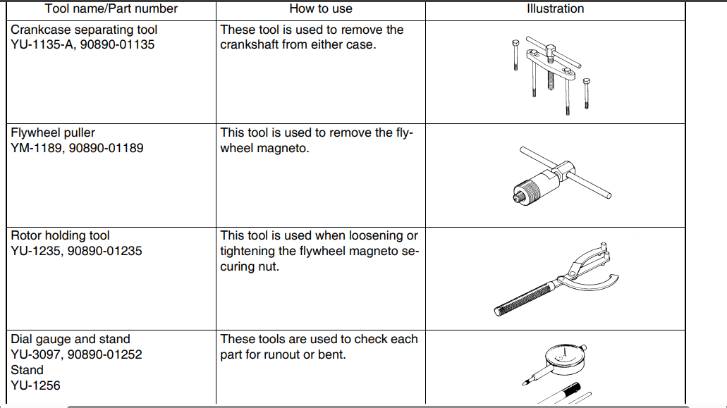
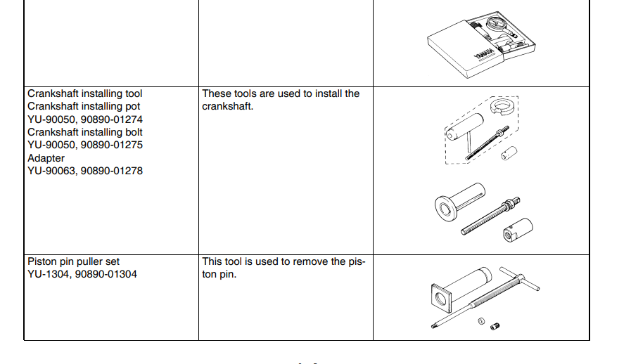
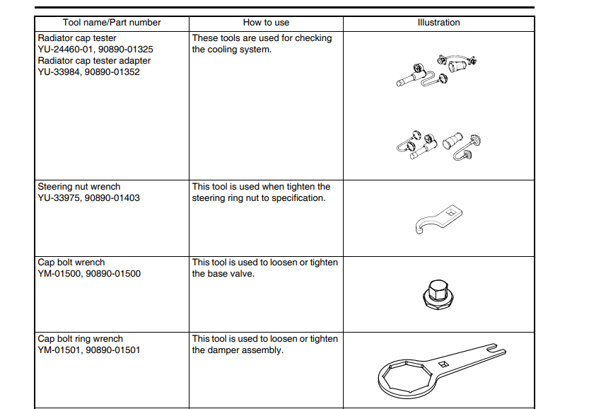
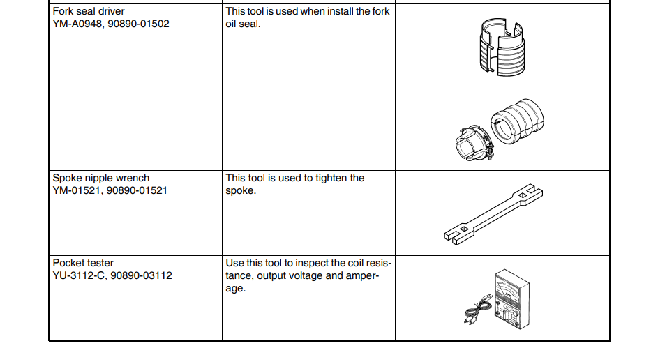
SPECIAL TOOLS
The proper special tools are necessary for complete and accurate tune-up and assembly. Using the correct special tool will help prevent damage caused by the use of improper tools or improvised techniques. The shape and part number used for the special tool differ by country, so two types are provided. Refer to the list provided to avoid errors when placing an order.
Tip
- For U.S.A. and Canada, use part number starting with “YM-“, “YU-” or “ACC-“.
- For others, use part number starting with “90890-“.

 CONTROL FUNCTIONS
ENGINE STOP SWITCH
The engine stop switch “1” is located on the left handlebar. Continue pushing the engine stop switch till the engine comes to a stop.

CLUTCH LEVER
The clutch lever “1” is located on the left handlebar; it disengages or engages the clutch. Pull the clutch lever to the handlebar to disengage the clutch, and release the lever to engage the clutch. The lever should be pulled rapidly and released slowly for smooth starts.

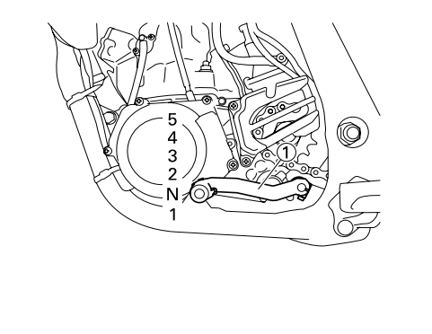
SHIFT PEDAL
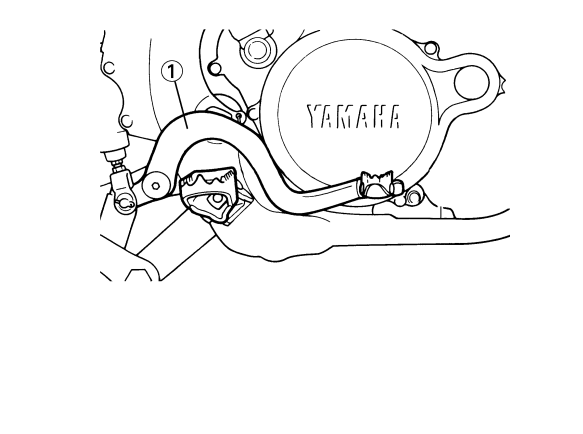
The gear ratios of the constant-mesh 5 speed transmission are ideally spaced. The gears can be shifted by using the shift pedal “1” on the left side of the engine.
KICKSTARTER CRANK
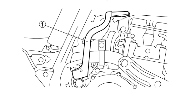
Rotate the kickstarter crank “1” away from the engine. Push the starter down lightly with your foot until the gears engage, then kick smoothly and forcefully to start the engine. This model has a primary kickstarter crank so the engine can be started in any gear if the clutch is disengaged. In normal practices, however, shift to neutral before starting
THROTTLE GRIP
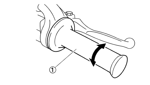
The throttle grip “1” is located on the right handlebar; it accelerates or decelerates the engine. For acceleration, turn the grip toward you; for deceleration, turn it away from you.
FRONT BRAKE LEVER
The front brake lever “1” is located on the right handlebar. Pull it toward the handlebar to activate the front brake.

REAR BRAKE PEDAL
The rear brake pedal “1” is located on the right side of the machine. Press down on the brake pedal to activate the rear brake.
FUEL COCK
The fuel cock supplies fuel from the tank to carburetor and also filters the fuel. The fuel cock has the two positions:
OFF:
With the lever in this position, fuel will not flow. Always return the lever to this position when the engine is not running.
ON:
With the lever in this position, fuel flows to the carburetor. Normal riding is done with the lever in this position.

STARTER KNOB (CHOKE)
When cold, the engine requires a richer air-fuel mixture for starting. A separate starter circuit, which is controlled by the starter knob “1”, supplies this mixture. Pull the starter knob out to open the circuit for starting. When the engine has warmed up, push it in to close the circuit

STARTING AND BREAK-IN FUEL
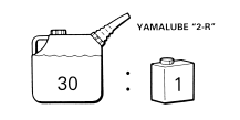
Mix oil with the gas at the ratio specified below. Always use fresh, namebrand gasoline, and mix the oil and gas the day of the race. Do not use premix that is more than a few hours old.
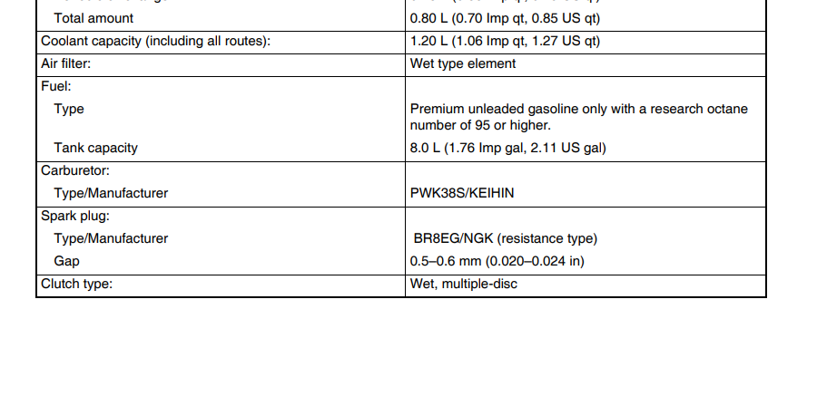
Recommended fuel: Premium unleaded gasoline only with a research octane number of 95 or higher.
Tip: If knocking or pinging occurs, use a different brand of gasoline or higher octane grade.
STARTING AND BREAK-IN
Notice:Never mix two types of oil in the same batch; clotting of the oil could result. If you wish to change oil types, be sure to drain the fuel tank and the carburetor float bowl of old premix prior to filling with the new type.
- Fuel tank capacity: 8.0 L (1.76 Imp gal, 2.11 US gal)
- Mixing oil: Recommended oil: Yamalube “2-R” (Yamalube racing 2- cycle oil)
- Mixing ratio: 30:1
If unavailable, use an equivalent type of oil.
HANDLING NOTE
Notice: Before starting the machine, perform the checks in the pre-operation check list.
Warning: Never start or run the engine in a closed area. The exhaust fumes are poisonous; they can cause loss of consciousness and death in a very short time. Always operate the machine in a well-ventilated area.
AIR FILTER MAINTENANCE
According to “CLEANING THE AIR FILTER ELEMENT” section in the CHAPTER 3, apply the foam-air-filter oil or its equivalent to the element. (Excess oil in the element may adversely affect engine starting.)
STARTING A COLD ENGINE
- Shift the transmission into neutral.
- Turn the fuel cock to “ON” and full open the starter knob (CHOKE).
- With the throttle completely closed start the engine by kicking the kick starter forcefully with firm stroke.
- Run the engine at idle or slightly higher until it warms up: this usually takes about one or two minutes.
- The engine is warmed up when it responds normally to the throttle with the starter knob (CHOKE) turned off
Notice: Do not warm up the engine for extended periods of time.
STARTING A WARM ENGINE
Do not operate the starter knob (CHOKE). Open the throttle slightly and start the engine by kicking the kick starter forcefully with firm stroke
Notice: Observe the following break-in procedures during initial operation to ensure optimum performance and avoid engine damage.
BREAK-IN PROCEDURES
- Before starting the engine, fill the fuel tank with a break-in oil-fuel mixture as follows.
- Mixing oil: Yamalube “2-R”
- Mixing ratio: 15:1
- Perform the pre-operation checks on the machine.
- Start and warm up the engine. Check the idle speed, and check the operation of the controls and the “ENGINE STOP” button.
- Operate the machine in the lower gears at moderate throttle openings for five to eight minutes. Stop and check the spark plug condition; it will show a rich condition during break-in.
- Allow the engine to cool. Restart the engine and operate the machine as in the step above for five minutes. Then, very briefly shift to the higher gears and check fullthrottle response. Stop and check the spark plug.
- After again allowing the engine to cool, restart and run the machine for five more minutes. Full throttle and the higher gears may be used, but sustained full-throttle operation should be avoided. Check the spark plug condition.
- Allow the engine to cool, remove the top end, and inspect the piston and cylinder. Remove any high spots on the piston with #600 grit wet sandpaper. Clean all components and carefully reassemble the top end.
- Drain the break-in oil-fuel mixture from the fuel tank and refill with the specified mix.
- Restart the engine and check the operation of the machine throughout its entire operating range. Stop and check the spark plug condition. Restart the machine and operate it for about 10 to 15 more minutes. The machine will now be ready to race.
Notice:
- After the break-in or before each race, you must check the entire machine for loose fittings and fasteners as per “TORQUECHECK POINTS”. Tighten all such fasteners as required.
- When any of the following parts have been replaced, they must be broken in.
CYLINDER AND CRANKSHAFT: About one hour of break-in operation is necessary. PISTON, RING AND GEARS: These parts require about 30 minutes of break-in operation at half-throttle or less. Observe the condition of the engine carefully during operation
CLEANING AND STORAGE
CLEANING
Frequent cleaning of your machine will enhance its appearance, maintain good overall performance, and extend the life of many components.
- Before washing the machine, block off the end of the exhaust pipe to prevent water from entering. A plastic bag secured with a rubber band may be used for this purpose.
- If the engine is excessively greasy, apply some degreaser to it with a paint brush. Do not apply degreaser to the chain, sprockets, or wheel axles.
- Rinse the dirt and degreaser off with a garden hose; use only enough pressure to do the job.
Notice: Excessive hose pressure may cause water seepage and contamination of wheel bearings, front forks, brakes and transmission seals. Many expensive repair bills have resulted from improper high pressure detergent applications such as those available in coin-operated car washers.
- After the majority of the dirt has been hosed off, wash all surfaces with warm water and a mild detergent. Use an old toothbrush to clean hard-to-reach places.
- Rinse the machine off immediately with clean water, and dry all surfaces with a soft towel or cloth.
- Immediately after washing, remove excess water from the chain with a paper towel and lubricate the chain to prevent rust.
- Clean the seat with a vinyl upholstery cleaner to keep the cover pliable and glossy.
- Automotive wax may be applied to all painted or chromed surfaces. Avoid combination cleaners and waxes, as they may contain abrasives.
- After completing the above, start the engine and allow it to idle for several minutes.
STORAGE
If your machine is to be stored for 60 days or more, some preventive measures must be taken to avoid deterioration. After cleaning the machine thoroughly, prepare it for storage as follows:
- Drain the fuel tank, fuel lines, and the carburetor float bowl.
- Remove the spark plug, pour a tablespoon of SAE 10W-30 motor oil in the spark plug hole, and reinstall the plug. With the engine stop switch pushed in, kick the engine over several times to coat the cylinder walls with oil.
- Remove the drive chain, clean it thoroughly with solvent, and lubricate it. Reinstall the chain or store it in a plastic bag tied to the frame.
- Lubricate all control cables.
- Block the frame up to raise the wheels off the ground.
- Tie a plastic bag over the exhaust pipe outlet to prevent moisture from entering.
- If the machine is to be stored in a humid or salt-air environment, coat all exposed metal surfaces with a film of light oil. Do not apply oil to rubber parts or the seat cover.
Tip: Make any necessary repairs before the machine is stored
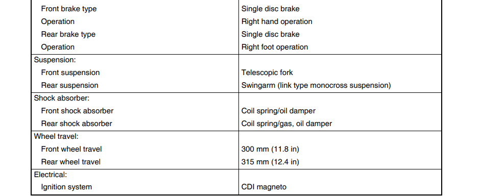
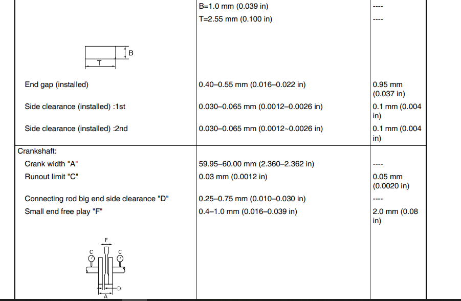
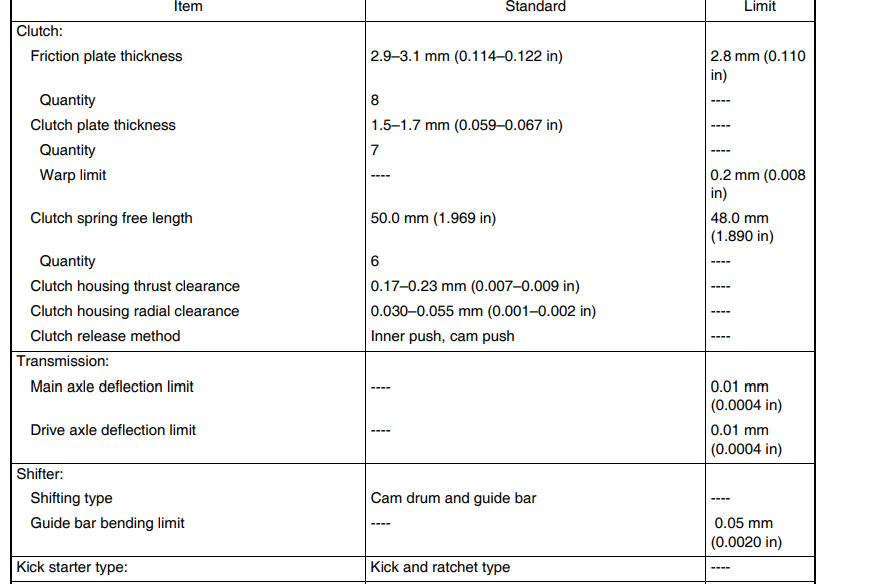
GENERAL SPECIFICATIONS





For more manuals by Yamaha, visit ManualsLibraryy
How many gears does the Yamaha YZ250 have?
The YZ250 features a 5-speed constant-mesh transmission with a manual clutch. The gear pattern is standard: 1-N-2-3-4-5.
What is the engine specification and power output?
The YZ250 is powered by a 249cc, liquid-cooled, two-stroke single-cylinder engine. It produces approximately 47 horsepower and 30.6 lb-ft of torque, with a redline around 9,000 RPM.
What is the top speed of a YZ250?
A YZ250 can reach a top speed of approximately 85 mph (137 km/h), depending on rider weight, terrain, and gearing.
How long does a YZ250 engine last before a rebuild?
Engine life depends entirely on riding style:
Aggressive/Racing Use: A top-end rebuild is recommended every 25-50 hours.
Trail/Recreational Riding: A top-end can last 80-115 hours.
What is the fuel/oil mixing ratio for a YZ250?
Yamaha recommends a fuel-to-oil ratio between 30:1 and 40:1. Always use high-quality 2-stroke oil and premium unleaded gasoline. Re-jetting the carburetor may be necessary for optimal performance with your chosen ratio.
What is the difference between the YZ250 and the YZ250X?
The YZ250 is tuned for motocross track performance with a focus on peak horsepower. The YZ250X is the off-road/enduro version, featuring a wider-ratio 5-speed transmission, revised power valve and ignition timing for smoother low-end power, an 18-inch rear wheel, and a kickstand.
What is a quickshifter? Does the YZ250 have one?
A quickshifter allows for clutchless upshifts by momentarily cutting ignition when an upward force is detected on the shift lever. The standard YZ250 does not come with a quickshifter from the factory, but aftermarket options are available.
What is a slipper clutch? Does the YZ250 have one?
A slipper clutch helps prevent rear wheel hop and lock-up during aggressive downshifting. The standard YZ250 does not have a slipper clutch, but the Yamaha-branded A&S (Assist & Slipper) clutch is a popular aftermarket upgrade.


 CONTROL FUNCTIONS