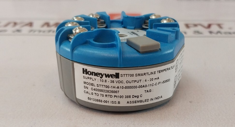
Honeywell STT700 SmartLine Temperature Transmitter
Installation
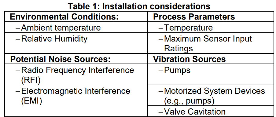
For start-up, operation (including configuration), maintenance, and calibration, refer to the STT700 Transmitter User’s manual, #34-TT-25-17. Evaluate the site selected for the Transmitter installation with respect to the process system design specifications and Honeywell’s published performance characteristics for your particular model. Conditions to be considered include:
In preparation for post-installation processes, refer to the MC Toolkit User Manual, Document # #34-ST-25-50 (MCT404), for battery conditioning and device operation and maintenance information.
DEVICE CONFIGURATION
This transmitter comes with a standard factory configuration. Consult the nameplate for basic information. Reconfiguration for your particular application can be accomplished by following the instructions in the Transmitter User’s manual. This can be found by following the website URL or QR code on page 1 of this document.
Features and Options
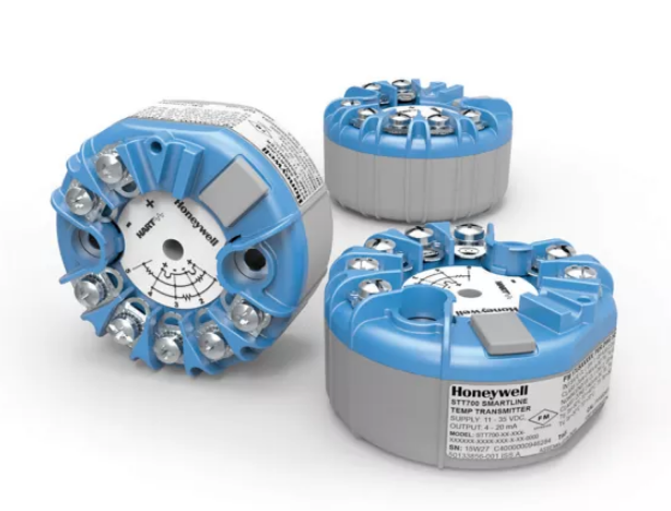
As shown in Figure 1, the STT700 is packaged in a single module. The elements in this module are connected to the process sensors, measure the process variables, respond to setup commands, and execute the software and protocol for the different temperature measurement types.
Figure 1 – STT700 Temperature Transmitter (HART left, DE right)
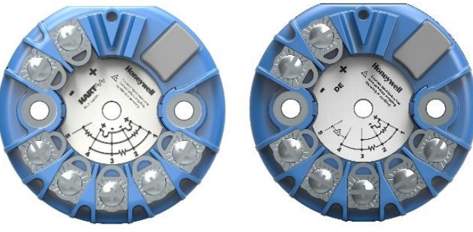
Figure 2 – STT700 Temperature Transmitter with display module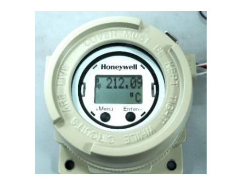
The transmitter measures process temperature and outputs a signal proportional to the measured process variable (PV). Available output communication protocols include 4 to 20mA, Honeywell Digitally Enhanced (DE), and HART protocols.
Mounting the Transmitter
DIN Rail Mounting
If the STT700 is to be installed on DIN Rail, then the main considerations are electrical connections and mechanical fixing. Electrical connections are identical to the bench test instructions except that thermocouple wire is likely to be used with thermocouples. Mechanical fixing of the module is by means of the snap-in DIN Rail Clips, which are screwed to the bottom lugs of the module.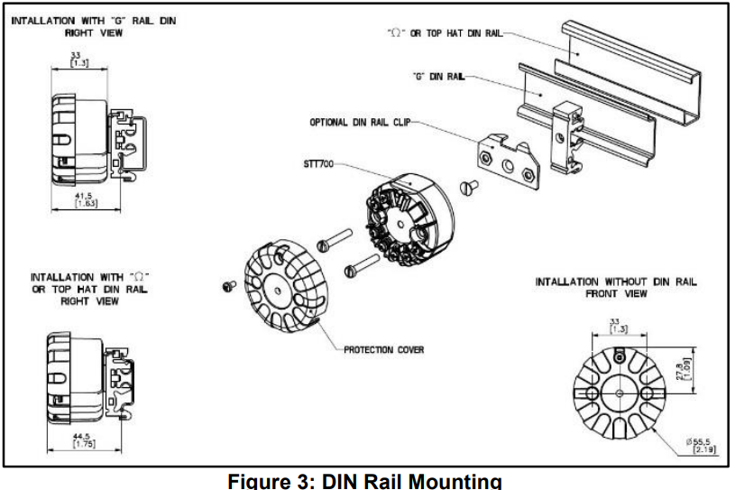
The DIN Rail needs to be connected to Earth Ground. Refer to STT700 SmartLine transmitter user’s manual, #34-TT-25-17.
Uninstalling/Installing the EU Meter from Housing
EU Meter:
- Remove the EU METER from the mounting bracket.
- Unfasten the 2 mounting screws.
- Remove the bracket.
- To put the EU meter back, follow the above sequence in the reverse order.
Uninstalling/Installing Standard Display from Housing
Standard Display:
- Loosen the bracket screws
- Move the display in a clockwise direction till the STT700 connections are exposed
- Slide and remove the cable joint from the display panel bracket
- Disconnect the cables from the display panel and STT700 transmitter
- Remove the Standard Display from the bracket.
- To reinstall the Standard Display, reverse the above sequence.
Housing Cover and O Ring:
- Review O-ring condition & replace if damaged. A new O-ring can be ordered from the spare parts list.
- Apply O-ring lubricant to the end cap O-ring. Relax O-ring twists, if any. Assemble the housing cover with sufficient torque for securing against IP.
Mounting Module in Housing
The STT700 module can be installed in a variety of housings suitable for direct head mounting, 2” (50mm) pipe mounting, or wall mounting.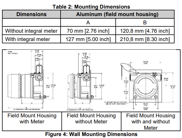
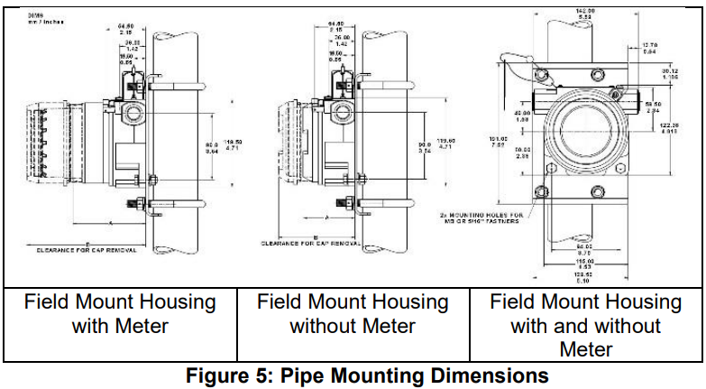
Spring Loading
Spring loading is available worldwide with direct head mounting. In North America, the spring loading is typically included in the sensor/thermowell assembly and is available with all housings. For non-North American spring loading as shown in Figure 6, simply include the springs under the 33 mm pitch mounting screws, pass the screws through the module and sensor mounting plate, and snap in the retaining circlip to the screws to hold the assembly together. Guide the sensor assembly through the housing sensor entry and screw down the 33 mm screws until the limit is reached as the sensor presses against the bottom of the thermowell.
For wall or 2” pipe mounting, the temperature sensor can be remote from the STT700 field mount housing or integral to the housing. For remote installations, the sensor wiring should be run in shielded, twisted pair wiring and connected via one of the housing wiring entries. For explosionproof/flameproof installations, ensure that the cable entries are fitted with flameproof adaptors and that the wiring grade complies with local standards. For more details on wiring and dimensions for the Aluminum Direct head and the Cast iron Direct head, refer to STT700 SmartLine transmitter user’s manual, #34-TT-25-17.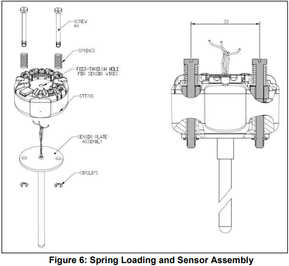
Wiring Connections and Power Up
Summary
The transmitter is designed to operate in a two-wire power/current loop with loop resistance and power supply voltage within the HART and DE operating ranges shown in Figure 7.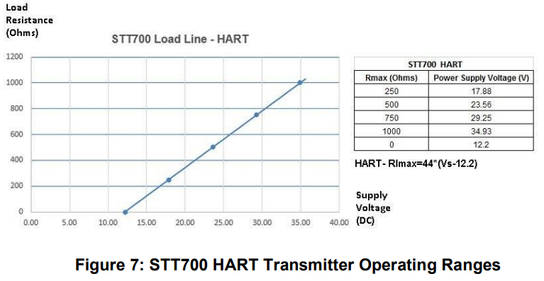
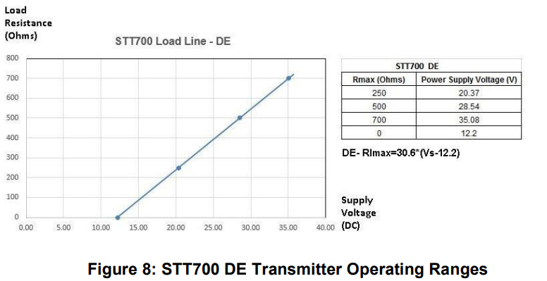
Loop wiring is connected to the transmitter by simply attaching the positive (+) and negative (–) loop wires to the positive (+) and negative (–) terminals on the transmitter terminal block in the electronics housing shown in Figure 9. Route the wires through the pre-molded channels on the connector cap. Connect the loop power wiring shield to earth ground only at the power supply end. Note that loop power for this transmitter is not polarity-sensitive.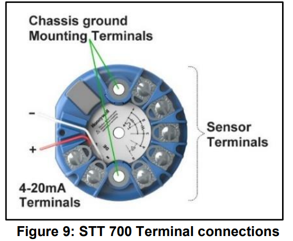
This transmitter uses the two mounting screws to connect it to the earth ground. Grounding the transmitter for proper operation is required, as doing so tends to minimize the possible effects of noise on the output signal and affords protection against lightning and static discharge. An optional lightning protection module is available for use in areas that are highly susceptible to lightning strikes. As noted above, the loop power wiring shield should only be connected to earth ground at the power supply end.
For HART and DE, the transmitter is designed to operate in a two-wire power/current loop with loop resistance and power supply voltage within the operating range; see Figure 9. With an optional remote meter, the voltage drop for this must be added to the basic power supply voltage requirements to determine the required transmitter voltage (VXMTR) and maximum loop resistance (RLOOP MAX). Additional consideration is required when selecting intrinsic safety barriers to ensure that they will supply at least the minimum transmitter voltage (VXMTR MIN), including the required 250 ohms of resistance (typically within the barriers) needed for digital communications.
Wiring Variations
The above procedures are used to connect power to a transmitter. For loop wiring and external wiring, detailed drawings are provided for transmitter installation in non-intrinsically safe areas and for intrinsically safe loops in hazardous area locations. This procedure shows the steps for connecting power to the transmitter. The screw terminals are suitable for wiring up to (16AWG)
- Shielded, twisted-pair cable such as Belden 9318 or equivalent must be used for all signal/power wiring. Note: If solid core wire is used, strip insulation 1/4 in (6 mm). Once inserted under the square washer, the stripped portion should be contained under the square washer. If a multi-stranded wire is used, a ferrule is to be used, and the stripped wire should be in the insulated portion of the ferrule. The ferrule can also be used on the solid core wire.
- The cable shield must be connected at only one end of the cable. Connect it to the power supply side and leave the shield insulated at the transmitter side. After wiring the Transmitter as outlined in the next sections, torque the screws to 1.1 Nm (10 lb-in).
Grounding and Lightning Protection
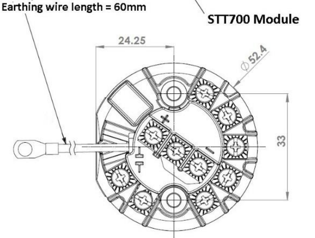
Connect a wire from the mounting screws to the earth ground to make the protection effective. Use a size 8 AWG (8.37mm2) bare or green-covered wire for this connection. For ungrounded thermocouple, mV, RTD, or ohm inputs, connect the input wiring shield(s) to the same earth ground connection. For grounded thermocouple inputs, connect the internal ground connection shown in Figure 9 to the same earth ground as used by the thermocouple. As noted above, the loop power wiring shield should only be connected to earth ground at the power supply end. For DE, the burnout direction needs to be selected in the hardware, and this will be detected at power-on time.
Input Sensor Wiring
Connect the input sensors as shown in Figure 10 below: RTD, Thermocouple, mV, Ohm, and Millivolt connections.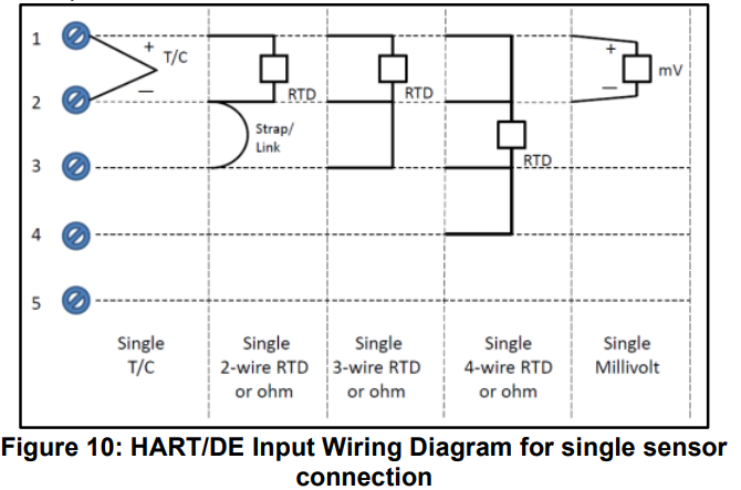
The single sensor connections can also be used on a dual-input transmitter when a second input is not required. In this case, it is recommended that the second input be configured to none in software. In case of RTD type being configured to 4-wire, this is automatically done.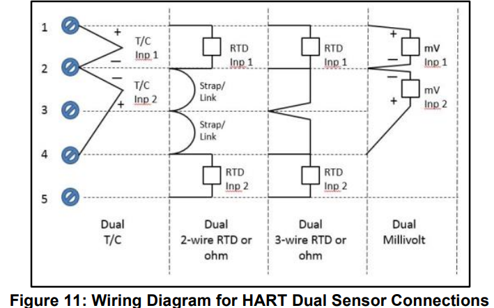
LIGHTNING PROTECTOR
This device is designed to give the SmartLine temperature transmitter maximum protection against surges such as those generated by lightning strikes. The lightning protector mounts right on the top of the STT700 terminal block, providing easy field wiring and also protection for the EU meter if used. For more details, refer to STT700 SmartLine temperature transmitter user’s manual, #34-TT-25-17.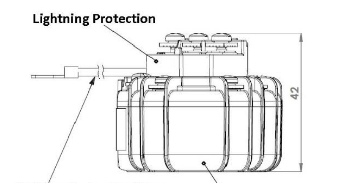
Installation
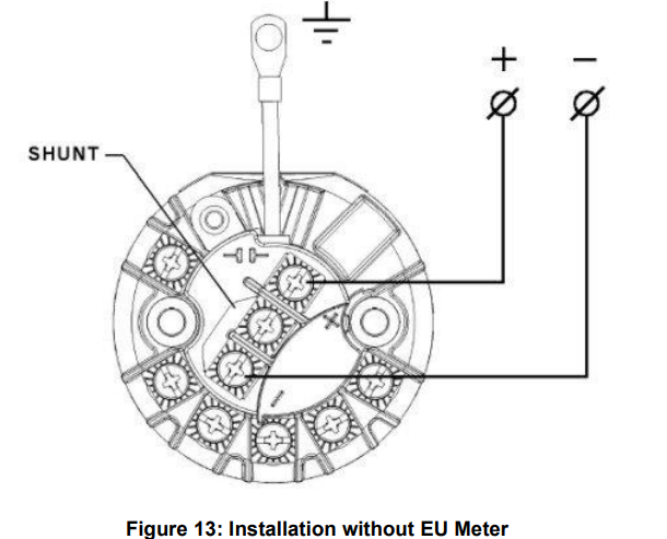
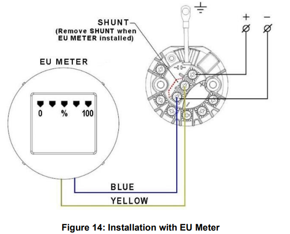
- If an EU meter is used, remove the shunt on the Lightning Protector. In all other cases, the shunt must be present.
- If Standard Display is used, no need to remove the shunt.
- Remove the cover/cap of the housing (if applicable). The device fits on the top of the transmitter module terminal block, and the transmitter output screws (+ and -) fix the device mechanically.
- If Standard Display is used, remove the cover of the housing and connect the display cable to the 8-Pin connector provided on the transmitter.
- Attach the grounding wire to the ground screw in the housing. Connect a wire from the transmitter enclosure to the local earth ground. Use size 14 AWG or 2.0mm2 bare or green-covered wire.
- If an EU meter is used, wire according to Figure 14.
- If Standard Display is used, wire according to Figure 15.
- Connect the 4 – 20mA loop to the + and – terminal screws of the surge protection and close the cap of the housing.


For start-up, operation (including configuration), maintenance, and calibration, refer to the STT700 Transmitter User’s manual, #34-TT-25-17.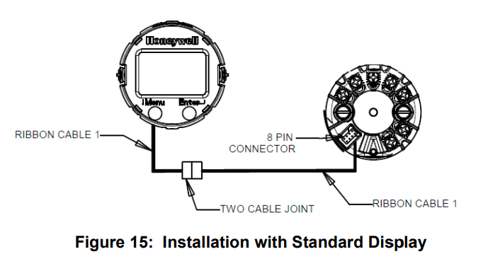
Appendix A. PRODUCT CERTIFICATIONS
A1. Safety Instrumented Systems (SIS) Installations
For Safety Certified Installations, please refer to STT700 Safety Manual #34-TT-25-05 for installation procedure and system requirements.
A2. China RoHS
China RoHS compliance information is located here: (Pending) https://www.honeywellprocess.com/library/support/Public/Documents/50136434.pdf
A.6 Conditions of Use” for Ex Equipment”, Hazardous Location Equipment, or “Schedule of Limitations”:
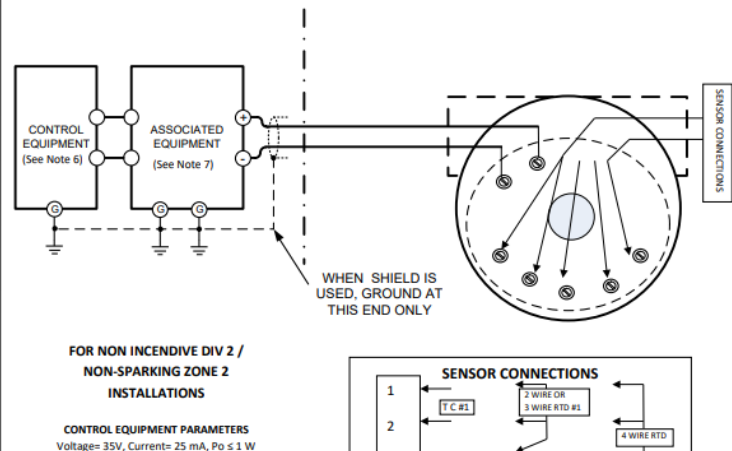
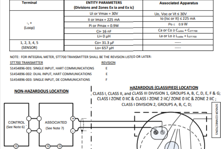
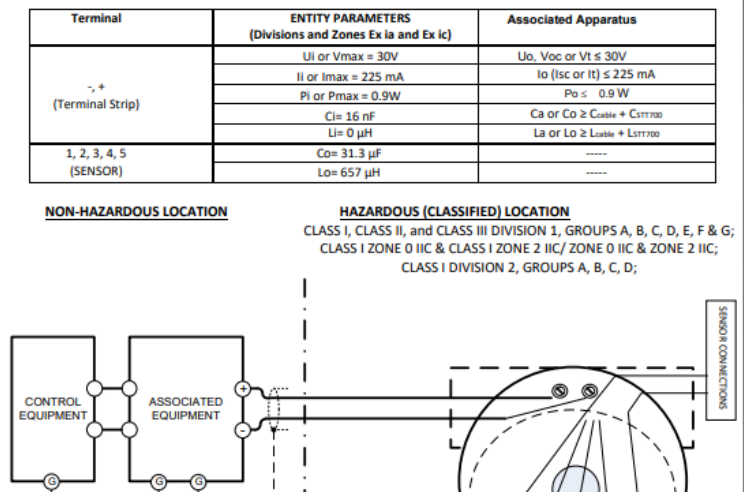
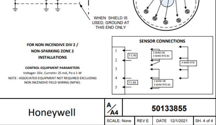
The installer shall provide transient over-voltage protection external to the equipment such that the voltage at the supply terminal of the equipment does not exceed 140% of the voltage rating of the equipment. Intrinsically Safe: Must be installed per drawing 50133855 Division 2: This equipment is suitable for use in a Class I, Division 2, Groups A, B, C, D; T4 or Non-Hazardous Locations Only.
Transmitter only Selection:
- For US Installations: The transmitter is to be installed within an enclosure with a minimum degree of protection of IP54 in accordance with ANSI/ISA 60079-15 and in a tool-secured enclosure which meets the requirements of ANSI/ISA 60079-0 and ANSI/ISA 60079-15 and the ultimate application.
- For ATEX or IECEx: The transmitter is to be installed within an enclosure with a minimum degree of protection of IP54 in accordance with EN/ IEC 60079-7 and in a tool-secured enclosure which meets the requirements of EN/ IEC 60079-0 and EN/ IEC 60079-15 and the ultimate application.
Transmitter in Enclosure Selections:
- Consult the manufacturer for dimensional information on the flameproof joints for repair.
- The painted surface of the Aluminum Enclosure may store electrostatic charge and become a source of ignition in applications with a low relative humidity of less than approximately 30% relative humidity, where the painted surface is relatively free of surface contamination such as dirt, dust, or oil. Cleaning of the painted surface should only be done with a damp cloth. The enclosure is manufactured from low copper aluminum alloy. In rare cases, ignition sources due to impact and friction sparks could occur. This shall be considered during Installation, particularly if equipment is installed in a Zone 0 location.
- If a charge-generating mechanism is present, the exposed metallic part on the enclosure is capable of storing a level of electrostatic charge that could become incendiary for IIC gases. Therefore, the user/ installer shall implement precautions to prevent the buildup of electrostatic charge, e.g., earthing the metallic part. This is particularly important if equipment is installed in a Zone 0 location.
STT700 HART/DE WITHOUT LP, WITHOUT INTEGRAL METER OR EU METER (WITHOUT ENCLOSURE)
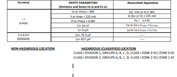

STT700 HART/DE WITH OR WITHOUT LP, WITH OR WITHOUT INTEGRAL METER, WITHOUT EU METER (WITH ENCLOSURE)
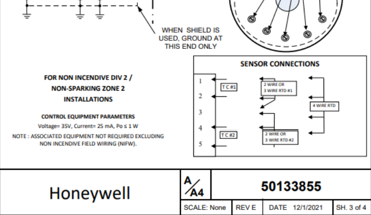
STT700 HART/DE WITH OR WITHOUT LP, WITHOUT INTEGRAL METER, WITH EU METER (WITH ENCLOSURE)
Sales and Service
For application assistance, current specifications, pricing, or the name of the nearest Authorized Distributor, contact one of the offices below.
- ASIA PACIFIC (TAC) [email protected]
- Australia Honeywell Limited, Phone: +(61) 7-3846 1255, Toll Free 1300-36-39-36, Toll Free Fax: 1300-36-04-70
- China – PRC – Shanghai, Honeywell China Inc. Phone: (86-21) 5257-4568, Fax: (86-21) 6237-2826
- Singapore, Honeywell Pte Ltd. Phone: +(65) 6580 3278. Fax: +(65) 6445-3033
- South Korea, Honeywell Korea Co Ltd. Phone (822)799 6114. Fax:+(822) 792 9015
- EMEA, Phone: + 80012026455 or +44 (0)1202645583. Email: (Sales) [email protected] or (TAC) [email protected]
- Web: Knowledge Base search engine http://bit.ly/2N5Vldi
- AMERICAS, Honeywell Process Solutions, Phone: (TAC) 1-800-423-9883 or 215/641-3610. (Sales) 1-800-343-0228. Email: (Sales) [email protected] or (TAC) [email protected]
- Web: Knowledge Base search engine http://bit.ly/2N5Vldi
WARRANTY/REMEDY
Honeywell warrants goods of its manufacture as being free of defective materials and faulty workmanship. Contact your local sales office for warranty information. If warranted goods are returned to Honeywell during the period of coverage, Honeywell will repair or replace without charge those items it finds defective. The foregoing is Buyer’s sole remedy and is in lieu of all other warranties, expressed or implied, including those of merchantability and fitness for a particular purpose.
Specifications may change without notice. The information we supply is believed to be accurate and reliable as of this printing. However, we assume no responsibility for its use. While we provide application assistance personally, through our literature and the Honeywell website, it is up to the customer to determine the suitability of the product in the application.
For more information
To learn more about SmartLine transmitters, visit https://process.honeywell.com/ or contact your Honeywell Account Manager
For More Manuals By Honeywell, Visit ManualsLibraryy.
Honeywell STT700 SmartLine Temperature Transmitter-FAQs
What does CFR Part 11 cover?
21 CFR Part 11 sets FDA regulations for the use of electronic records and electronic signatures, ensuring their authenticity, integrity, and security.
What is the role of electronic signatures in pharma?
They are used to approve SOPs, batch records, validation reports, and critical documents, ensuring compliance and traceability.
What are the benefits of Part 11 compliance?
It improves data integrity, security, and efficiency by allowing businesses to digitize record-keeping and approval processes.
What challenges do organizations face with Part 11 compliance?
Common gaps include weak access controls, incomplete audit trails, system validation issues, and improper user management.
What types of electronic signatures exist?
The three main types are Simple Electronic Signatures (SES), Advanced Electronic Signatures (AES), and Qualified Electronic Signatures (QES).
What are the four key requirements for a valid e-signature?
Intent to sign, consent to use e-signatures, proper authentication, and secure record retention.
What documents cannot be signed electronically?
Generally excluded are wills, property deeds, marriage, birth, and death certificates, or any documents legally requiring wet signatures.
What documents can e-signatures be used for?
They are valid for contracts, authorizations, service agreements, and most business or compliance records.

