
Frontier 20 Series Rotary Cutter

GENERAL DESCRIPTION
Your 20 Series Frontier Rotary Cutter has been carefully designed for cutting grass and small brush. This manual is provided to give you the necessary operation and maintenance instructions for keeping your rotary cutter in excellent operating condition. Please read this manual thoroughly. Understand the purpose of the controls and how to use them. Observe all safety precautions on the machine and as noted throughout this
manual. If any assistance or additional information is needed, contact your authorized Frontier dealer. Each cutter has free-swinging blades, which reduce the shock on impact when a stationary object is hit. A shear bolt through the input shaft or slip clutch-equipped driveline protects the gearbox and driveline from damage.
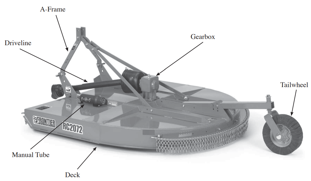
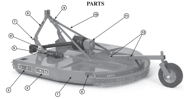
Major components
TECHNICAL DESCRIPTION
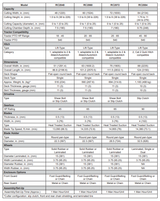
PREPARATION
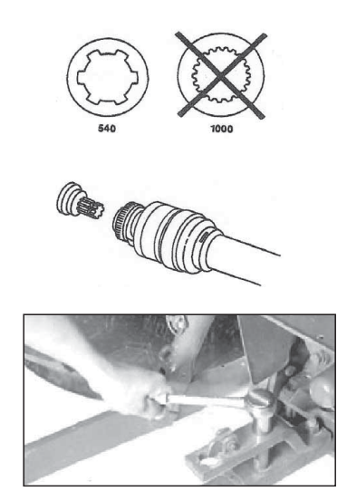
- Selecting Tractor PTO Speed
IMPORTANT: Never operate a cutter equipped for a 540 rpm PTO drive with a tractor equipped for 1000 rpm PTO. Always run the tractor at the rated PTO speed. Overspeed will cause damage to the drive system. Refer to your tractor Operator’s Manual to change the PTO stub shaft, if necessary.
- Positioning Drawbar
IMPORTANT: To prevent damage to the driveline, remove, shorten, or place the drawbar to one side. If equipped with a clevis, remove it.
Preparing the Cutter
Perform the following procedures before operating the cutter:
Gearbox
- Check oil level. (See Lubrication and Maintenance section.)
- Check hardware torque. (See Lubrication and Maintenance section.)
- Remove any material wound on gearbox shafts.
- Check oil seals for leaks
Blades and Blade Holder
- Inspect blades for wear or damage. (See CHECKING BLADE WEAR in the Service section.)
- Check blade hardware torque. (See Lubrication and Maintenance section.)
- Check the blade holder hardware torque.
Hitch Pins
- Check the torque on the hitch pin lock nut.
- Ensure all bolts on the cutter are fastened securely.
Lubricating the Cutter
- Lubricate the cutter and driveline. (See Lubrication and Maintenance section.)
Installing Hitch Pin Bushings for Category 1 Quick Coupler Hitch
NOTE: Install bushings on both hitch pins. Right-hand side shown. Use the Frontier category 1 quick coupler bushing kit WS862500 or the John Deere quick coupler bushing kit BW15056.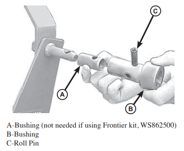
- If using the John Deere bushing kit BW15056 on RC2048, RC2060, or RC2072, install bushing (A) over the hitch pin with a cross hole as shown.
- Install bushing (B) as shown.
- Align holes in bushings with the hole in the hitch pin and install the roll pin (C).
- For RC2084, use the John Deere bushing kit BW15056. Bushing A is not required.
Using Category 2, 3-Point Hitch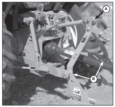
Special adapter bushings are available from your John Deere dealer to accommodate tractors with a category 2, 3-point hitch. Install bushings on the cutter hitch pins and the tractor center link connection.
- A – Center Link Connection
- B – Hitch Pins
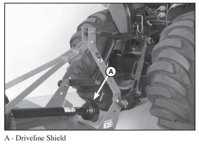
Checking Driveline Shields
Check driveline shields by making sure they rotate freely. Lubricate or repair if necessary
ATTACHING
Attaching the Cutter to the Tractor with a Quick Coupler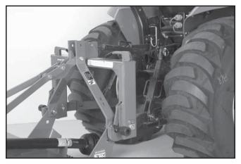
- Slowly push the hitch control lever to lower the hitch until the quick coupler hooks are lower than the cutter hitch pins.
- Back up tractor to the cutter hitch.
- Raise the hitch high enough to engage the cutter hitch pins in hooks.
- Engage tractor parking brake and/or place transmission in “Park”.
- Shut off the tractor engine and remove the key.
- See ATTACHING PTO DRIVELINE in this section.
- Start the tractor engine.
- Slowly pull the hitch control lever to raise the cutter. Check for interference. (See CHECKING DRIVELINE/CUTTER CLEARANCE in this section.)
- Lower the cutter to the ground and adjust if necessary.
Attaching the Cutter to the Tractor with Three-P
- Back up the tractor to the cutter with hitch points approximately in alignment.
- Engage tractor parking brake and/or place transmission in “Park”.
- Shut off the tractor engine and remove the key.
- Remove center link mounting hardware and hitch pin assemblies at both hitch masts.
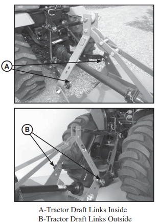
- Install tractor draft links on hitch pins. Secure with quick-lock pins (stored on tractor draft links).
- Align the center link with the upper hole in the cutter mast straps and install the center link mounting hardware.
- See ATTACHING PTO DRIVELINE in this section.
- Start the tractor engine.
- Slowly pull the hitch control lever to raise the cutter. Check for interference. (See CHECKING DRIVELINE/CUTTER CLEARANCE in this section.)
- Lower the hitch to the ground and adjust the center link and/or lift links if necessary. (See procedures in your tractor Operator’s Manual.)
Assembling PTO Driveline Telescoping Members (If Necessary)
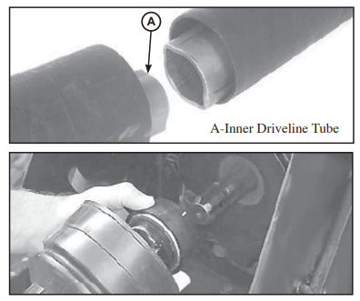
- Apply multipurpose grease around the outside surface of the inner driveline tube (A).
- Align driveline halves and assemble telescoping members.
- Apply multipurpose grease, or equivalent, to all lubrication fittings before operating. (See Lubrication and Maintenance section.)
Attaching PTO Driveline
- Shut off the tractor engine.
- Raise tractor PTO shield, if equipped.
- Support the driveline, cradling it in your hand.
- Pull the collar back toward the cutter. Align splines by rotating the cutter driveline. Push the driveline onto the tractor PTO shaft until the collar snaps into place.
- Pull back on the shield to make sure the driveline is locked.
- Do not pull back on the collar; this will release the latch.
- Lower tractor PTO shield, if equipped.
- Slip clutch operational check. After the implant has been stored for thirty days
Or perform the following operational check.- a. Loosen bolts and lock nuts progressively until tension is relieved.
- b. To aid in determining slippage, scribe/mark a line across the clutch plate and the Belleville Spring.
- c. With tractor at idle speed, engage tractor PTO drive 2 – 3 seconds. The clutch should slip without turning blades. If the clutch does not slip, contact
your authorized dealer. - d. Tighten bolts and lock nuts progressively, leaving a gap of 4mm between the clutch plate and Belleville spring.
DETACHING
Detaching Cutter from Tractor
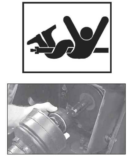
- Park the cutter on a level surface, or block the tailwheel so the machine cannot roll after detaching from the tractor.
- Slowly push the hitch control lever to lower the cutter close to the ground.
- Engage the tractor parking brake and/or place the transmission in “Park”
- Shut off the tractor engine and remove the key.
- Raise tractor PTO shield, if equipped.
- Pull the collar back toward the cutter and slide the driveline off the tractor shaft.
- Support and collapse the driveline completely and lower onto the PTO holder.
- Lower tractor PTO shield, if equipped.
Tractor with Quick Coupler Hitch
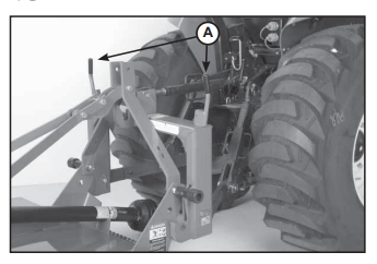
- Raise both latch control levers on the quick coupler (A).
- Start the tractor engine.
- Lower the cutter to the ground. Continue lowering the quick coupler until the hooks clear the cutter hitch pins.
- Carefully drive the tractor away
Tractor with Three-Point Hitch
- Remove quick-lock pins from hitch pins and install in storage position on tractor draft links.
- Remove and lower tractor draft links from hitch pins.
- Disconnect the center link from the mast straps. Position the tractor center link in the transport location. Reinstall the center link pin/hardware.
- Carefully drive the tractor away.
OPERATION
General Safety
Only qualified people should operate this machine. Wear close-fitting clothing and safety equipment appropriate to the job. It is recommended that the ractor be equipped with Rollover Protective Systems (ROPS) and a seat belt be used. Before beginning operation, clear the work area of objects that may be picked up and thrown. Check for ditches, stumps, holes or other obstacles that could upset the tractor or damage the rotary cutter. Always turn off the tractor engine, set the parking brake, and allow the rotary cutter blades to come to a complete stop before dismounting the tractor.
Preparing Cutter for Operation
- Adjust tractor rockshaft rate-of-drop. Allow at least two seconds for the machine to lower from full lift height to the ground. (See your tractor Operator’s Manual.)
- If equipped, disengage the tractor hitch/rockshaft control lever from the transport lock position and lower the cutter to the ground. (See your tractor Operator’s Manual.)
- Adjust the tractor lift level links the machine side-to-side. (See your tractor Operator’s Manual.)
- Adjust cutting height and angle. (See Adjusting Cutting Height and Angle in this section.)
LUBRICATION and MAINTENANCE
Lubricating and Maintaining Machine Safely
Components will be hot after the operation. Let all components cool before servicing. Replace all shields after lubricating or servicing.
Maintenance Check List
Perform scheduled maintenance as outlined below. Lower the machine to the ground, turn off the tractor, and set the parking brake before doing maintenance inspections or work. All bolts should be torqued as recommended in the Torque Specifications unless otherwise indicated.
Maintenance Before Each Use
- Check tractor tire air pressure. Refer to the tractor operator’s manual.
- Check blades and spindles to be sure that no foreign objects, such as wire or steel strapping bands, are wrapped around them.
- Check blade bolts for tightness. (Tighten to 425 ft./lbs.)
- Inspect blades for wear. (See SERVICE SECTION Checking Blade Wear. Always replace both blades on the blade holder with genuine Frontier parts.
- Make certain driveline shields are in place and in good repair.
- Inspect the tailwheel for wear, damage, or foreign objects. (Repair or replace if necessary.)
- Before each use, refer to LUBRICATION LOCATIONS AND INTERVALS in this section.
- During operation, listen for abnormal sounds which might indicate a loose part, damaged bearings, or other damage.
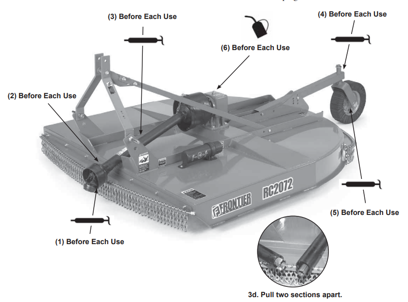
Lubrication Before Each Use
- Driveline Universal Joints:
- a. Apply multi-purpose grease with a grease gun.
- Driveline Guard
- b. Apply 2-3 shots of multipurpose grease with a grease gun to the plastic fitting.
- Driveline Profile
- c. Disconnect PTO Driveline.
- d. Pull two sections apart.
- e. Apply a thin coat of multi-purpose grease to the inside of the female section.
- f. Reassemble sections. Note: Pull each section to be sure the driveline and shields are securely connected. Make certain PTO shielding is in good condition. Do not grease outer or inner plastic shields.
- Tailwheel Pivot Tube
- g. Apply multi-purpose grease with a grease gun. (For dual wheel models of the RC2084, grease both pivot tubes.)
- Tailwheel
- h. Apply multi-purpose grease with a grease gun. (For dual wheel models of the RC2084, grease both tailwheels.)
- Gearbox
- i. Check oil level by removing the oil level check plug on the side of the gearbox.
j. Add EP80-90W gear oil if necessary to bring the oil level to check
- i. Check oil level by removing the oil level check plug on the side of the gearbox.
SERVICE
Practice Safe Service Procedures
- Lower the machine to the ground.
- Engage the tractor parking brake and/or place transmission in “Park”.
- Disengage PTO.
- Shut off the tractor engine and remove the key.
- Wait until all moving parts have stopped.
- Disconnect the PTO driveline from the tractor.
The blades and blade pan may rotate for several minutes after the PTO is shut off. Look and listen for the rotating driveline to stop before working on the cutter. When servicing blades or the blade pan, it will be necessary to work underneath the cutter. Be sure to support the cutter frame at all four corner locations with safety shop stands to prevent accidental lowering. Do not position safety stands under wheel support because these components can rotate.
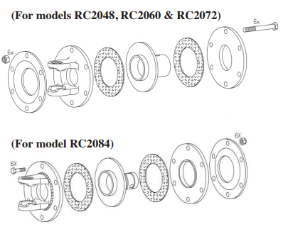
Disassembling and Inspecting Slip Clutch
- Remove the slip clutch driveline. (See procedure in this section.)
- Loosen bolts and lock nuts progressively until tension is relieved.
- Friction disks may appear to be part of the hub or yoke; tap lightly on the edge to separate.
- Inspect clutch components for wear or damage. Repair or replace part
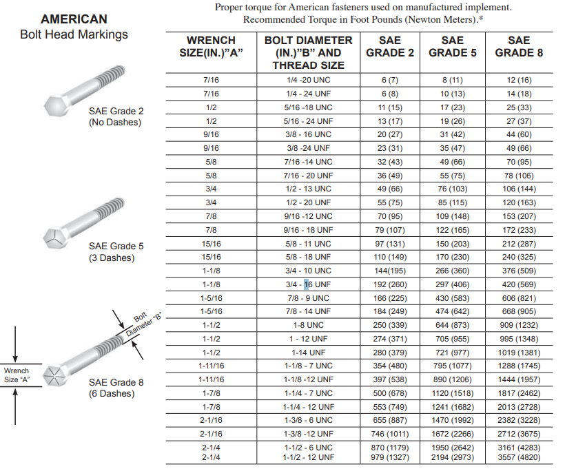
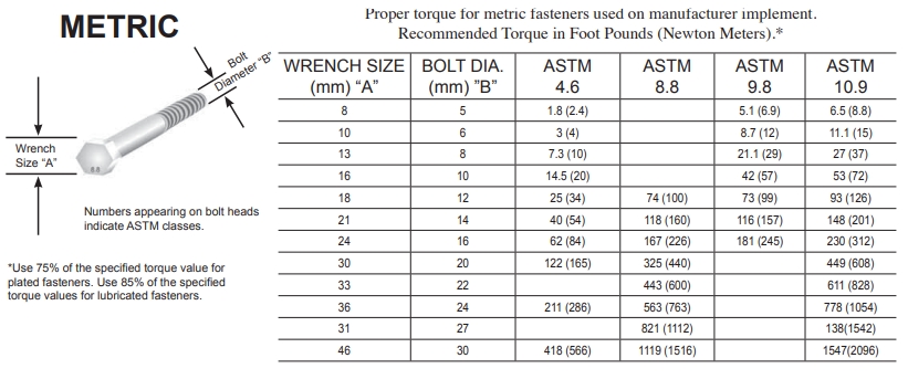
TORQUE SPECIFICATIONS
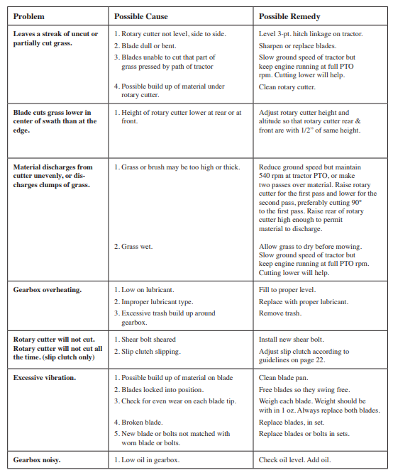
TROUBLESHOOTING GUIDE
FOR MORE MANUALS BY BLOGS, VISIT MANUALSLIBRARYY
Frontier 20 Series Rotary Cutter-FAQs
What is a Frontier 20 Series Rotary Cutter?
The Frontier 20 Series Rotary Cutter is a heavy-duty implement designed for cutting grass, weeds, and light brush. It is compatible with tractors using Category 1 or 2 hitches and PTO ranging from 18–90 horsepower.
How does a rotary cutter work?
A rotary cutter uses sharp rotating blades powered by the tractor’s PTO. As the blades spin at high speed, they cut through vegetation, making it useful for maintaining fields, pastures, and roadsides.
What are two important safety rules when using a rotary cutter?
Always operate the cutter away from people or animals, and never attempt to clear blockages while the machine is running. Keep shields and guards in place to avoid accidents.
How do I adjust the cutting height of the Frontier rotary cutter?
The cutting height can be adjusted by repositioning the tail wheel and using the tractor’s three-point hitch settings. Refer to the manual for recommended heights based on terrain.
What type of oil or lubrication does the cutter require?
The gearbox typically requires high-quality gear oil (SAE 80W-90). Grease fittings on the driveline and pivot points should also be lubricated regularly for smooth operation.
How do I maintain my rotary cutter?
Inspect blades, gearbox oil, and driveline regularly. Sharpen or replace dull blades, keep bolts tight, grease moving parts, and clean debris after each use.
What is the difference between the RC20 and RC40 models?
The RC20 is designed for lower flow rates (up to 16 gpm), while the RC40 can handle higher flow rates (up to 53 gpm). The RC40 is better suited for heavier-duty work.
Who makes Frontier equipment?
Frontier implements, including rotary cutters, are manufactured by John Deere’s Frontier Equipment line, providing durable solutions for farming and land management.

