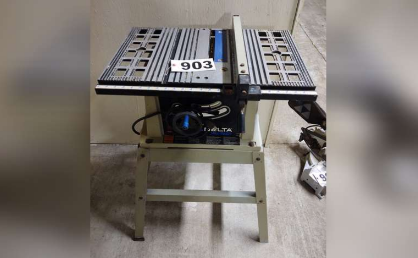
Delta TS200LS 10-inch Motorized Bench Saw

CARTON CONTENTS
MOTORIZED BENCH SAW PARTS
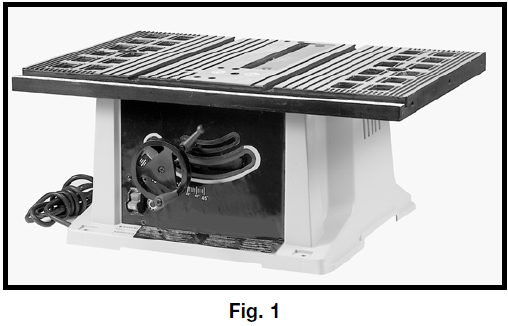
Fig. 1 illustrates the saw removed from the container. Figs. 2 and 3 illustrate the loose items packed with the saw. Fig. 4 illustrates the loose items packed for the stand for model TS-200LS ONLY.
Fig. 2 Parts
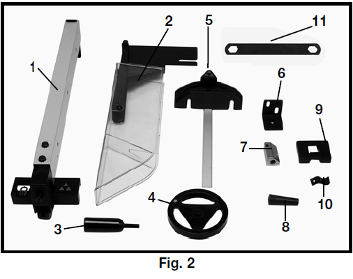
- Rip Fence
- Splitter and Guard Assembly
- Lock Handle for Rip Fence
- Blade Raising and Lowering Handwheel
- Miter Gage
- Splitter Support Bracket
- Splitter Bracket
- Handle for Blade Raising and Lowering Handwheel
- Miter Gage Holder
- Spring Clip for Miter Gage Holder
- Blade Wrench
Fig. 3 Hardware
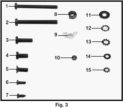
- M6x1x55mm Pan Head Screw (1)
- 1/4-20×2½” Hex Head Screw (1)
- M6x1x20mm Hex Head Screw (1)
- 1/4-20×1/2″ Hex Head Screw (2)
- M6x1x12mm Flat Head Screw (1)
- M4x.7x10mm Pan Head Screw (1)
- M4x.2x10mm Pan Head Screw (4)
- M8x1.25 Hex Nut (1)
- M6x1 Wing Nut (1)
- M4.7 Hex Nut (1)
- M6.4 Flat Washer (3)
- 1/4″ Internal Tooth Lockwasher (1)
- 1/4″ External Tooth Lockwasher (5)
- 3/16″ Flat Washer (4)
- 3/16″ External Tooth Flat Washer (1)
STAND FOR MODEL TS200LS ONLY (Fig. 4)
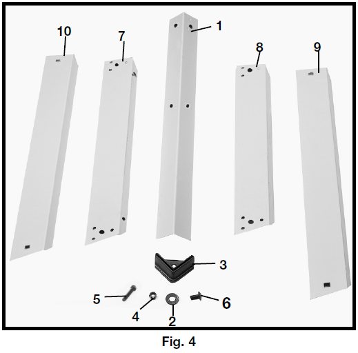
- Leg (4)
- 3/8” Flat Washer for Mounting Saw to Stand & for Assembling Stand (24)
- Foot (4)
- M8x1.25 Hex Nut for Mounting Saw to Stand & for Assembling Stand (20)
- M8x1.25x40mm Hex Screw for Mounting Saw to Stand (4)
- M8x1.25x20mm Carriage Head Bolts for Assembling Stand (16)
- 18-1/2” Top Front and Rear Brackets (2)
- 17” Top Side Brackets (2)
- 22” Bottom Front and Rear Brackets (2)
- 20-3/8” Bottom Side Brackets (2)
UNPACKING AND CLEANING
Carefully unpack the machine and all loose items from the shipping container(s). Remove the protective coating from all unpainted surfaces. This coating may be removed with a soft cloth moistened with kerosene (do not use acetone, gasoline, or lacquer thinner for this purpose). After cleaning, cover the unpainted surfaces with a good-quality household floor paste wax.
ASSEMBLY
ASSEMBLY TOOLS REQUIRED
(None supplied)
* Phillips head screw driver
* 13mm wrench for stand bolts
* 10mm wrench for splitter assembly bolts
* Straight edge and/or framing square for adjustments
ASSEMBLY TIME ESTIMATE – 1 hour
ELEVATING AND SUPPORTING SURFACES FOR A SAW WITH NO STAND
![]() WARNING: THE SAW MUST BE PROPERLY SECURED TO A SUPPORTING SURFACE. ALSO, FAILURE TO PROVIDE A SAWDUST FALL-THROUGH AND REMOVAL HOLE WILL ALLOW SAWDUST TO BUILD UP AROUND THE MOTOR, CAUSING A POSSIBLE FIRE HAZARD AND/OR MOTOR DAMAGE.
WARNING: THE SAW MUST BE PROPERLY SECURED TO A SUPPORTING SURFACE. ALSO, FAILURE TO PROVIDE A SAWDUST FALL-THROUGH AND REMOVAL HOLE WILL ALLOW SAWDUST TO BUILD UP AROUND THE MOTOR, CAUSING A POSSIBLE FIRE HAZARD AND/OR MOTOR DAMAGE.
![]() WARNING: DISCONNECT THE MACHINE FROM THE POWER SOURCE.
WARNING: DISCONNECT THE MACHINE FROM THE POWER SOURCE.
The saw must be elevated enough for sawdust to fall through the bottom of the saw and not build up around the motor.
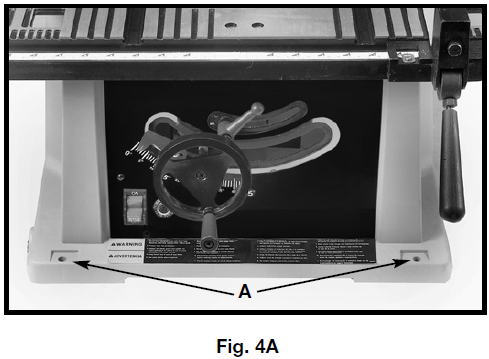
Position the four mounting holes located on the base of the saw cabinet (two of which are shown at (A) Fig. 4A) over whatever proper support you are using. Then securely fasten the saw to the supports. The saw can be secured by fastening the stand through the mounting holes with suitable hardware (not supplied).
![]() WARNING: THE SAW SUPPORT MUST BE STABLE AND ABLE TO SUPPORT 300 POUNDS.
WARNING: THE SAW SUPPORT MUST BE STABLE AND ABLE TO SUPPORT 300 POUNDS.
You can also construct a simple elevated support, as shown in Fig. 4B.
![]() WARNING: USE A GOOD GRADE OF PLYWOOD WITH A MINIMUM 3/4″ THICKNESS. DO NOT MAKE THE MOUNTING BOARD FROM PARTICLE BOARD SINCE PARTICLE BOARD BREAKS EASILY.
WARNING: USE A GOOD GRADE OF PLYWOOD WITH A MINIMUM 3/4″ THICKNESS. DO NOT MAKE THE MOUNTING BOARD FROM PARTICLE BOARD SINCE PARTICLE BOARD BREAKS EASILY.
![]() WARNING: A HOLE MUST BE PROVIDED IN THIS SUPPORT TO ALLOW SAWDUST TO FALL THROUGH.
WARNING: A HOLE MUST BE PROVIDED IN THIS SUPPORT TO ALLOW SAWDUST TO FALL THROUGH.
Square the saw on the supporting surface and mark the location for four 5/16 inch holes to be drilled (Fig. 4B).
![]() WARNING: MAKE SURE THERE IS AT LEAST 3″ ON ALL FOUR SIDES OF THE BASE.
WARNING: MAKE SURE THERE IS AT LEAST 3″ ON ALL FOUR SIDES OF THE BASE.
Set the saw aside and then drill holes in these marks. Locate and mark an 11″ or 12″ square centered between the four mounting holes. Cut out and remove the square (Fig. 4B).
To elevate the supporting surface, measure two 2x4s (A), Fig. 4B, to the width of two opposite sides of the supporting surface. Attach the supporting surface to the narrow edges of the 2X4s (as shown in Fig. 4B) using wood screws (not provided) in at least three spots (B) Fig. 4B on each side.
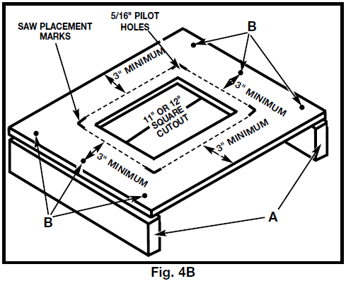
Fasten the saw to the surface by inserting suitable hardware (not supplied) through the mounting holes on the saw and into the previously drilled holes. While using the saw, periodically remove the sawdust buildup from below the saw.
ASSEMBLING STAND FOR MODEL TS200LS
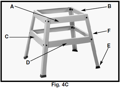
- Assemble the stand as shown in Fig. 4C, using 16 M8x1.25x20mm carriage head bolts, 3/8″ flat washers, and M8x1.25 hex nuts. Align the holes in the stand legs (F) with the holes in the brackets. Insert the carriage head bolt through the hole in the leg and the hole in the bracket. Place a flat washer on the carriage head bolt and thread a hex nut onto the carriage head bolt. Repeat this process for the 15 remaining holes in the legs and brackets.
 NOTE: Loosely tighten the hardware for further adjustment.
Letters are on the stand brackets to ease assembly:- A – Top front and rear brackets
- B – Top side brackets
- C – Bottom side brackets
- D – Bottom front and rear brackets
- Attach the rubber feet (E), Fig. 4C, to the bottom of each leg (F).
NOTE: Each rubber foot is provided with holes for mounting the stand to the floor surface if required.
SAW TO STAND – TS200LS ONLY
- Turn the saw table face down on a piece of cardboard to protect the table surface. Place the stand upside down onto the saw and align the four holes in the stand with the mounting holes in the saw.
- Place a 3/8″ flat washer on an M8x1.25x40mm hex head screw. Insert the hex head screw through the mounting hole in the saw and the mounting hole in the stand. Place another 3/8″ flat washer on the hex head screw and thread an M8x1.25 hex nut on the screw and loosely tighten. Complete this process for the other three holes.
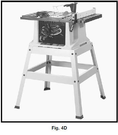
- Stand the saw upright, as shown in Fig. 4D (Saw is shown fully assembled here).

- Push down on top of the saw so that the legs of the stand adjust to the surface of the floor. Tighten all hardware securely.
ATTACHING BLADE HEIGHT ADJUSTING HANDWHEEL
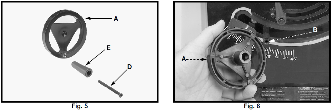
- Insert an M6x1x55mm pan head screw (D) Fig. 5 through the handle (E). Attach the handle (E) to the handwheel (A) by threading the screw (D) clockwise into the handwheel.
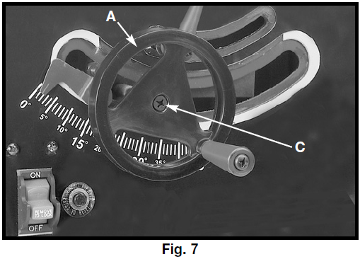
- Attach the handwheel (A), Fig. 6, to the shaft (B). Align the flat on the inside of the handwheel to the flat on the shaft.

- Fasten the handwheel (A) Fig. 7 to the shaft using an M6x1x12mm flat head screw (C)

ATTACHING BLADE GUARD AND SPLITTER ASSEMBLY
![]() WARNING: DISCONNECT THE MACHINE FROM THE POWER SOURCE.
WARNING: DISCONNECT THE MACHINE FROM THE POWER SOURCE.
![]() WARNING: PROPERLY ALIGN THE BLADE GUARD AND SPLITTER ASSEMBLY WITH THE SAW BLADE TO PREVENT KICKBACK.
WARNING: PROPERLY ALIGN THE BLADE GUARD AND SPLITTER ASSEMBLY WITH THE SAW BLADE TO PREVENT KICKBACK.
- Position the blade 90 degrees to the table and lock it in place.
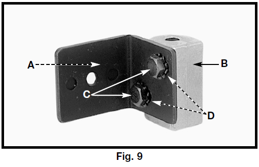
- Fasten the splitter support bracket (A), Fig. 9, to the splitter bracket (B) using two 1/4-20×1/2″ hex head screws (C) and two 1/4″ external tooth lockwashers(D).
 NOTE: Loosely tighten the screws for further adjustment.
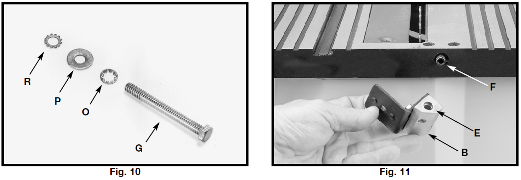
 - Locate the 1/4-20×2½” hex head screw (G), Fig. 10. Place the 1/4″ internal tooth lockwasher (O), M6.4 flat washer (P), and the 1/4″ external tooth lockwasher (R) on the screw (G).
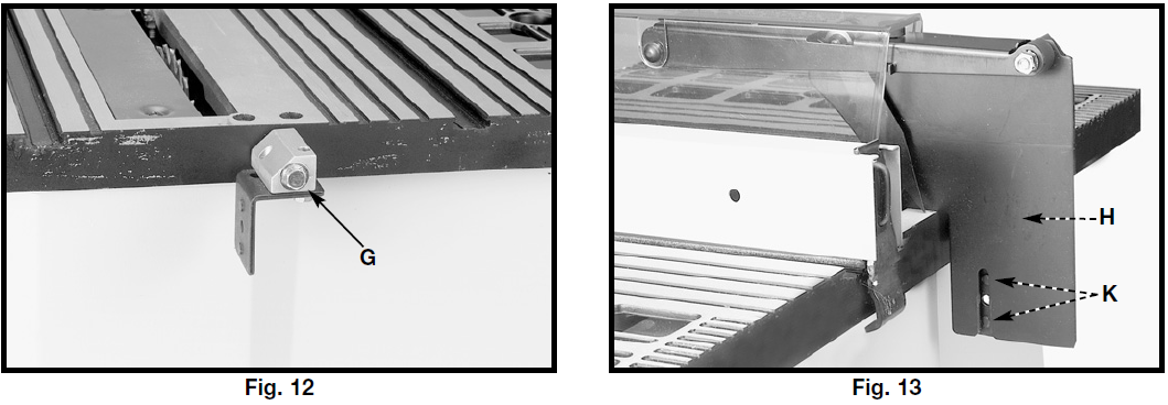
- Position the recessed end (E) Fig. 11 of the splitter bracket (B) against the end of the pivot rod (F), and fasten using the assembly in STEP 3.
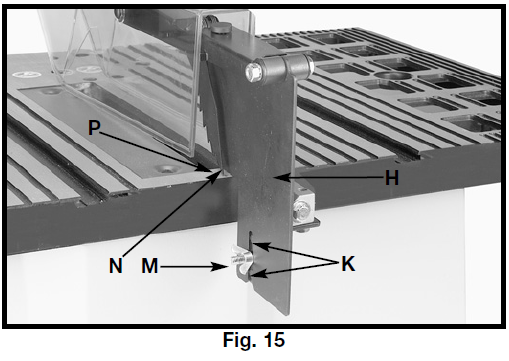
NOTE: Loosely tighten the hardware for further adjustment. - Position the splitter (H), Fig. 13,, against the splitter support bracket, making certain the two protrusions (K) on the splitter support bracket are inside the slot of the splitter (H).


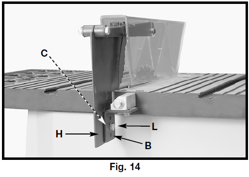
- Attach the splitter (H), Fig. 14, to the splitter support bracket (B). Place a 1/4″ external tooth lockwasher and an M6.4 flat washer on an M6x1x20mm hex head screw (L).
- Insert the screw (L) Fig. 14 through the splitter support bracket (C) and the splitter (H). Place an M6.4 flat washer and a 1/4″ external tooth lock washer on the screw (L). Thread an M6x1 wing nut (M) Fig. 15 on the screw (L) Fig. 15.
 NOTE: Before tightening the wing nut (M) Fig. 15, make certain a gap of at least 1/8″ is between the bottom edge of the splitter (N) and the top surface of the table (P) and that the protrusions (K) are inside the slot of the splitter assembly (H).
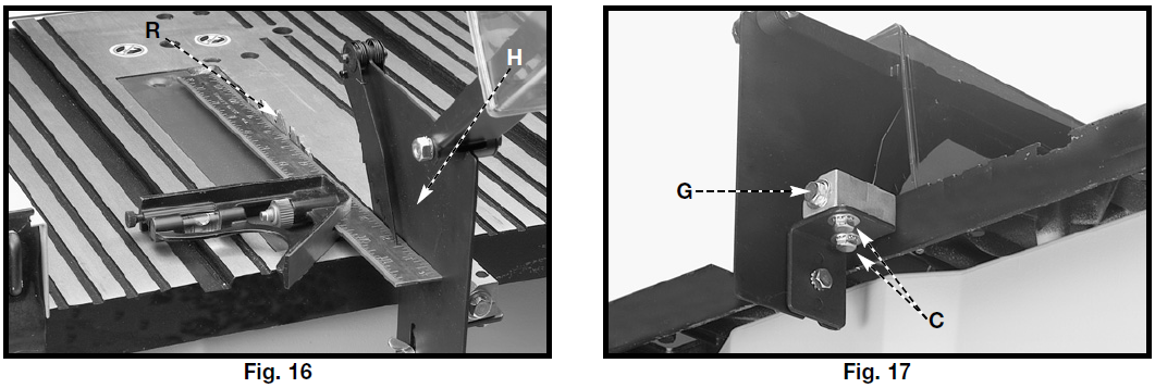
- Use a straight edge to see if the splitter (H), Fig. 16, is aligned with the saw blade (R). If an adjustment is necessary, the splitter (H) can be moved left or right and rotated.
- When the splitter is properly aligned with the saw blade, tighten the screws (C) and (G),, Fig. 17.

MITER GAUGE
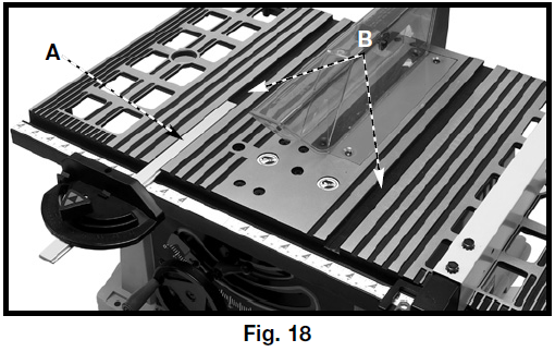
The miter gauge is shipped assembled and is supplied with a T-slot bar (A), Fig. 18, that is inserted into either one of the two T-slotted miter gauge grooves (B) located in the table top. The T-slot prevents the miter gauge from falling when it is extended beyond the front of the table when cross-cutting extra-wide workpieces.
ATTACHING MITER GAUGE HOLDER
![]() WARNING: DISCONNECT THE MACHINE FROM THE POWER SOURCE.
WARNING: DISCONNECT THE MACHINE FROM THE POWER SOURCE.

- Attach the spring clip (E) Fig. 19 to the miter gauge holder (A) using an M4x.7x10mm pan head screw (F), 3/16″ external tooth lockwasher (B), and M4x.7 hex nut.
NOTE: The hex nut, (G) Fig. 20, will fit into the recess at the back of the miter gauge holder (A), Fig. 19, to keep the spring clip (E) secured to the miter gauge holder. - Attach the miter gauge holder (A) Fig. 21 to the left side of the saw cabinet using the four M4x.2x10mm screws (B) Fig. 22, and 3/16″ flat washers (C) from inside the saw cabinet.
- Fig. 23 illustrates the miter gauge (D) inserted into the holder.


ASSEMBLING RIP FENCE
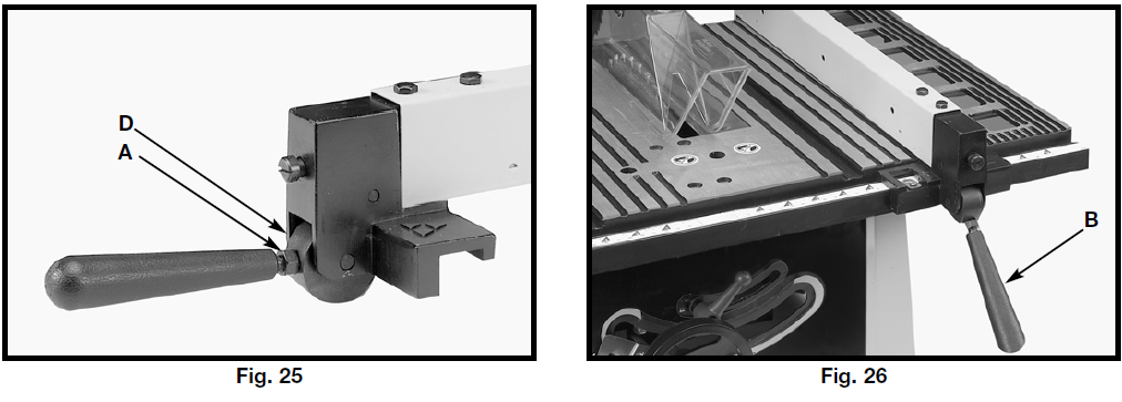
- Thread the M8x1.25 hex nut (A), Fig. 24, approximately halfway on the stud of the handle (B).
- Thread the handle (B) Fig. 24 into the tapped hole (C) in the fence cam (D). Tighten the hex nut (A) Fig. 25 against the cam (D).
- The rip fence is usually set up on right-handhand side of the saw table. Lift the lock handle (B), Fig. 26, and position the fence on the table. Push down on the handle (B), Fig. 26, to lock the fence in place.
OPERATION
OPERATIONAL CONTROLS AND ADJUSTMENTS
STARTING AND STOPPING THE SAW
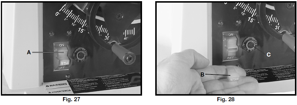
The on/off switch (A), Fig. 27, is located on the front of the saw cabinet. To turn the saw “ON”, move the switch (A) up to the “ON” position. To turn the saw “OFF”, move the switch (A) down to the “OFF” position.
![]() WARNING: MAKE SURE THAT THE SWITCH IS IN THE “OFF” POSITION BEFORE PLUGGING IN THE POWER CORD. IN THE EVENT OF A POWER FAILURE, MOVE THE SWITCH TO THE “OFF” POSITION. AN ACCIDENTAL START-UP CAN CAUSE INJURY.
WARNING: MAKE SURE THAT THE SWITCH IS IN THE “OFF” POSITION BEFORE PLUGGING IN THE POWER CORD. IN THE EVENT OF A POWER FAILURE, MOVE THE SWITCH TO THE “OFF” POSITION. AN ACCIDENTAL START-UP CAN CAUSE INJURY.
LOCKING SWITCH IN THE “OFF” POSITION
IMPORTANT: When the tool is not in use, the switch should be locked in the “OFF” position to prevent unauthorized use. To lock the tool, grasp the switch toggle (B) and pull it out of the switch (Fig. 28). With the switch toggle (B) removed, the switch will not operate. However, should the switch toggle be removed while the saw is running, the machine can be turned “OFF,” but cannot be restarted without re-inserting the switch toggle (B).
OVERLOAD PROTECTION
Your saw is equipped with a reset button (C) Fig. 28. If the motor stops or fails to start dueoverloadingding (cutting stock too fast, using a dull blade, using the saw beyond its capacity, etc.) or low voltage, turn the switch to the “OFF” position. Let the motor cool for three to five minutes. Push the reset button (C) to reset the overload device. The motor can then be started again in the usual manner.
BLADE HEIGHT ADJUSTMENT
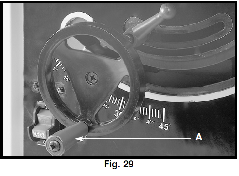
To adjust the height of the saw blade, turn the handwheel (A) Fig. 29. Turning the handwheel clockwise lowers the blade, and turning the handwheel counterclockwise raises the blade.
BLADE TILT ADJUSTMENT
To tilt the saw blade, loosen the lock handle (A), Fig. 30, and move the handwheel (B) until the blade is at the desired angle. Tighten the lock handle (A).
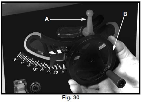
NOTE: The lock handle (A) is spring-loaded. Pull out on the handle (A) and reposition it on the serrated stud located underneath the handle.
![]() WARNING: THE BLADE TILTING LOCK HANDLE (A) MUST BE LOCKED DURING ALL CUTTING OPERATIONS.
WARNING: THE BLADE TILTING LOCK HANDLE (A) MUST BE LOCKED DURING ALL CUTTING OPERATIONS.
90 AND 45 DEGREE POSITIVE STOP ADJUSTMENTS
Your saw is equipped with positive stops for rapid and accurate positioning of the saw blade at 90 and 45 degrees to the table.
![]() WARNING: DISCONNECT THE MACHINE FROM THE POWER SOURCE.
WARNING: DISCONNECT THE MACHINE FROM THE POWER SOURCE.
TO ADJUST POSITIVE STOP AT 90 DEGREES
- Raise the saw blade to its maximum height.
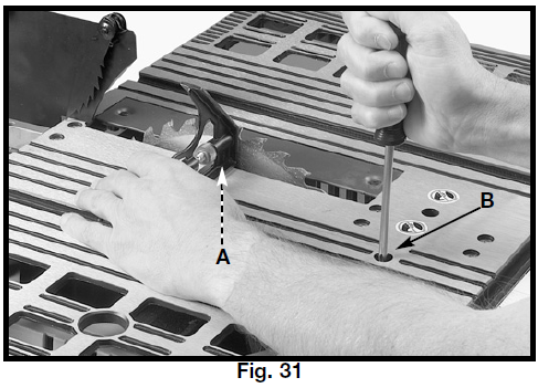
- Loosen the blade tilting lock handl, (A,) Fig. 30, move the blade tilting mechanism (B) as far as possible to the left, and tighten the blade tilting lock handle (A).
- Place a square (A) Fig. 31 on the table with one end of the square against the blade, and check to see if the blade is 90 degrees to the table. If not, loosen the screw (B) Fig. 31 a few turns and move the blade tilting mechanism until the blade is 90 degrees to the table. Tighten the blade tilting lock handle (A) Fig. 30, and tighten the screw (B) Fig. 31 until it stops.
TO ADJUST POSITIVE STOP AT 45 DEGREES
- Raise the saw blade to its maximum height.
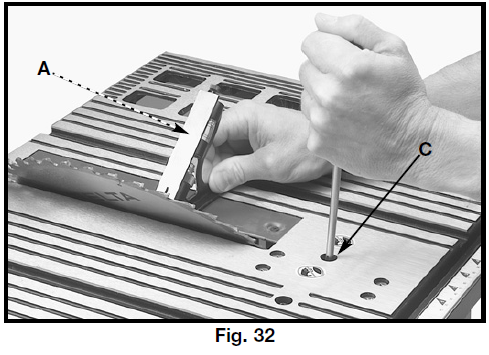
- Loosen the blade tilting lock handle (A), Fig. 31, move the blade tilting mechanism (B) as far as possible to the right, and tighten the blade tilting lock handle (A).
- Place a square (A) Fig. 32 on the table with one end of the square against the blade, and see if the blade is 45 degrees to the table. If not, loosen the screw (C) Fig. 32 a few turns and move the blade tilting mechanism (B) Fig. 30, until the blade is 45 degrees to the table. Tighten the blade tilting lock handle (A) Fig. 30, and tighten the screw (C) Fig. 32 until it stops.
RIP FENCE OPERATION AND ADJUSTMENTS
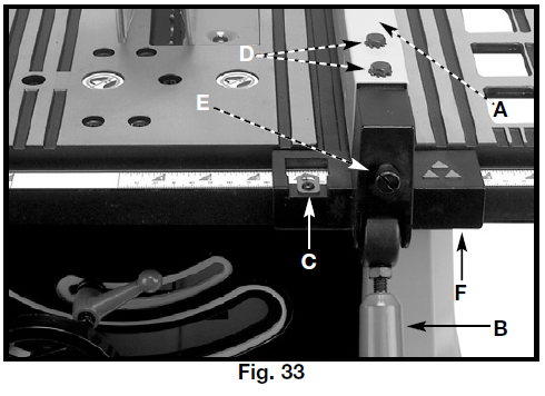
- To move the rip fence (A) Fig. 33 along the table, lift the fence locking lever (B), slide the fence to the desired location on the table, and push down the fence locking lever (B).
- The pointer indicates the distance from the fence to the saw blade. If an adjustment is required, loosen the screw (C), Fig. 3,7, and adjust.
IMPORTANT: The rip fence must be properly aligned to the miter gauge slot to prevent kickback when ripping. - The saw blade is set parallel to the miter gauge slot at the factory. The fence must be parallel to the miter gauge slot to do accurate work and to prevent kickback when ripping. To check the alignment:
- Position the fence next to the miter gauge slot (Fig. 33). Clamp the fence to the table by pushing the locking lever (B) down. The edge of the fence should be parallel to the miter gauge slot.

- If an adjustment is necessary, loosen the two screws (D), Fig. 33, and lift the locking lever (B). While holding the fence bracket (F) firmly toward the front of the saw, move the rear of the fence (A) until it is parallel with the miter gauge slot. Tighten two screws (D) anthehe h locking lever down (B).
- Adjust the clamping action of the fence (A) Fig. 33 by lifting the locking lever (B) and turning the screw (E) clockwise to increase, or counterclockwise to decrease the clamping action of the fence.
TABLE INSERT ADJUSTMENT
![]() WARNING: DISCONNECT THE MACHINE FROM THE POWER SOURCE.
WARNING: DISCONNECT THE MACHINE FROM THE POWER SOURCE.
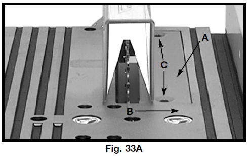
- Make sure that the table insert (A), Fig. 33A, is flush with, or slightly below, the surface of the table (B).
- If the table insert is above the surface of the table, tighten the two table insert screws (C),, Fig. 33A, to lower the insert.

MITER GAUGE OPERATION AND ADJUSTMENTS
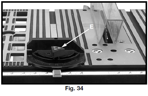
For cross-cutting (blade set 90 degrees to the table), the miter gauge can be used in either table slot. For bevel cross-cutting (with the blade tilted), use the miter gauge in the right table slot only so that the blade will be tilted away from the miter gauge and your hands.
To operate the miter gauge, loosen the lock knob (E), Fig. 34, and rotate the miter gauge to the desired angle.
ADJUSTING BLADE PARALLEL TO MITER GAUGE SLOTS
The blade was adjusted parallel to the miter gauge slots at the factory. In order to ensure accurate cuts and help prevent kickback, check this adjustment.
To adjust:
![]() WARNING: DISCONNECT THE MACHINE FROM THE POWER SOURCE.
WARNING: DISCONNECT THE MACHINE FROM THE POWER SOURCE.
- Raise the blade to its highest position and adjust the blade so that it is 90 degrees to the table.
- Select a tooth on the saw blade that is set to the left. Mark this tooth with a pencil or marker.
- Use a combination square (A) Fig. 35 against the miter gauge slot and adjust the blade (B) of the square until it touches the marked tooth.
- Rotate the blade and check the same marked blade tooth at the rear of the saw table (Fig. 36).

- If the front and back measurements (Figs. 35 and 36) are not identical, you can adjust the blade. Start by loosening the nuts below the four screws C, Fig. 37 on the table. Then loosen the screws (C). Carefully move the saw blade until the blade is parallel to the miter gauge slot. When done, tighten four nuts under the table and the four screws (C) Fig. 37 securely.
 NOTE: If sufficient adjustment cannot be achieved by loosening the screws (C) Fig. 37, loosen the screw (D) Fig. 37 necessary to madjust
CHANGING THE BLADE
![]() WARNING: DISCONNECT THE MACHINE FROM THE POWER SOURCE. USE ONLY 10″ DIAMETER SAW BLADES RATED FOR 4700 RPM OR HIGHER. USE ONLY SAW BLADES WITH 5/8″ ARBOR HOLES.
WARNING: DISCONNECT THE MACHINE FROM THE POWER SOURCE. USE ONLY 10″ DIAMETER SAW BLADES RATED FOR 4700 RPM OR HIGHER. USE ONLY SAW BLADES WITH 5/8″ ARBOR HOLES.
- NOTE: One 7/8″ wrench is supplied with the saw for changing the saw blade.
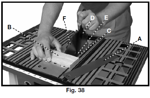
- Remove table insert (A) Fig. 38, and raise the saw blade (F) to its maximum height.

- To remove the blade, place the wrench (D) on the flats of the arbor nut (C) to keep the arbor from turning. Place a piece of wood (B) flat on the table against the blade so that a tooth of the blade can “grab” the wood to keep the blade from turning. Use a wrench to turn the arbor nut toward the front of the saw. Remove arbor nut, blade flange (E), and saw blade.
- Assemble the new blade, making certain the teeth point down at the front of the saw table, and assemble the outside blade flange and arbor nut. Using the piece of wood (B) to keep the blade from turtheen tighten tighten ng,thee ten arbor nut byturninge thg wrench (D) toward the rear of the saw.
- Replace table insert.
TROUBLESHOOTING
For assistance with your machine, visit our website at www.deltamachinery.com for a list of service centers or call the DELTA Machinery help line at 1-800-223-7278 (In Canada da call 1-800-463-3582).
MAINTENANCE
KEEP THE MACHINE CLEAN
Periodically blow out all air passages with dry compressed air. All plastic parts should be cleaned with ,,s damp cloth. NEVER use solvents to clean plastic parts. They could dissolve or otherwise damage the material.
![]() WARNING: Wear ANSI Z87.1 safety glasses while using compressed air.
WARNING: Wear ANSI Z87.1 safety glasses while using compressed air.
FAILURE TO START
Should your machine fail to start, check to make sure the prongs on the cord plug are making good contact in the outlet. Also, check for blown fuses or open circuit breakers in the line.
LUBRICATION
Apply household floor paste wax to the machine table and extension table or other work surface weekly.
PROTECTING CAST IRON FROM RUST
To clean and protect cast iron tables from rust, you will need the following materials: 1 pushblock from a jointer, 1 sheet of medium Scotch-Brite™ Blending Hand Pad, 1 can of WD-40®, 1 can odegreaserer,and 1 can of TopCote® Aerosol. Apply the WD-40 and polish the table surface with the Scotch-Brite pad using pushblockhold-downdown. Degrease the table, then apply the TopCote® accordingly.
SERVICE

PARTS, SERVICE, OR WARRANTY ASSISTANCE
All Delta Machines and accessories manufactured to high-qualitylity standards and are serviced by a network of Porter-Cable • Delta Factory Service Centers and Delta Authorized Service Stations. To obtain additional information regarding your Delta quality product or to obtain parts, service, warranty assistance, or the location of the nearest service outlet, please call 1-800-223-7278 (In Canada,da cal1-800-463-3582).
ACCESSORIES
A complete line of accessories is available from your Delta Supplier, Porter-Cable • Delta Factory Service Centers, and Delta Authorized Service Stations. Please visit our website www.deltamachinery.com for a catalog or for the name of your nearest supplier.
![]() WARNING: Since accessories other than those offered by Delta have not been tested with this product, use of such accessories could be hazardous. For the safest operation, only Delta-recommended accessories should be used with this product.
WARNING: Since accessories other than those offered by Delta have not been tested with this product, use of such accessories could be hazardous. For the safest operation, only Delta-recommended accessories should be used with this product.
WARRANTY

Two-Year Limited New Product Warranty
Delta will repair or replace, at its expense and at its option, any new Delta machine, machine part, or machine accessory which in normal use has proven to be defective in workmanship or material, provided that the customer returns the product prepaid to a Delta factory service center or authorized service station with proof of purchase of the product within two years and provides Delta with reasonable opportunity to verify the alleged defect by inspection. For all refurbished Delta products, the warranty period is 180 days. Delta may require that electric motors be returned prepaid to a motor manufacturer’s authorized station for inspection and repair or replacement. Delta will not be responsible for any asserted defect which has resulted from normal wear, misuse, abuse, or repair or alteration made or specifically authorized by anyone other than an authorized Delta service facility or representative. Under no circumstances will Delta be liable for incidental or consequential damages resulting from defective products. This warranty is Delta’s sole warranty and sets forth the customer’s exclusive remedy, with respect to defective products; all other warranties, express or implied, whether of merchantability, fitness for purpose, or otherwise, are expressly disclaimed by Delta.
For more manuals by Delta, visit ManualsLibraryy

 NOTE: Loosely tighten the hardware for further adjustment.
 NOTE: Loosely tighten the screws for further adjustment.
 NOTE: Before tightening the wing nut (M) Fig. 15, make certain a gap of at least 1/8″ is between the bottom edge of the splitter (N) and the top surface of the table (P) and that the protrusions (K) are inside the slot of the splitter assembly (H).

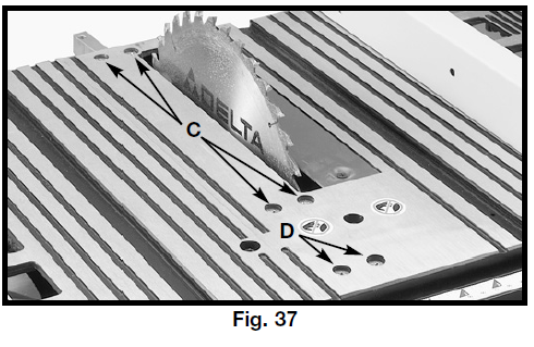 NOTE: If sufficient adjustment cannot be achieved by loosening the screws (C) Fig. 37, loosen the screw (D) Fig. 37 necessary to madjust