Garmin GSB 15 Dual-Port USB Charging Hub
Description and Identification
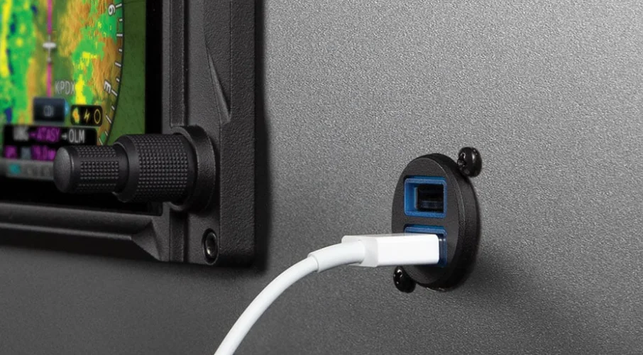
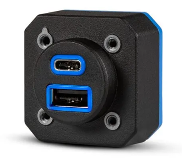
The GSB 15 functions as a USB Database and Charging Hub that provides:
- Two (2) – USB Type A charging ports (low-current with data transfer or high-current without data transfer)
- Optional software and database loading to compatible Garmin devices via USB
- Halo backlighting to facilitate nighttime usability
Unit Identification
The GSB 15 can be identified by the part numbers listed in Table 1-1.
The GSB 15 is currently available in the following configurations.
[1] Includes connector kit (011-05044-00)
Accessories
The following accessories are provided separately from the GSB 15.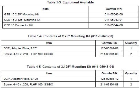

Performance Technical Specifications
Environmental Qualification Form Reference
It is the responsibility of the installing agency to obtain the latest revision of the GSB 15 Environmental Qualification Form. To obtain a copy of this form, see the dealer/OEM portion of the Garmin website (www.garmin.com).
This form is available directly from Garmin under the following part number:
GSB 15 Environmental Qualification Form, Garmin part number 005-01380-03
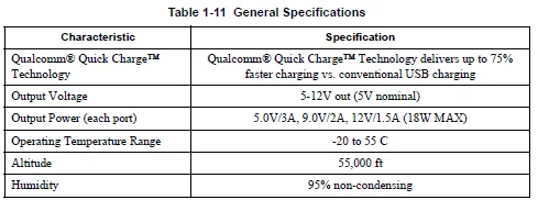
General Specifications
Power Specifications
Maximum power while charging both ports (18W each) and backlight enabled: 40W
- 28V: 1.43A
- 14V: 2.86A
Maximum power with no devices connected: 500mW
- 28V: 17mA
- 14V: 35mA
Over-Temperature Protection
The GSB 15 is equipped with over-temperature detection and may re-negotiate to 5V, 1.5A (MAX) output current. Once the device has cooled, normal output current will resume.
Operating Instructions
The GSB 15 has a configurable backlight. Grounding pin 5 will deactivate the backlight; allowing pin 5 to float enables the backlight.
It is acceptable and preferred to install only the pins that are needed.
CAUTION
Do not apply power to the unit until after the rear connector is completely seated.
Connecting the unit while power is applied may cause damage to the device and to other LRUs that are connected to the data lines.
INSTALLATION OVERVIEW
Introduction
This section provides the equipment information for installing the GSB 15 and related optional accessories. Installation of the GSB 15 must follow the data detailed in this manual. Cabling is typically fabricated by the installing agency to fit each particular aircraft.
Always follow acceptable avionics installation practices per advisory circulars AC 43.13-1B and AC 43.13-2B or later FAA-approved revisions.
Installation Materials Required but not Supplied
- All wiring required for installation
- Circuit breaker
Installation Configurations
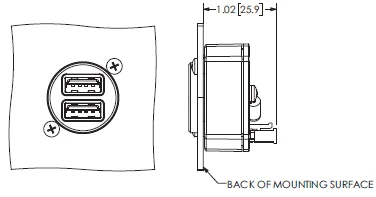
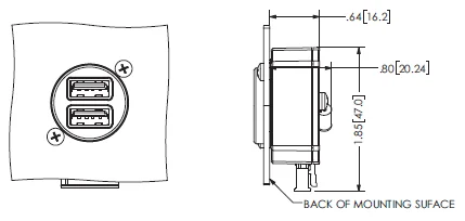
The GSB 15 can be installed in either a rear connector or side connector configuration. Refer to the outline and installation drawings in Appendix A.
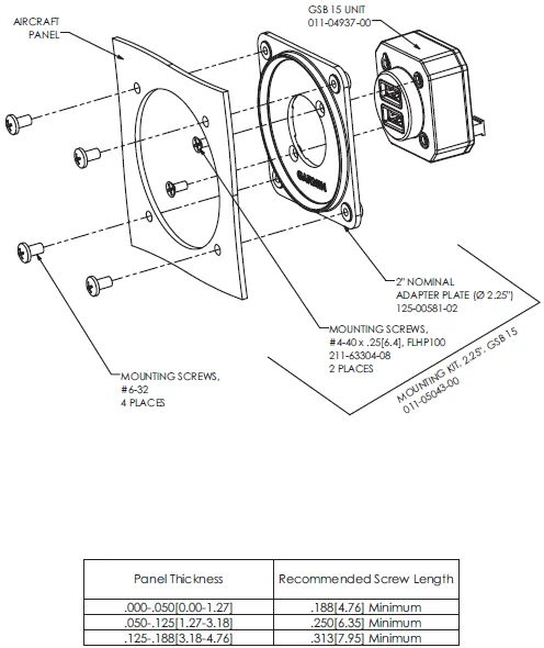
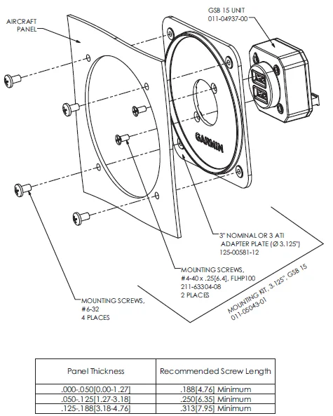
Optional 2.25” and 3.125” mounting kits are also available (see Table 1-3) to mount the GSB 15 in existing instrument panel holes.
NOTE
At least 2 of the 4 provided mounting holes must be used (diagonally from each other) to mount the GSB 15.
Special Tools Required
A crimp tool is required for the GSB 15 installation. Recommended and optional crimp tools are as follows:
Recommended Crimp tool:
Optional:
- Molex Insertion Tool for Micro-Fit 3.0 and CRC Male and Female Crimp Terminals, 20-30 AWG, P/N 638120800
- Molex Extraction Tool, P/N 11030043
Cabling and Wiring
Wiring must be installed in accordance with AC 43.13-1B Chapter 11, Sections 8 through 13. The following issues must be addressed:
- Do not expose cabling and wiring to chafing
- Do not route cabling and wiring harnesses near flight cables
- Do not route cabling and wiring near high-energy sources. (e.g., DC motors, high heat sources)
- Wiring indicated as shielded in Appendix B must be shielded
- Pigtail lengths must be less than 3.0 inches.
- Use 22 AWG or larger for power and ground wires, 25 ft max.
Shielding and Electrical Bonding Considerations
Electrical equipment, supporting brackets, and racks must be electrically bonded to the aircraft’s main structure or a designated aircraft groundplane. Refer to the following documents for applicable bonding techniques:
- AC 43.13-1B CHG 1, “Acceptable Methods, Techniques, and Practices – Aircraft Inspection and Repair”, Chapter 11, “Aircraft Electrical Systems”
- SAE ARP 1870A, “Aerospace Systems Electrical Bonding and Grounding for Electromagnetic Compatibility and Safety”
- A bonding procedure developed and supplied by the aircraft manufacturer (if available)
The electrical bond must achieve a direct current (DC) resistance of less than or equal to 2.5 milliohms to the local structure where the equipment is mounted. Compliance must be verified by inspection using a calibrated milliohm meter.
Cooling Requirements or Considerations
The GSB 15 has no cooling requirements or considerations. Forced air cooling will reduce the internal temperature of the unit and prolong the life of the product.
The GSB 15 is equipped with over-temperature detection that may reduce output current to 1.5A (max) .
After the device has cooled, the normal output current of 3A (max) will resume.
Mounting Requirements
The small size of the GSB 15 allows it to be installed in many places. It is intended to be installed on the instrument panel or other suitable cabin surface. There are no special requirements for viewing, reach, or proximity. See drawings in Appendix A for details.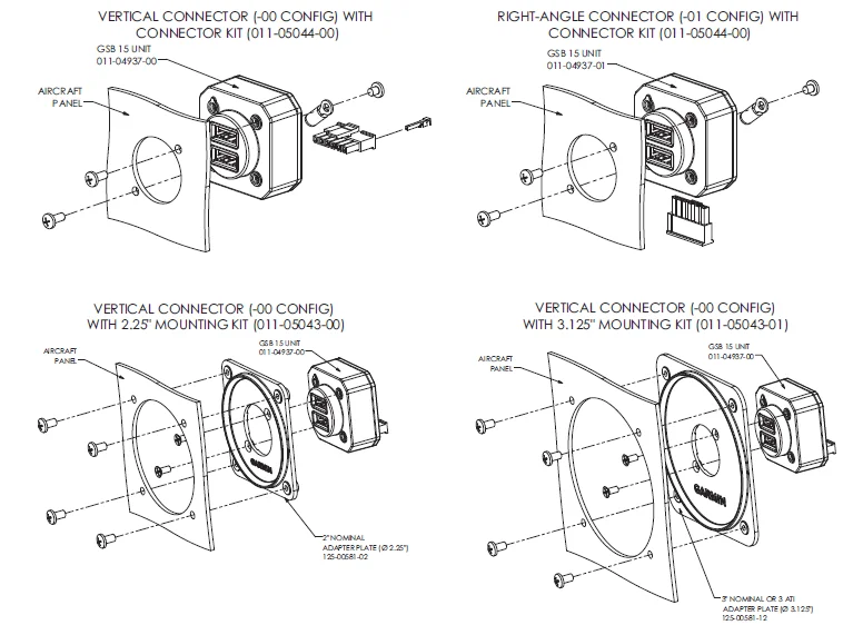
INSTALLATION PROCEDURE
Wiring Harness Installation
Allow adequate space for the installation of cables and connectors. The installer shall supply and fabricate all of the cables. All electrical connections are made through a single connector.
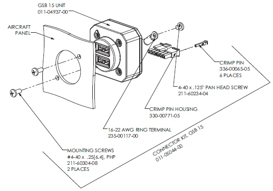
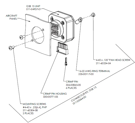
Section 6 defines the electrical characteristics of all input and output signals. Required connectors and associated hardware are provided in the connector kit (Section 1.2.2).
CAUTION
Do not apply power to the unit until after the rear connector is completely seated.
Connecting the unit while power is applied may cause damage to the device and to other LRUs that are connected to the data lines.
NOTE
For data transfer installations, the ring terminal is required. If used, torque the ring terminal screw to 4-6 in-lbs.
Equipment Mounting
For final installation and assembly, refer to the outline and installation drawings shown in Appendix A of this manual.
- Assemble the connector per the instructions in Section 2.
- Install the unit from the back side of the desired installation surface with the circular surface protruding through the hole.
- Attach the unit to the installation surface using a minimum of two screws (oriented diagonally). Rotation orientation of the unit within the mounting location is at the installer’s discretion.
- Attach the cable harness to the connector, paying attention to the keying and latching features of the connector.
- If using mounting kit 011-05043-00 or 011-05043-01, mount the adapter plate to the desired mounting surface using the specified screws (see Figure A-4) and attach the unit to the adapter plate using the included screws.
CAUTION
Be careful not to damage the unit or connector during installation. Avoid over-torquing mounting screws.
NOTE
For vertical unit (011-04937-00) installations, ensure the portion of the panel that mates to the GSB 15 is electrically conductive to ensure proper grounding.
Unit Replacement
Make sure that power is removed before removing the GSB 15.
POST INSTALLATION CONFIGURATION & CHECKOUT
Mounting, Wiring, and Power Checks
Verify all cables are properly secured and shields are connected to the ground lug located on the back of the unit. Check the movement of the flight and engine controls to verify there is no interference between the cabling and control systems. Verify all wiring is installed as described in this manual. Prior to installing and powering up the GSB 15, the wiring harness must be checked for proper connections to the aircraft systems and other avionics equipment. Point-to-point continuity must be checked to expose any faults, such as shorts to ground or wiring discrepancies. Any faults or discrepancies must be corrected before proceeding. After accomplishing a continuity check, perform power and ground checks to verify proper power distribution to the GSB 15. Any faults or discrepancies must be corrected at this time. The GSB 15 can be installed after completion of the continuity and power checks.
Configuration Setup
Not applicable.
Diagnostic Information
Not applicable.
Ground Checks
Not applicable.
Software Loading Procedure
The GSB 15 does not use or load its own operating software.
CONNECTOR PINOUT INFORMATION
Pin Function List
P201/202 Connector
NOTE
P201 is the rear connector designation for the GSB 15 (vertical) part number 011-04937-00.
NOTE
P202 is the rear connector designation for the GSB 15 (right angle) part number 011-04937-01.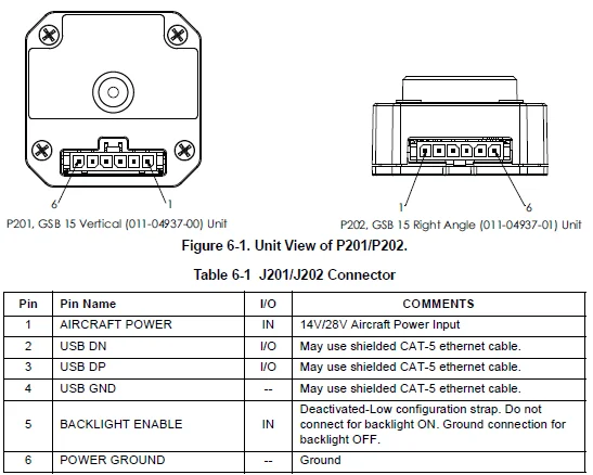
APPENDIX A OUTLINE AND INSTALLATION DRAWINGS
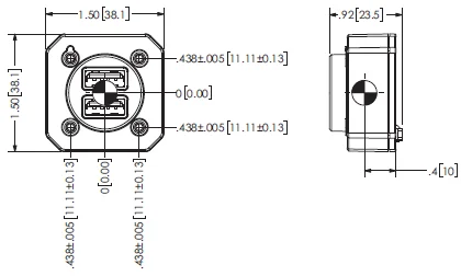
VERTICAL CONNECTOR (-00 CONFIG), UNIT ONLY
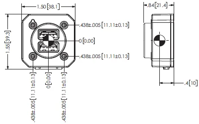
RIGHT-ANGLE CONNECTOR (-00 CONFIG), UNIT ONLY
VERTICAL CONNECTOR (-00 CONFIG), WITH CONNECTOR KIT (011-05044-00)
RIGHT-ANGLE CONNECTOR (-00 CONFIG), WITH CONNECTOR KIT (011-05044-00)
NOTES:
- DIMENSIONS: INCHES[mm]. METRIC VALUES ARE FOR REFERENCE ONLY.
- DIMENSIONS ARE NOMINAL AND TOLERANCES ARE NOT IMPLIED UNLESS SPECIFICALLY STATED.
VERTICAL CONNECTOR (-00 CONFIG) WITH CONNECTOR KIT (011-05044-00)
RIGHT-ANGLE CONNECTOR (-01 CONFIG) WITH CONNECTOR KIT (011-05044-00)

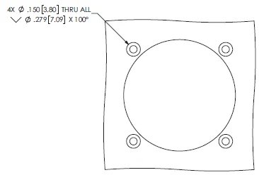
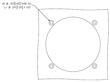
RECOMMENDED PANEL CUTOUT DIMENSIONS FOR UNIT
STANDARD HOLES (FOR PAN HEAD SCREWS)
COUNTERSUNK HOLES (FOR 100° FLAT HEAD SCREWS)
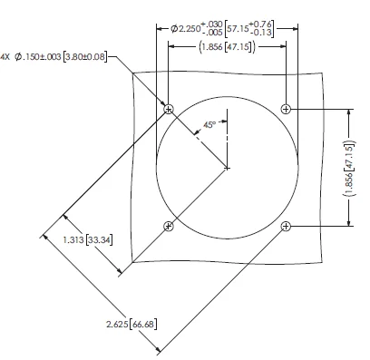
VERTICAL CONNECTOR (-00 CONFIG) WITH 2.25″ MOUNTING KIT (011-05043-00)
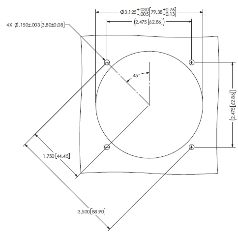
VERTICAL CONNECTOR (-00 CONFIG)WITH 3.125″ MOUNTING KIT (011-05043-01)
011-05043-00 STANDARD HOLES (FOR PAN HEAD SCREWS)
011-05043-01 STANDARD HOLES (FOR PAN HEAD SCREWS)
011-05043-00 COUNTERSUNK HOLES (FOR 100° FLAT HEAD SCREWS)
011-05043-01 COUNTERSUNK HOLES (FOR 100° FLAT HEAD SCREWS)
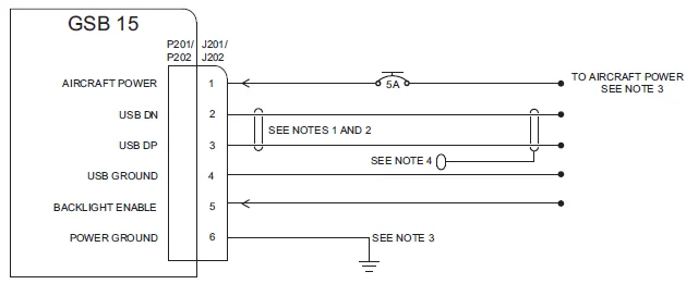
APPENDIX B INTERCONNECT DRAWINGS
NOTES:
- TERMINATE SHIELDING 0.01” [0.0254 cm] FROM CONNECTOR
- USE TWISTED SHIELDED PAIR WIRING, 6 ft MAX.
- USE 22 AWG OR LARGER FOR POWER AND GROUND WIRES, 25 ft MAX.
- RING TERMINAL P/N 235-00117-00
For more Manuals by Garmin, visit ManualsLibraryy
Garmin GSB 15 Dual-Port USB Charging Hub-FAQs
What is the Garmin GSB 15?
The Garmin GSB 15 is a dual-port USB charging hub designed for aviation and vehicle setups. It provides fast, reliable charging for compatible Garmin devices and other electronics.
What size is the Garmin GSB 15 hub?
The GSB 15 measures 1.50” x 1.55” x 0.84” for the right-angle connector and 1.50” x 1.50” x 0.92” for the vertical connector. It’s compact and easy to mount in tight spaces.
What type of charging ports does the GSB 15 have?
It comes with USB Type-A ports supporting Quick Charge™ technology with output options of 5V 3A, 9V 2A, and 12V 1.5A (18W max) per port.
Can I charge my Garmin GPS using the GSB 15 hub?
Yes, you can use a UL-certified power bank or a USB wall adapter to charge your Garmin. Some smartphones even support reverse charging for compatible Garmin devices.
Can I plug my Garmin GPS into a car’s USB port?
Only if the vehicle power cable provided by Garmin supports it. Otherwise, use the Garmin vehicle power cable and adapter to ensure proper operation and charging.
Why doesn’t Garmin use USB-C for all devices?
Garmin avoids USB-C on some models because USB-C ports can be more prone to water ingress, especially for outdoor or aviation environments where durability matters.
Can I charge my Garmin using a USB-C cable?
Yes, if you have a USB-C to Garmin adapter. Plug the adapter into your USB-C cable to charge Garmin watches or devices that don’t have a native USB-C port.
Are USB-A and USB-C the same?
No. USB-A is the traditional rectangular connector, while USB-C is smaller, reversible, and supports faster charging and data speeds.
What certifications does the GSB 15 have?
The Garmin GSB 15 is TSO-C71 certified and features Qualcomm® Quick Charge™ technology, ensuring safe and efficient performance in aviation use.

