
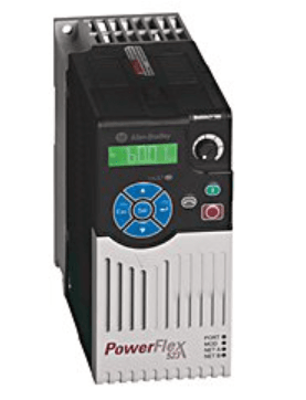
Allen-Bradley PowerFlex 523 AC Drive Programming
General Precautions
ATTENTION: The drive contains high voltage capacitors which take time to discharge after removal of the mains supply. Before working on the drive, ensure isolation of the mains supply from line inputs [R, S, T (L1, L2, L3)]. Wait three minutes for capacitors to discharge to safe voltage levels. Failure to do so may result in personal injury or death. Darkened display LEDs are not an indication that capacitors have discharged to safe voltage levels.
ATTENTION: Only qualified personnel familiar with adjustable frequency AC drives and associated machinery should plan or implement the installation, start-up, and subsequent maintenance of the system. Failure to comply may result in personal injury and/or equipment damage.
ATTENTION: This drive contains ESD (Electrostatic Discharge) sensitive parts and assemblies. Static control precautions are required when installing, testing, servicing, or repairing this assembly. Component damage may result if ESD control procedures are not followed. If you are not familiar with static control procedures, reference A-B publication 8000-4.5.2, “Guarding Against Electrostatic Damage” or any other applicable ESD protection handbook.
ATTENTION: An incorrectly applied or installed drive can result in component damage or a reduction in product life. Wiring or application errors, such as undersizing the motor, incorrect or inadequate AC supply, or excessive ambient temperatures may result in malfunction of the system.
ATTENTION: The bus regulator function is extremely useful for preventing nuisance overvoltage faults resulting from aggressive decelerations, overhauling loads, and eccentric loads. However, it can also cause either of the following two conditions to occur.
- Fast positive changes in input voltage or imbalanced input voltages can cause uncommanded positive speed changes;
- Actual deceleration times can be longer than commanded deceleration times However, a “Stall Fault” is generated if the drive remains in this state for 1 minute. If this condition is unacceptable, the bus regulator must be disabled (see parameter A550 [Bus Reg Enable]). In addition, installing a properly sized dynamic brake resistor will provide equal or better performance in most cases.
ATTENTION: Risk of injury or equipment damage exists. The drive does not contain user-serviceable components. Do not disassemble the drive chassis.
Mounting Considerations
- Mount the drive upright on a flat, vertical, and level surface.
Frame Screw Size Screw Torque A M5 (#10…24) 1.56…1.96 Nm (14…17 lb-in.) B M5 (#10…24) 1.56…1.96 Nm (14…17 lb-in.) C M5 (#10…24) 1.56…1.96 Nm (14…17 lb-in.) D M5 (#10…24) 2.45…2.94 Nm (22…26 lb-in.) E M8 (5/16 in.) 6.0…7.4 Nm (53…65 lb-in.) - Protect the cooling fan by avoiding dust or metallic particles.
- Do not be exposed to a corrosive atmosphere.
- Protect from moisture and direct sunlight.
Minimum Mounting Clearances
See Dimensions and Weight on page 32 for mounting dimensions.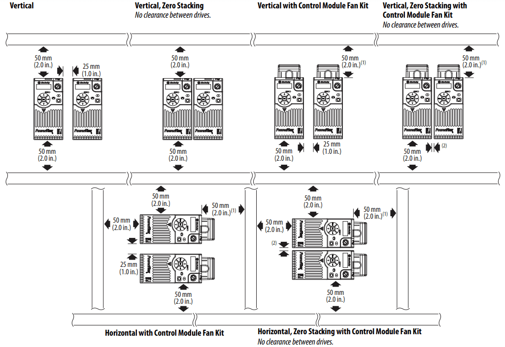
- For Frame E with Control Module Fan Kit only, a clearance of 95 mm (3.7 in.) is required.
- For Frame E with Control Module Fan Kit only, a clearance of 12 mm (0.5 in.) is required.
Ambient Operating Temperatures
See Appendix B of the PowerFlex 520-Series User Manual, publication 520-UM001 for option kits.
|
Mounting |
Enclosure Rating(3) | Ambient Temperature | |||
| Minimum | Maximum (No Derate) | Maximum (Derate)(4) | Maximum with Control Module Fan Kit (Derate)(2) (5) | ||
| Vertical | IP 20/Open Type |
-20 °C (-4 °F) | 50 °C (122 °F) | 60 °C (140 °F) | 70 °C (158 °F) |
| IP 30/NEMA 1/UL Type 1 | 45 °C (113 °F) | 55 °C (131 °F) | – | ||
| Vertical, Zero Stacking | IP 20/Open Type | 45 °C (113 °F) | 55 °C (131 °F) | 65 °C (149 °F) | |
| IP 30/NEMA 1/UL Type 1 | 40 °C (104 °F) | 50 °C (122 °F) | – | ||
| Horizontal with Control Module Fan Kit(1) (2) | IP 20/Open Type | 50 °C (122 °F) | – | 70 °C (158 °F) | |
| Horizontal, Zero Stacking with Control Module Fan Kit(1)(2) | IP 20/Open Type | 45 °C (113 °F) | – | 65 °C (149 °F) | |
- Catalogs 25x-D1P4N104 and 25x-E0P9N104 cannot be mounted using either of the horizontal mounting methods.
- Requires installation of the PowerFlex 520-Series Control Module Fan Kit, catalog number 25-FANx-70C.
- IP 30/NEMA 1/UL Type 1 rating requires installation of the PowerFlex 520-Series IP 30/NEMA 1/UL Type 1 option kit, catalog number 25-JBAx.
- For catalogs 25x-D1P4N104 and 25x-E0P9N104, the temperature is listed under the Max. (Derate) column is reduced by 5 °C (9 °F) for all mounting methods.
- For catalogs 25x-D1P4N104 and 25x-E0P9N104, the temperature listed under the Max. with Control Module Fan Kit (Derate) column is reduced by 10 °C (18 °F) for vertical and vertical with zero stacking mounting methods only.
General Grounding Requirements
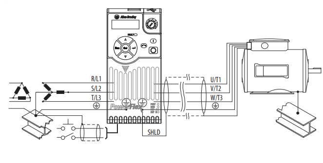
The drive Safety Ground – (PE) must be connected to the system ground. Ground impedance must conform to the requirements of national and local industrial safety regulations and/or electrical codes. The integrity of all ground connections should be periodically checked.
Typical Grounding
Ungrounded Distribution Systems
Disconnecting MOVs
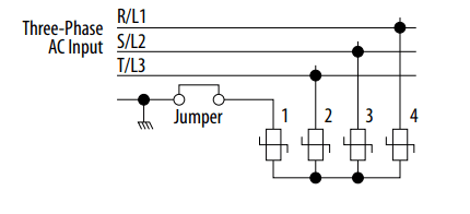
To prevent drive damage, the MOVs connected to ground shall be disconnected if the drive is installed on an ungrounded distribution system (IT mains) where the line-to-ground voltages on any phase could exceed 125% of the nominal line-toline voltage. To disconnect these devices, remove the jumper shown in the diagrams below.
- Turn the screw counterclockwise to loosen.
- Pull the jumper completely out of the drive chassis.
- Tighten the screw to keep it in place.
Jumper Location (Typical)
Power Module
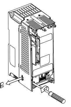
IMPORTANT: Tighten screw after jumper removal.
Phase to Ground MOV Removal
CE Conformity
See the PowerFlex 520-Series Adjustable Frequency AC Drive User Manual, publication 520-UM001 for details on how to comply with the Low Voltage (LV) and Electromagnetic Compatibility (EMC) Directives.
Fuses and Circuit Breakers
| Catalog No.(1) | Output Ratings | Input Ratings | Branch Circuit Protection | Min. Enclosure | IP 20 Open Type Watts Loss | |||||||||
| PowerFlex 523 | PowerFlex 525 | Normal Duty | Heavy Duty | Amps | Voltage Range |
kVA | Max Amps(2) | Fuse Ratings Min/Max |
Contactors | 140M Motor Protectors (3) (4) (5) | ||||
| HP | kW | HP | kW | |||||||||||
100…120V AC (-15%, +10%) – 1-Phase Input, 0…230V 3-Phase Output
| 25A-V1P6N104 | – | 0.25 | 0.2 | 0.25 | 0.2 | 1.6 | 85…132 | 0.8 | 6.4 | 10/16 | 100-C09 | 140M-C2E-B63 | – | 20.0 |
| 25A-V2P5N104 | 25B-V2P5N104 | 0.5 | 0.4 | 0.5 | 0.4 | 2.5 | 85…132 | 1.3 | 9.6 | 16/20 | 100-C12 | 140M-C2E-C10 | – | 27.0 |
| 25A-V4P8N104 | 25B-V4P8N104 | 1.0 | 0.75 | 1.0 | 0.75 | 4.8 | 85…132 | 2.5 | 19.2 | 25/40 | 100-C23 | 140M-D8E-C20 | – | 53.0 |
| 25A-V6P0N104 | 25B-V6P0N104 | 1.5 | 1.1 | 1.5 | 1.1 | 6.0 | 85…132 | 3.2 | 24.0 | 32/50 | 100-C23 | 140M-F8E-C25 | – | 67.0 |
200…240V AC (-15%, +10%) – 1-Phase Input, 0…230V 3-Phase Output
| 25A-A1P6N104 | – | 0.25 | 0.2 | 0.25 | 0.2 | 1.6 | 170…264 | 1.4 | 5.3 | 6/10 | 100-C09 | 140M-C2E-B63 | – | 20.0 |
| 25A-A2P5N104 | 25B-A2P5N104 | 0.5 | 0.4 | 0.5 | 0.4 | 2.5 | 170…264 | 1.7 | 6.5 | 10/16 | 100-C09 | 140M-C2E-C10 | – | 29.0 |
| 25A-A4P8N104 | 25B-A4P8N104 | 1.0 | 0.75 | 1.0 | 0.75 | 4.8 | 170…264 | 2.8 | 10.7 | 16/25 | 100-C12 | 140M-C2E-C16 | – | 50.0 |
| 25A-A8P0N104 | 25B-A8P0N104 | 2.0 | 1.5 | 2.0 | 1.5 | 8.0 | 170…264 | 4.8 | 18.0 | 25/40 | 100-C23 | 140M-F8E-C25 | – | 81.0 |
| 25A-A011N104 | 25B-A011N104 | 3.0 | 2.2 | 3.0 | 2.2 | 11.0 | 170…264 | 6.0 | 22.9 | 32/50 | 100-C37 | 140M-F8E-C25 | – | 111.0 |
200…240V AC (-15%, +10%) – 1-Phase Input with EMC Filter, 0…230V 3-Phase Output
| 25A-A1P6N114 | – | 0.25 | 0.2 | 0.25 | 0.2 | 1.6 | 170…264 | 1.4 | 5.3 | 6/10 | 100-C09 | 140M-C2E-B63 | – | 20.0 |
| 25A-A2P5N114 | 25B-A2P5N114 | 0.5 | 0.4 | 0.5 | 0.4 | 2.5 | 170…264 | 1.7 | 6.5 | 10/16 | 100-C09 | 140M-C2E-C10 | – | 29.0 |
| 25A-A4P8N114 | 25B-A4P8N114 | 1.0 | 0.75 | 1.0 | 0.75 | 4.8 | 170…264 | 2.8 | 10.7 | 16/25 | 100-C12 | 140M-C2E-C16 | – | 53.0 |
| 25A-A8P0N114 | 25B-A8P0N114 | 2.0 | 1.5 | 2.0 | 1.5 | 8.0 | 170…264 | 4.8 | 18.0 | 25/40 | 100-C23 | 140M-F8E-C25 | – | 84.0 |
| 25A-A011N114 | 25B-A011N114 | 3.0 | 2.2 | 3.0 | 2.2 | 11.0 | 170…264 | 6.0 | 22.9 | 32/50 | 100-C37 | 140M-F8E-C25 | – | 116.0 |
200…240V AC (-15%, +10%) – 3-Phase Input, 0…230V 3-Phase Output
| 25A-B1P6N104 | – | 0.25 | 0.2 | 0.25 | 0.2 | 1.6 | 170…264 | 0.9 | 1.9 | 3/6 | 100-C09 | 140M-C2E-B25 | – | 20.0 |
| 25A-B2P5N104 | 25B-B2P5N104 | 0.5 | 0.4 | 0.5 | 0.4 | 2.5 | 170…264 | 1.2 | 2.7 | 6/6 | 100-C09 | 140M-C2E-B40 | – | 29.0 |
| 25A-B5P0N104 | 25B-B5P0N104 | 1.0 | 0.75 | 1.0 | 0.75 | 5.0 | 170…264 | 2.7 | 5.8 | 10/16 | 100-C09 | 140M-C2E-B63 | – | 50.0 |
| 25A-B8P0N104 | 25B-B8P0N104 | 2.0 | 1.5 | 2.0 | 1.5 | 8.0 | 170…264 | 4.3 | 9.5 | 16/20 | 100-C12 | 140M-C2E-C10 | – | 79.0 |
| 25A-B011N104 | 25B-B011N104 | 3.0 | 2.2 | 3.0 | 2.2 | 11.0 | 170…264 | 6.3 | 13.8 | 20/32 | 100-C23 | 140M-C2E-C16 | – | 107.0 |
| 25A-B017N104 | 25B-B017N104 | 5.0 | 4.0 | 5.0 | 4.0 | 17.5 | 170…264 | 9.6 | 21.1 | 32/45 | 100-C23 | 140M-F8E-C25 | – | 148.0 |
| 25A-B024N104 | 25B-B024N104 | 7.5 | 5.5 | 7.5 | 5.5 | 24.0 | 170…264 | 12.2 | 26.6 | 35/63 | 100-C37 | 140M-F8E-C32 | – | 259.0 |
| 25A-B032N104 | 25B-B032N104 | 10.0 | 7.5 | 10.0 | 7.5 | 32.2 | 170…264 | 15.9 | 34.8 | 45/70 | 100-C43 | 140M-F8E-C45 | – | 323.0 |
| 25A-B048N104 | 25B-B048N104 | 15.0 | 11.0 | 10.0 | 7.5 | 48.3 | 170…264 | 20.1 | 44.0 | 63/90 | 100-C60 | 140M-F8E-C45 | 1416.0(7) | 584.0 |
| 25A-B062N104 | 25B-B062N104 | 20.0 | 15.0 | 15.0 | 11.0 | 62.1 | 170…264 | 25.6 | 56.0 | 70/125 | 100-C72 | – | – | 708.0 |
380…480V AC (-15%, +10%) – 3-Phase Input, 0…460V 3-Phase Output
| 25A-D1P4N104 | 25B-D1P4N104 | 0.5 | 0.4 | 0.5 | 0.4 | 1.4 | 323…528 | 1.7 | 1.9 | 3/6 | 100-C09 | 140M-C2E-B25 | – | 27.0 |
| 25A-D2P3N104 | 25B-D2P3N104 | 1.0 | 0.75 | 1.0 | 0.75 | 2.3 | 323…528 | 2.9 | 3.2 | 6/10 | 100-C09 | 140M-C2E-B40 | – | 37.0 |
| 25A-D4P0N104 | 25B-D4P0N104 | 2.0 | 1.5 | 2.0 | 1.5 | 4.0 | 323…528 | 5.2 | 5.7 | 10/16 | 100-C09 | 140M-C2E-B63 | – | 80.0 |
| 25A-D6P0N104 | 25B-D6P0N104 | 3.0 | 2.2 | 3.0 | 2.2 | 6.0 | 323…528 | 6.9 | 7.5 | 10/16 | 100-C09 | 140M-C2E-C10 | – | 86.0 |
| 25A-D010N104 | 25B-D010N104 | 5.0 | 4.0 | 5.0 | 4.0 | 10.5 | 323…528 | 12.6 | 13.8 | 20/32 | 100-C23 | 140M-C2E-C16 | – | 129.0 |
| 25A-D013N104 | 25B-D010N104 | 7.5 | 5.5 | 7.5 | 5.5 | 13.0 | 323…528 | 14.1 | 15.4 | 20/35 | 100-C23 | 140M-D8E-C20 | – | 170.0 |
| 25A-D017N104 | 25B-D017N104 | 10.0 | 7.5 | 10.0 | 7.5 | 17.0 | 323…528 | 16.8 | 18.4 | 25/40 | 100-C23 | 140M-D8E-C20 | – | 221.0 |
| 25A-D024N104 | 25B-D024N104 | 10.0 | 7.5 | 10.0 | 7.5 | 17.0 | 323…528 | 24.1 | 26.4 | 35/63 | 100-C37 | 140M-F8E-C32 | 656.7(7) | 221.0 |
| 25A-D030N104 | 25B-D030N104 | 20.0 | 15.0 | 15.0 | 11.0 | 30.0 | 323…528 | 30.2 | 33.0 | 45/70 | 100-C43 | 140M-F8E-C45 | 656.7(7) | 387.0 |
380…480V AC (-15%, +10%) – 3-Phase Input with EMC Filter, 0…460V 3-Phase Output
| 25A-D1P4N114 | 25B-D1P4N114 | 0.5 | 0.4 | 0.5 | 0.4 | 1.4 | 323…528 | 1.7 | 1.9 | 3/6 | 100-C09 | 140M-C2E-B25 | – | 27.0 |
| 25A-D2P3N114 | 25B-D2P3N114 | 1.0 | 0.75 | 1.0 | 0.75 | 2.3 | 323…528 | 2.9 | 3.2 | 6/10 | 100-C09 | 140M-C2E-B40 | – | 37.0 |
| 25A-D4P0N114 | 25B-D4P0N114 | 2.0 | 1.5 | 2.0 | 1.5 | 4.0 | 323…528 | 5.2 | 5.7 | 10/16 | 100-C09 | 140M-C2E-B63 | – | 81.0 |
| 25A-D6P0N114 | 25B-D6P0N114 | 3.0 | 2.2 | 3.0 | 2.2 | 6.0 | 323…528 | 6.9 | 7.5 | 10/16 | 100-C09 | 140M-C2E-C10 | – | 88.0 |
| 25A-D010N114 | 25B-D010N114 | 5.0 | 4.0 | 5.0 | 4.0 | 10.5 | 323…528 | 12.6 | 13.8 | 20/32 | 100-C23 | 140M-C2E-C16 | – | 133.0 |
| Catalog No.(1) | Output Ratings | Input Ratings | Branch Circuit Protection | Min. Enclosure | IP 20 Open Type Watts Loss | |||||||||
| PowerFlex 523 | PowerFlex 525 | Normal Duty | Heavy Duty | Amps | Voltage Range |
kVA | Max Amps(2) | Fuse Ratings Min/Max |
Contactors | 140M Motor Protectors (3) (4) (5) | ||||
| HP | kW | HP | kW | |||||||||||
| 25A-D013N114 | 25B-D013N114 | 7.5 | 5.5 | 7.5 | 5.5 | 13.0 | 323…528 | 14.1 | 15.4 | 20/35 | 100-C23 | 140M-D8E-C20 | – | 175.0 |
| 25A-D017N114 | 25B-D017N114 | 10.0 | 7.5 | 10.0 | 7.5 | 17.0 | 323…528 | 16.8 | 18.4 | 25/40 | 100-C23 | 140M-D8E-C20 | – | 230.0 |
| 25A-D024N114 | 25B-D024N114 | 15.0 | 11.0 | 15.0 | 11.0 | 24.0 | 323…528 | 24.1 | 26.4 | 35/63 | 100-C37 | 140M-F8E-C32 | 656.7(7) | 313.0 |
| 25A-D030N114 | 25B-D030N114 | 20.0 | 15.0 | 15.0 | 11.0 | 30.0 | 323…528 | 30.2 | 33.0 | 45/70 | 100-C43 | 140M-F8E-C45 | 656.7(7) | 402.0 |
| 25A-D037N114 | 25B-D037N114 | 25.0 | 18.5 | 20.0 | 15.0 | 37.0 | 323…528 | 30.8 | 33.7 | 45/70 | 100-C43 | 140M-F8E-C45 | – | 602.0 |
| 25A-D043N114 | 25B-D043N114 | 30.0 | 22.0 | 25.0 | 18.5 | 43.0 | 323…528 | 35.6 | 38.9 | 50/80 | 100-C60 | 140M-F8E-C45 | – | 697.0 |
525…600V AC (-15%, +10%) – 3-Phase Input, 0…575V 3-Phase Output
| 25A-E0P9N104 | 25B-E0P9N104 | 0.5 | 0.4 | 0.5 | 0.4 | 0.9 | 446…660 | 1.4 | 1.2 | 3/6 | 100-C09 | 140M-C2E-B25 | – | 22.0 |
| 25A-E1P7N104 | 25B-E1P7N104 | 1.0 | 0.75 | 1.0 | 0.75 | 1.7 | 446…660 | 2.6 | 2.3 | 3/6 | 100-C09 | 140M-C2E-B25 | – | 32.0 |
| 25A-E3P0N104 | 25B-E3P0N104 | 2.0 | 1.5 | 2.0 | 1.5 | 3.0 | 446…660 | 4.3 | 3.8 | 6/10 | 100-C09 | 140M-C2E-B40 | – | 50.0 |
| 25A-E4P2N104 | 25B-E4P2N104 | 3.0 | 2.2 | 3.0 | 2.2 | 4.2 | 446…660 | 6.1 | 5.3 | 10/16 | 100-C09 | 140M-D8E-B63 | – | 65.0 |
| 25A-E6P6N104 | 25B-E6P6N104 | 5.0 | 4.0 | 5.0 | 4.0 | 6.6 | 446…660 | 9.1 | 8.0 | 10/20 | 100-C09 | 140M-D8E-C10 | – | 95.0 |
| 25A-E9P9N104 | 25B-E9P9N104 | 7.5 | 5.5 | 7.5 | 5.5 | 9.9 | 446…660 | 12.8 | 11.2 | 16/25 | 100-C16 | 140M-D8E-C16(6) | – | 138.0 |
| 25A-E012N104 | 25B-E012N104 | 10.0 | 7.5 | 10.0 | 7.5 | 12.0 | 446…660 | 15.4 | 13.5 | 20/32 | 100-C23 | 140M-D8E-C16 | – | 164.0 |
| 25A-E019N104 | 25B-E019N104 | 15.0 | 11.0 | 15.0 | 11.0 | 19.0 | 446…660 | 27.4 | 24.0 | 32/50 | 100-C30 | 140M-F8E-C25 | 656.7(7) | 290.0 |
| 25A-E022N104 | 25B-E022N104 | 20.0 | 15.0 | 15.0 | 11.0 | 22.0 | 446…660 | 31.2 | 27.3 | 35/63 | 100-C30 | 140M-F8E-C32 | 656.7(7) | 336.0 |
| 25A-E027N104 | 25B-E027N104 | 25.0 | 18.5 | 20.0 | 15.0 | 27.0 | 446…660 | 28.2 | 24.7 | 35/50 | 100-C30 | 140M-F8E-C32 | 1416.0(7) | 466.0 |
| 25A-E032N104 | 25B-E032N104 | 30.0 | 22.0 | 25.0 | 18.5 | 32.0 | 446…660 | 33.4 | 29.2 | 40/63 | 100-C37 | 140M-F8E-C32 | 1416.0(7) | 562.0 |
- Normal Duty (ND) and Heavy Duty (HD) ratings are available for this drive.
- When the drive is controlling motors with lower amp ratings, refer to the drive nameplate for drive input current rating.
- The AIC ratings of the Bulletin 140M Motor Protector Circuit Breakers may vary. See Bulletin 140M Motor Protection Circuit Breakers Application Ratings.
- Bulletin 140M with adjustable current range should have the current trip set to the minimum range that the device will not trip.
- Manual Self-Protected (Type E) Combination Motor Controller, UL listed for 480Y/277 and 600Y/347 AC input. Not UL listed for use on 480V or 600V Delta/Delta, corner ground, or high resistance ground systems.
- When used with the 140M circuit breaker, the 25A-E9P9104 must be installed in a ventilated or non-ventilated enclosure with a minimum size of 457.2 x 457.2 x 269.8 mm (18 x 18 x 10.62 in.).
- When using a Manual Self-Protected (Type E) Combination Motor Controller with this drive power rating, the drive must be installed in a ventilated or non-ventilated enclosure with the minimum volume specified in this column. Application-specific thermal considerations may require a larger enclosure.
Power Wiring
Recommended Shielded Wire
| Location | Rating/Type | Description |
| Standard (Option 1) | 600V, 90 °C (194 °F) XHHW2/RHW-2 Anixter B209500-B209507, Belden 29501-29507, or equivalent | • Four tinned copper conductors with XLPE insulation. • Copper braid/aluminum foil combination shield and tinned copper drain wire. • PVC jacket. |
| Standard (Option 2) | Tray rated 600V, 90 °C (194 °F) RHH/RHW-2 Anixter OLF-7xxxxx or equivalent | • Three tinned copper conductors with XLPE insulation. • 5 mil single helical copper tape (25% overlap min.) with three bare copper grounds in contact with the shield. • PVC jacket. |
| Class I & II; Division I & II | Tray rated 600V, 90 °C (194 °F) RHH/RHW-2 Anixter 7V-7xxxx-3G or equivalent | • Three bare copper conductors with XLPE insulation and impervious corrugated continuously welded aluminum armor. • Black sunlight resistant PVC jacket overall. • Three copper grounds on #10 AWG and smaller. |
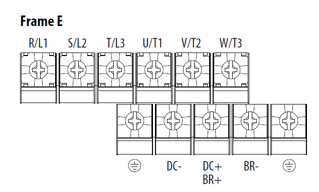
Power Terminal Block Diagrams and Wiring Specifications
| Terminal | Description |
| R/L1, S/L2 | 1-Phase Input Line Voltage Connection |
| R/L1, S/L2, T/L3 | 3-Phase Input Line Voltage Connection |
| U/T1, V/T2, W/T3 | Motor Phase Switch any two motor leads to change Connection = |
| DC+, DC- | DC Bus Connection (except for 110V 1-Phase) |
| BR+, BR- | Dynamic Brake Resistor Connection |
| | Safety Ground – PE |
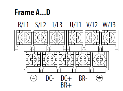
| Frame | Maximum Wire Size(1) | Minimum Wire Size(1) | Torque |
| A | 5.3 mm2 (10 AWG) | 0.8 mm2 (18 AWG) | 1.76…2.16 Nm (15.6. 19.1 lb-in.) |
| B | 8.4 mm2 (8 AWG) | 2.1 mm2 (14 AWG) | 1.76…2.16 Nm (15.6. 19.1 lb-in.) |
| C | 8.4 mm2 (8 AWG) | 2.1 mm2 (14 AWG) | 1.76…2.16 Nm (15.6. 19.1 lb-in.) |
| D | 13.3 mm2 (6 AWG) | 5.3 mm2 (10 AWG) | 1.76…2.16 Nm (15.6. 19.1 lb-in.) |
| E | 26.7 mm2 (3 AWG) | 8.4 mm2 (8 AWG) | 3.09…3.77 Nm (27.3. 33.4 lb-in.) |
Input Power Conditions
| Input Power Condition | Corrective Action |
| Low Line Impedance (less than 1% line reactance) | • Install Line Reactor(2) • or Isolation Transformer |
| Greater than 120 kVA supply transformer | |
| Line has power factor correction capacitors | • Install Line Reactor(2) • or Isolation Transformer |
| Line has frequent power interruptions | |
| Line has intermittent noise spikes in excess of 6000V (lightning) | |
| Phase to ground voltage exceeds 125% of normal line to line voltage | • Remove MOV jumper to ground. • or Install Isolation Transformer with grounded secondary if necessary. |
| Ungrounded distribution system | |
| 240V open delta configuration (stinger leg)(1) | Install Line Reactor(2) |
- For drives applied on an open delta with a middle phase grounded neutral system, the phase opposite the phase that is tapped in the middle to the neutral or earth is referred to as the “stinger leg,” “high leg,” “red leg,” etc. This leg should be identified throughout the system with red or orange tape on the wire at each connection point. The stinger leg should be connected to the center Phase B on the reactor.
- See Appendix B of the PowerFlex 520-Series Adjustable Frequency AC Drive User Manual, publication 520-UM001 for accessory ordering information.
I/O Wiring
Recommended Signal Wire
| Signal Type/ Where Used | Belden Wire Type (or equivalent)(1) | Description | Minimum Insulation Rating |
| Analog I/O & PTC | 8760/9460 | 0.750 mm2 (18 AWG), twisted pair, 100% shield with drain(2) | 300V, 60 °C (140 °F) |
| Remote Pot | 8770 | 0.750 mm2 (18 AWG), 3 conductors, shielded | |
| Encoder/Pulse I/O | 9728/9730 | 0.196 mm2 (24 AWG), individually shielded pairs |
- Stranded or solid wire.
- If the wires are short and contained within a cabinet that has no sensitive circuits, the use of shielded wire may not be necessary but is always recommended.
Recommended Control Wire for Digital I/O
| Type | Wire Type(s) | Description | Minimum Insulation Rating |
| Unshielded | Per US NEC or applicable national or local code | – | 300V, 60 °C (140 °F) |
| Unshielded | Multi-conductor shielded cable such as Belden 8770 (or equivalent) | 0.750 mm2 (18 AWG), 3 conductor, shielded. |
Control I/O Terminal Block Wire Specifications
| Frame | Maximum Wire Size(1) | Minimum Wire Size(1) | Torque |
| A…E | 1.3 mm2 (16 AWG) | 1.3 mm2 (16 AWG) | 0.71…0.86 Nm (6.2. 7.6 lb-in.) |
- Maximum/minimum sizes that the terminal block will accept – these are not recommendations.
See the PowerFlex 520-Series Adjustable Frequency AC Drive User Manual, publication 520-UM001 for recommendations on maximum power and control cable length.
Control Terminal Block
PowerFlex 523 Control I/O Wiring Block Diagram
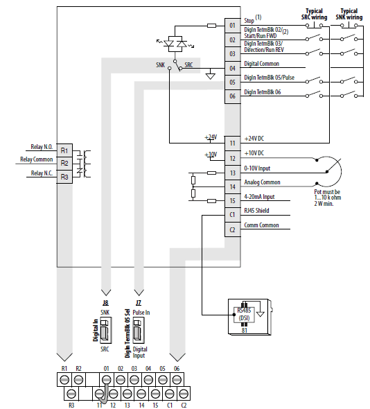
- IMPORTANT I/O Terminal 01 is always a stop input. The stopping mode is determined by the drive setting. The drive is shipped with a jumper installed between I/O Terminals 01 and 11. Remove this jumper when using I/O Terminal 01 as a stop or enable input.
PowerFlex 523 Control I/O Terminal Designations
| No. | Signal | Default | Description | Parameter |
| R1 | Relay N.O. | Fault | Normally open contact for output relay. | t076 |
| R2 | Relay Common | Fault | Common for output relay. | t081 |
| R3 | Relay N.C. | Motor Running | Normally closed contact for output relay. | P045 |
| 01 | Stop | Coast | Three wire stop. However, it functions as a stop under all input modes and cannot be disabled. | P045, P046, P048, P050, A544, t062 |
| 02 | DigIn TermBlk 02/ Start/Run FWD | Run FWD | Used to initiate motion and also can be used as a programmable digital input. It can be programmed with t062 [DigIn TermBlk 02] as three wire (Start/Dir with Stop) or two wire (Run FWD/Run REV) control. Current consumption is 6 mA. | t063 |
| 03 | DigIn TermBlk 03/ Dir/Run REV | Run REV | Used to initiate motion and also can be used as a programmable digital input. It can be programmed with t063 [DigIn TermBlk 03] as three wire (Start/Dir with Stop) or two wire (Run FWD/Run REV) control. Current consumption is 6 mA. | t063 |
| 04 | Digital Common | – | Return for digital I/O. Electrically isolated (along with the digital I/O) from the rest of the drive. | – |
| 05 | DigIn TermBlk 05/ Pulse In | Preset Freq | Program with t065 [DigIn TermBlk 05]. Also functions as a Pulse Train input for reference or speed feedback. The maximum frequency is 100 kHz. Current consumption is 6 mA. | t065 |
| 06 | DigIn TermBlk 06 | Preset Freq | Program with t066 [DigIn TermBlk 06]. Current consumption is 6 mA. | t066 |
| 11 | +24V DC | – | Referenced to Digital Common. Drive supplied power for digital inputs. Maximum output current is 100 mA. | – |
| 12 | +10V DC | – | Referenced to Analog Common. Drive supplied power for 0…10V external potentiometer. Maximum output current is 15 mA. | P047, P049 |
| 13 | 0-10V In(1) | Not Active | For external 0-10V (unipolar) input supply or potentiometer wiper. Input impedance: Voltage source = 100 kW Allowable potentiometer resistance range = 1…10 kW | P047, P049, t062, t063, t065, t066, t093, A459, A471 |
| 14 | Analog Common | – | Return for the analog I/O. Electrically isolated (along with the analog I/O) from the rest of the drive. | – |
| 15 | 4-20mA In(1) | Not Active | For external 4-20 mA input supply. Input impedance = 250 W | P047, P049, t062, t063, t065, t066, A459, A471 |
| C1 | C1 | – | This terminal is tied to the RJ-45 port shield. Tie this terminal to a clean ground in order to improve noise immunity when using external communication peripherals. | – |
| C2 | C2 | – | This is the signal common for the communication signals. | – |
PowerFlex 525 Control I/O Wiring Block Diagram PowerFlex 525 Control I/O Terminal Designations
| No. | Signal | Default | Description | Parameter |
| R1 | Relay 1 N.O. | Fault | Normally open contact for output relay. | t076 |
| R2 | Relay 1 Common | Fault | Common for output relay. | |
| R5 | Relay 2 Common | Motor Running | Common for output relay. | t081 |
| R6 | Relay 2 N.C. | Motor Running | Normally closed contact for output relay. | |
| 01 | Stop | Coast | Three wire stop. However, it functions as a stop under all input modes and cannot be disabled. | P045 |
| 02 | DigIn TermBlk 02/ Start/Run FWD | Run FWD | Used to initiate motion and also can be used as a programmable digital input. It can be programmed with t062 [DigIn TermBlk 02] as three wire (Start/Dir with Stop) or two wire (Run FWD/Run REV) control. Current consumption is 6 mA. | P045, P046, P048, P050, A544, t062 |
| 03 | DigIn TermBlk 03/ Dir/Run REV | Run REV | Used to initiate motion and also can be used as a programmable digital input. It can be programmed with t062 [DigIn TermBlk 02] as three wire (Start/Dir with Stop) or two wire (Run FWD/Run REV) control. Current consumption is 6 mA. | t063 |
| 04 | Digital Common | – | Return for digital I/O. Electrically isolated (along with the digital I/O) from the rest of the drive. | – |
| 05 | DigIn TermBlk 05 | –Preset Freq | Program with t065 [DigIn TermBlk 05]. Current consumption is 6 mA. | t065 |
| 06 | DigIn TermBlk 06 | –Preset Freq | Program with t066 [DigIn TermBlk 06]. Current consumption is 6 mA. | t066 |
| 07 | DigIn TermBlk 07/ Pulse In | Start Source 2 + Speed Reference2 | Program with t067 [DigIn TermBlk 07]. Also functions as a Pulse Train input for reference or speed feedback. The maximum frequency is 100 kHz. Current consumption is 6 mA. | t067 |
| 08 | DigIn TermBlk 08 | Jog Forward | Program with t068 [DigIn TermBlk 08]. Current consumption is 6 mA. | t068 |
| C1 | C1 | – | This terminal is tied to the RJ-45 port shield. Tie this terminal to a clean ground in order to improve noise immunity when using external communication peripherals. | – |
| C2 | C2 | – | This is the signal common for the communication signals. | – |
| S1 | Safety 1 | – | Safety input 1. Current consumption is 6 mA. | – |
| S2 | Safety 2 | – | Safety input 2. Current consumption is 6 mA. | – |
| S+ | Safety +24V | – | +24V supply for safety circuit. Internally tied to the +24V DC source (Pin 11). | – |
| 11 | +24V DC | – | Referenced to Digital Common. Drive supplied power for digital inputs. Maximum output current is 100 mA. | – |
| 12 | +10V DC | – | Referenced to Analog Common. Drive supplied power for 0…10V external potentiometer. Maximum output current is 15 mA. | P047, P049 |
| 13 | ±10V In | Not Active | For external 0-10V (unipolar) or ±10V (bipolar) input supply or potentiometer wiper. Input impedance: Voltage source = 100 kW Allowable potentiometer resistance range = 1…10 kW | P047, P049, t062, t063, t065, t066, t093, A459, A471 |
| 14 | Analog Common | – | Return for the analog I/O. Electrically isolated (along with the analog I/O) from the rest of the drive. | – |
| 15 | 4-20mA In | Not Active | For external 4-20 mA input supply. Input impedance = 250 W | P047, P049, t062, t063, t065, t066, A459, A471 |
| 16 | Analog Output | OutFreq 0-10 | The default analog output is 0-10V. To convert a current value, change the Analog Output jumper to 0-20 mA. Program with t088 [Analog Out Sel]. Maximum analog value can be scaled with t089 [Analog Out High]. Maximum Load: 4-20 mA = 525 W (10.5V) 0-10V = 1 kW (10 mA) | t088, t089 |
| 17 | Opto Output 1 | Motor Running | Program with t069 [Opto Out1 Sel]. Each Opto-Output is rated 30V DC 50 mA (Non-inductive). | t069, t070, t075 |
| 18 | Opto Output 2 | At Frequency | Program with t072 [Opto Out1 Sel]. Each Opto-Output is rated 30V DC 50 mA (Non-inductive). | t072, t073, t075 |
| 19 | Opto Common | – | The emitters of the Optocoupler Outputs (1 and 2) are tied together at Optocoupler Common. Electrically isolated from the rest of the drive. | – |
Basic Display Group Parameters
See the PowerFlex 520-Series Adjustable Frequency AC Drive User Manual, publication 520-UM001 for detailed descriptions of the parameters listed here, as well as the full list of available parameters.
| No. | Parameter | Min/Max | Display/Options |
| b001 | [Output Freq] | 0.00/[Maximum Freq] | 0.01 Hz |
| Output frequency present at T1, T2 & T3 (U, V & W). Does not include slip frequency. | |||
| b002 | [Commanded Freq] | 0.00/[Maximum Freq] | 0.01 Hz |
| Value of the active frequency command even if the drive is not running. Important: The frequency command can come from a number of sources. | |||
| b003 | [Output Current] | 0.00/(Drive Rated Amps x 2) | 0.01 A |
| Output current present at T1, T2 & T3 (U, V & W). | |||
| b004 | [Output Voltage] | 0.0/Drive Rated Volts | 0.1V |
| Output voltage present at T1, T2 & T3 (U, V & W). | |||
| b005 | [DC Bus Voltage] | 0/1200VDC | 1VDC |
| Filtered DC bus voltage level of the drive. | |||
| b006 | [Drive Status] | 00000/11111 | Digit 5 Digit 4 Digit 3 Digit 2 Digit 1 SafetyActive(1) Decelerating Accelerating Forward Running |
| Present operating condition of the drive. (1) Setting is specific to PowerFlex 525 drives only. | |||
| b007, b008, b009 | [Fault x Code] | F0/F127 | F0 |
| A code that represents a drive fault. Codes appear in these parameters in the order they occur (b007 [Fault 1 Code] = the most recent fault). Repetitive faults are only recorded once. See Fault and Diagnostic Group for more information. | |||
| b010 | [Process Display] | 0/9999 | 1 |
| Output frequency scaled by [Process Disp Hi] and [Process Disp Lo]. | |||
| b0012 | [Control Source] | 0000/2165 | Digit 4, 3, & 2 Digit 1 Freq Command Source Start Command Source |
| Active source of the Start Command and Frequency Command. Normally defined by the settings of P046, P048, P050 [Start Source x] and P047, P049, P051 [Speed Referencex]. | |||
| b013 | [Contrl In Status] | 0000/1111 | Digit 4 Digit 3 Digit 2 Digit 1 DB Trans On(1) DigIn TBlk 3 DigIn TBlk 2 DigIn TBlk 1 |
| State of the digital terminal blocks 1…3 and DB transistor. Important: Actual control commands may come from a source other than the control terminal block. (1) Setting is specific to PowerFlex 525 drives only. | |||
| b014 | [Dig In Status] | 0000/1111 | Digit 4 Digit 3 Digit 2 Digit 1 DigIn TBlk 8(1) DigIn TBlk 7(1)DigIn TBlk 6 DigIn TBlk 5 |
| State of the programmable digital inputs. (1) Setting is specific to PowerFlex 525 drives only. | |||
| b015 | [Output RPM] | 0/24000 rpm | 1 rpm |
| Current output frequency in rpm. Scale is based on P035 [Motor NP Poles]. | |||
| b016 | [Output Speed] | 0.0/100.0% | 0.1% |
| Current output frequency in %. Scale is 0% at 0.00 Hz to 100% at P044 [Maximum Freq]. | |||
| b017 | [Output Power] | 0.00/(Drive Rated Power x 2) | 0.01 kW |
| Output power present at T1, T2 & T3 (U, V & W). | |||
| b018 | [Power Saved] | 0.00/655.35 kW | 0.01 kW |
| Instantaneous power savings of using this drive compared to an across the line starter. | |||
| b019 | [Elapsed Run time] | 0/65535 x 10 hr | 1 = 10 hr |
| Accumulated time drive is outputting power. Time is displayed in 10 hour increments. | |||
| b020 | [Average Power] | 0.00/(Drive Rated Power x 2) | 0.01 kW |
| Average power used by the motor since the last reset of the meters. | |||
| b021 | [Elapsed kWh] | 0.0/100.0 kWh | |
| Accumulated output energy of the drive. When the maximum value of this parameter is reached, it resets to zero and b022 [Elapsed MWh] is incremented.0.1 kWh | |||
| No. | Parameter | Min/Max | Display/Options |
| b022 | [Elapsed MWh] | 0.0/6553.5 MWh | 0.1 MWh |
| Accumulated output energy of the drive. | |||
| b023 | [Energy Saved] | 0.0/6553.5 kWh | 0.1 kWh |
| Total energy savings of using this drive compared to an across the line starter since the last reset of the meters. | |||
| b024 | [Accum kWh Sav] | 0.0/6553.5 kWh | 0.1 = 10 kWh |
| Total approximate accumulated energy savings of the drive compared to using an across the line starter. | |||
| b025 | [Accum Cost Sav] | 0.0/6553.5 | 0.1 |
| Total approximate accumulated cost savings of the drive compared to using an across the line starter. [Accum Cost Sav] = [Average kWh cost] x [Accum kWh Sav] | |||
| b026 | [Accum CO2 Sav] | 0.0/6553.5 kg | 0.1 kg |
| Total approximate accumulated CO2 savings of the drive compared to using an across the line starter. | |||
| b027 | [Drive Temp] | 0/120 °C | 1 °C |
| Present operating temperature of the drive heatsink (inside module). | |||
| b028 | [Control Temp] | 0/120 °C | 1 °C |
| Present operating temperature of the drive control. | |||
| b029 | [Control SW Ver] | 0.000/65.535 | 0.001 |
| Current drive firmware version. | |||
Fault Codes
| No. | Fault | Action |
| F000 | No Fault | – |
| F002 | Auxiliary Input | • Check remote wiring. • Verify communications programming for intentional fault. |
| F003 | Power Loss | • Monitor the incoming AC line for low voltage or line power interruption. • Check input fuses. • Reduce load. |
| F004 | UnderVoltage | Monitor the incoming AC line for low voltage or line power interruption. |
| F005 | OverVoltage | Monitor the AC line for high line voltage or transient conditions. Bus overvoltage can also be caused by motor regeneration. Extend the decel time or install dynamic brake option. |
| F006 | Motor Stalled | • Increase P041, A442, A444, A446 [Accel Time x] or reduce load so drive output current does not exceed the current set by parameter A484, A485 [Current Limit x] for too long. • Check for overhauling load. |
| F007 | Motor Overload | • An excessive motor load exists. Reduce load so drive output current does not exceed the current set by parameter P033 [Motor OL Current]. • Verify A530 [Boost Select] setting. |
| F008 | Heatsink OvrTmp | • Check for blocked or dirty heat sink fins. Verify that ambient temperature has not exceeded the rated ambient temperature. • Check fan. |
| F009 | CC OvrTmp | • Check product ambient temperature. • Check for airflow obstruction. • Check for dirt or debris. • Check fan. |
| F012 | HW OverCurrent | Check programming. Check for excess load, improper A530 [Boost Select] setting, DC brake volts set too high or other causes of excess current. |
| F013 | Ground Fault | Check the motor and external wiring to the drive output terminals for a grounded condition. |
| F015(1) | Load Loss | • Verify connections between motor and load. • Verify level and time requirements. |
| F021 | Output Ph Loss | • Verify motor wiring. • Verify motor. |
| F029 | Analog In Loss | • Check for broken/loose connections at inputs. • Check parameters. |
| No. | Fault | Action |
| F033 | Auto Rstrt Tries | Correct the cause of the fault and manually clear. |
| F038 | Phase U to Gnd | • Check the wiring between the drive and motor. • Check motor for grounded phase. • Replace drive if fault cannot be cleared. |
| F039 | Phase V to Gnd | |
| F040 | Phase W to Gnd | |
| F041 | Phase UV Short | • Check the motor and drive output terminal wiring for a shorted condition. • Replace drive if fault cannot be cleared. |
| F042 | Phase UW Short | |
| F043 | Phase VW Short | |
| F048 | Params Defaulted | • Clear the fault or cycle power to the drive. • Program the drive parameters as needed. |
| F059(1) | Safety Open | Check safety input signals. If not using safety, verify and tighten jumper for I/O terminals S1, S2 and S+. |
| F063 | SW OverCurrent | • Verify connections between motor and load. • Verify level and time requirements. |
| F064 | Drive Overload | Reduce load or extend Accel Time. |
| F070 | Power Unit | • Check maximum ambient temperature has not been exceeded. • Cycle power. • Replace drive if fault cannot be cleared. |
| F071 | DSI Net Loss | • Cycle power. • Check communications cabling. • Check Modbus or DSI setting. • Check Modbus or DSI status. |
| F072 | Opt Net Loss | • Cycle power. • Check communications cabling. • Check network adapter setting. • Check external network status. |
| F073(1) | EN Net Loss | • Cycle power. • Check communications cabling. • Check EtherNet/IP setting. • Check external network status. |
| F080 | Autotune Failure | Restart procedure. |
| F081 | DSI Comm Loss | • Cycle power. • Check communications cabling. • Check Modbus or DSI setting. • Check Modbus or DSI status. • Modify using C125 [Comm Loss Action]. • Connecting I/O terminals C1 and C2 to ground may improve noise immunity. • Replace wiring, Modbus master device, or control module. |
| F082 | Opt Comm Loss | • Cycle power. • Reinstall option card in drive. • Modify using C125 [Comm Loss Action]. • Replace wiring, port expander, option card, or control module. |
| F083(1) | EN Comm Loss | • Cycle power. • Check EtherNet/IP setting. • Check drive’s Ethernet settings and diagnostic parameters. • Modify using C125 [Comm Loss Action]. • Replace wiring, Ethernet switch, or control module. |
| F091(1) | Encoder Loss | • Check Wiring. • If P047, P049, P051 [Speed Referencex] = 16 “Positioning” and A535 [Motor Fdbk Type] = 5 “Quad Check”, swap the Encoder channel inputs or swap any two motor leads. • Replace encoder. |
| F094 | Function Loss | Close input to the terminal and cycle power. |
| F100 | Parameter Chksum | Set P053 [Reset To Defalts] to 2 “Factory Rset”. |
| F101 | External Storage | Set P053 [Reset To Defalts] to 2 “Factory Rset”. |
| F105 | C Connect Err | Clear fault and verify all parameter settings. Do not remove or install the control module while power is applied. |
| F106 | Incompat C-P | • Change to a different power module. • Change to a PowerFlex 523 control module. |
| F107 | Replaced C-P | • Change to a different power module. • Replace control module if changing power module does not work. |
| No. | Fault | Action |
| F109 | Mismatch C-P | Set P053 [Reset To Defalts] to 3 “Power Reset”. |
| F110 | Keypad Membrane | • Cycle power. • Replace control module if fault cannot be cleared. |
| F111(1) | Safety Hardware | • Check safety input signals. If not using safety, verify and tighten jumper for I/O terminals S1, S2 and S+. • Replace control module if fault cannot be cleared. |
| F114 | uC Failure | • Cycle power. • Replace control module if fault cannot be cleared. |
| F122 | I/O Board Fail | • Cycle power. • Replace drive or control module if fault cannot be cleared. |
| F125 | Flash Update Req | Perform a firmware flash update operation to attempt to load a valid set of firmware. |
| F126 | NonRecoverablErr | • Clear fault or cycle power to the drive. • Replace drive or control module if fault cannot be cleared. |
| F127 | DSIFlashUpdatReq | Perform a firmware flash update operation using DSI communications to attempt to load a valid set of firmware. |
(1) This fault is not applicable to PowerFlex 523 drives.
Drive Ratings
PowerFlex 523 Frames – Ratings are in kW and (HP).
| Frame | 1-Phase 100…120V | 1-Phase 200…240V | 1-Phase 200…240V w/ Filter | 3-Phase 200…240V | 3-Phase 380…480V | 3-Phase 380…480V w/ Filter | 3-Phase 525…600V |
| A | 0.2…0.4 (0.25…0.5) | 0.2…0.75 (0.25…1.0) | 0.2…0.75 (0.25…1.0) | 0.2…2.2 (0.25…3.0) | 0.4…2.2 (0.5…3.0) | 0.4…2.2 (0.5…3.0) | 0.4…2.2 (0.5…3.0) |
| B | 0.75…1.1 (1.0…1.5) | 1.5…2.2 (2.0…3.0) | 1.5…2.2 (2.0…3.0) | 4.0 (5.0) | 4.0 (5.0) | 4.0 (5.0) | 4.0 (5.0) |
| C | – | – | – | 5.5 (7.5) | 5.5…7.5 (7.5…10.0) | 5.5…7.5 (7.5…10.0) | 5.5…7.5 (7.5…10.0) |
| D | – | – | – | 7.5 (10.0) | 11.0…15.0 (15.0…20.0) | 11.0…15.0 (15.0…20.0) | 11.0…15.0 (15.0…20.0) |
| E | – | – | – | 11.0…15.0 (15.0…20.0) | – | 18.5…22.0 (25.0…30.0) | 18.5…22.0 (25.0…30.0) |
PowerFlex 525 Frames – Ratings are in kW and (HP).
| Frame | 1-Phase 100…120V | 1-Phase 200…240V | 1-Phase 200…240V w/ Filter | 3-Phase 200…240V | 3-Phase 380…480V | 3-Phase 380…480V w/ Filter | 3-Phase 525…600V |
| A | 0.4 (0.5) | 0.4…0.75 (0.5…1.0) | 0.4…0.75 (0.5…1.0) | 0.4…2.2 (0.5…3.0) | 0.4…2.2 (0.5…3.0) | 0.4…2.2 (0.5…3.0) | 0.4…2.2 (0.5…3.0) |
| B | 0.75…1.1 (1.0…1.5) | 1.5…2.2 (2.0…3.0) | 1.5…2.2 (2.0…3.0) | 4.0 (5.0) | 4.0 (5.0) | 4.0 (5.0) | 4.0 (5.0) |
| C | – | – | – | 5.5 (7.5) | 5.5…7.5 (7.5…10.0) | 5.5…7.5 (7.5…10.0) | 5.5…7.5 (7.5…10.0) |
| D | – | – | – | 7.5 (10.0) | 11.0…15.0 (15.0…20.0) | 11.0…15.0 (15.0…20.0) | 11.0…15.0 (15.0…20.0) |
| E | – | – | – | 11.0…15.0 (15.0…20.0) | – | 18.5…22.0 (25.0…30.0) | 18.5…22.0 (25.0…30.0) |
Dimensions and Weight
IP 20/Open Type – Dimensions are in mm and (in.). Weights are in kg and (lb).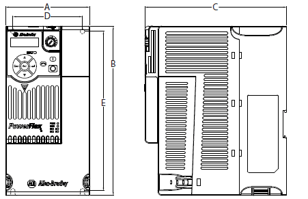
| Frame Size | A | B | C | D | E | Weight |
| A | 72.0 (2.83) | 152.0 (5.98) | 172.0 (6.77) | 57.5 (2.26) | 140.0 (5.51) | 1.1 (2.4) |
| B | 87.0 (3.43) | 180.0 (7.09) | 172.0 (6.77) | 72.5 (2.85) | 168.0 (6.61) | 1.6 (3.5) |
| C | 109.0 (4.29) | 220.0 (8.66) | 184.0 (7.24) | 90.5 (3.56) | 207.0 (8.15) | 2.3 (5.0) |
| D | 130.0 (5.12) | 260.0 (10.24) | 212.0 (8.35) | 116.0 (4.57) | 247.0 (9.72) | 3.9 (8.6) |
| E | 185.0 (7.28) | 300.0 (11.81) | 279.0 (10.98) | 160.0 (6.30) | 280.0 (11.02) | 12.9 (28.4) |
EMC Line Filter – Dimensions are in mm and (in.).
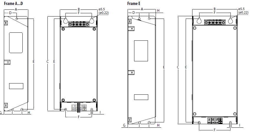

| Frame Size(1) | A | B | C | D | E | F | G | H | I |
| A | 55.0 (2.17) | 72.0 (2.83) | 234.0 (9.21) | 30.0 (1.18) | 223.0 (8.78) | 54.0 (2.13) | 20.0 (0.79) | 23.0 (0.91) | 5.5 (0.22) |
| B | 70.0 (2.76) | 87.0 (3.43) | 270.0 (10.63) | 35.0 (1.38) | 258.0 (10.16) | 58.0 (2.28) | 25.0 (0.98) | 24.0 (0.94) | 5.5 (0.22) |
| C | 70.0 (2.76) | 109.0 (4.29) | 275.0 (10.83) | 37.0 (1.46) | 263.0 (10.35) | 76.0 (2.99) | 25.0 (0.98) | 28.0 (1.10) | 5.5 (0.22) |
| D | 80.0 (3.15) | 130.0 (5.12) | 310.0 (12.20) | 33.0 (1.30) | 298.0 (11.73) | 90.0 (3.54) | 33.0 (1.30) | 28.0 (1.10) | 5.5 (0.22) |
| E | 80.0 (3.15) | 155.0 (6.10) | 390.0 (15.35) | 33.0 (1.30) | 375.0 (14.76) | 110.0 (4.33) | 33.0 (1.30) | 28.0 (1.10) | 5.5 (0.22) |
Important Information
Solid-state equipment has operational characteristics differing from those of electromechanical equipment. Safety
Guidelines for the Application, Installation and Maintenance of Solid State Controls (publication SGI-1.1 available from your local Rockwell Automation sales office or online at http://www.rockwellautomation.com/literature/) describes some important differences between solid-state equipment and hard-wired electromechanical devices. Because of this difference, and also because of the wide variety of uses for solid-state equipment, all persons responsible for applying this equipment must satisfy themselves that each intended application of this equipment is acceptable.
In no event will Rockwell Automation, Inc. be responsible or liable for indirect or consequential damages resulting from the use or application of this equipment. The examples and diagrams in this publication are included solely for illustrative purposes. Because of the many variables and requirements associated with any particular installation, Rockwell Automation, Inc. cannot assume responsibility or liability for actual use based on the examples and diagrams.
No patent liability is assumed by Rockwell Automation, Inc. with respect to use of information, circuits, equipment, or software described in this manual.
Reproduction of the contents of this manual, in whole or in part, without written permission of Rockwell Automation, Inc., is prohibited.
Documentation Feedback
Your comments will help us serve your documentation needs better. If you have any suggestions on how to improve this document, complete this form, publication RA-DU002, available at http://www.rockwellautomation.com/literature/.
For more manuals by Allen-Bradley, visit ManualsLibraryy
Allen-Bradley PowerFlex 523 AC Drive Programming-FAQs
What is the operating voltage range for PowerFlex 523?
The PowerFlex 523 supports global voltage classes from 100 to 600 Volts AC, with an input frequency tolerance of 47 to 63 Hz.
What is the voltage tolerance for the PowerFlex 523?
The voltage tolerance is –10% of the minimum and +10% of the maximum. The frequency tolerance is 47–63 Hz.
What does F013 fault on PowerFlex 523 mean?
The F013 fault indicates a ground fault. This can occur if Parameter P039 [Torque Perf Mode] is set to 1 [SVC] and the drive was not autotuned.
How do I clear a fault on a VFD?
To clear a fault, address the root cause first. Then reset the VFD by either cycling the power or pressing the reset button. Monitor the VFD afterward to ensure normal operation.
What are the main components of the PowerFlex system?
The PowerFlex system consists of three main components:
1. Storage Data Server (SDS)
2. Storage Data Client (SDC)
3. Meta Data Manager (MDM)
Version 3.5 introduces a new component called the Storage Data Replicator (SDR).
What modes does PowerFlex Manager support?
PowerFlex Manager can be deployed in three modes:
1. Alerting Mode
2. Managed Mode (requires a license)
3. Lifecycle Mode
How does a VFD control motor speed?
A VFD converts fixed AC power to DC power using a rectifier, smooths it in the DC bus, and then converts it back to AC power at the desired frequency using an inverter. By adjusting the frequency of the AC power, the VFD controls motor speed.
What is the maximum frequency setting for PowerFlex 525?
The default maximum frequency for the PowerFlex 525 is 60 Hz.
What does fault 105 on PowerFlex 523 indicate?
Fault F105 [C Connect Err] or F114 [uC Failure] can suggest excessive common mode noise in the cabinet. Updating to Firmware Revision 7.001 or addressing cabinet noise issues can resolve this fault.

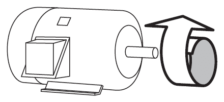 forward direction.