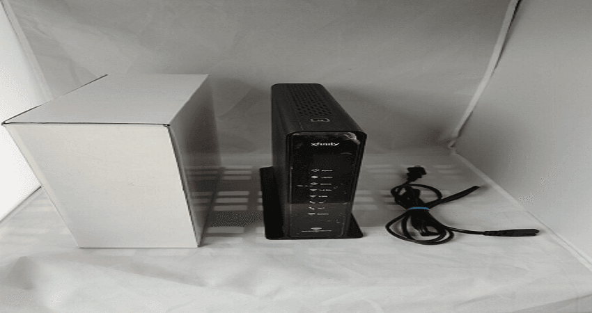
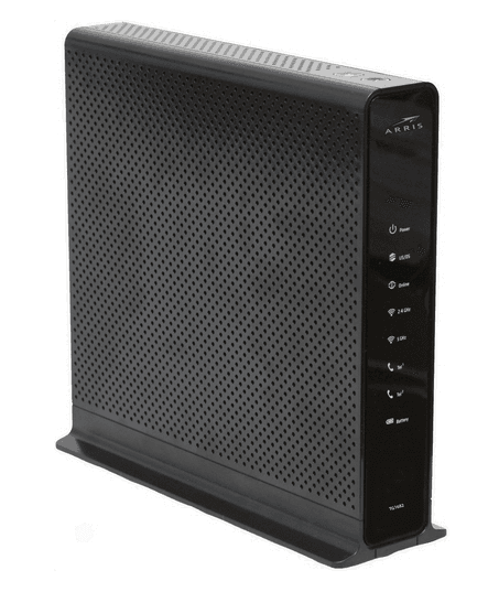
Arris Touchstone TG1682G Wireless Internet Modem
Battery Installation and Removal
Introduction
The TG1682G Telephony Gateway supports a Lithium-Ion backup battery to provide continued telephone service during power outages. The battery backup is not intended to take the place of AC power.
The TG1682G supports the following battery models:
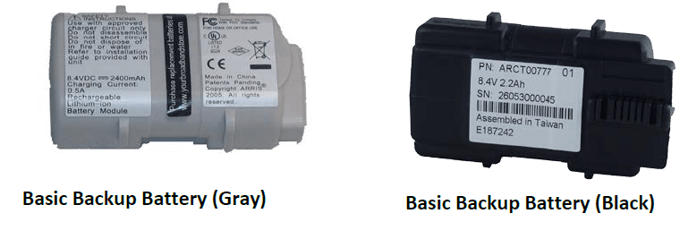
- Basic backup battery: provides up to 4 hours of backup time, depending on your Telephony Gateway model and usage. It may be light gray or black.

- Extended backup battery: provides up to 8 hours of backup time, depending on model and usage. It has a strap between the battery guides. This is the standard battery for the TG1682G.

Basic Battery Installation and Replacement
This model of the Telephony Gateway can provide continued telephone service during power outages. The battery backup is not intended to take the place of AC power.
Use this procedure to install and replace the backup battery.
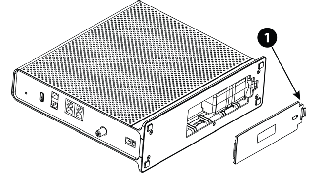
- Press down and pull back on the latch holding the battery door (on the bottom of the Telephony Gateway). Pull the door toward you. Set the door aside in a safe place.

- 1. Latch End
- 2. Hold the battery pack so that the guides on the battery align with the slots on the Telephony Gateway and slide the battery into the bay.
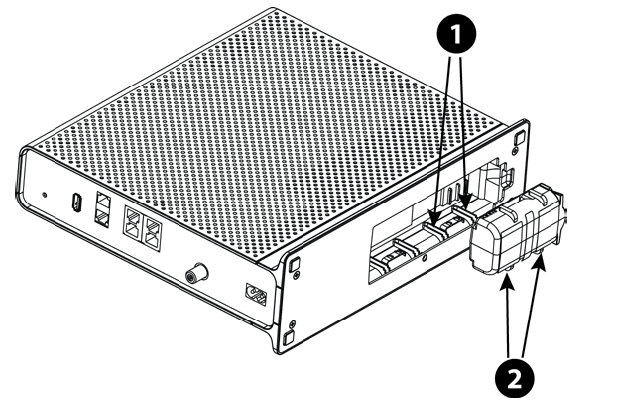
- Battery Slots
- Battery Guides
- Push the battery pack into the bay until it sits in place. If you are taking the battery out of the Telephony Gateway, position your finger in the battery opening area and use leverage to dislodge the battery while pulling it straight back.
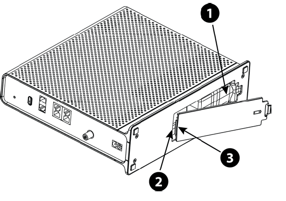
- Replace the door. To do so, place the hinge tabs of the battery door into the receiver slots inside the Telephony Gateway battery compartment on the opposite end of the battery opening. Rotate the door toward the unit until the latch snaps back into place.

- 1. Battery Compartment
- 2. Receiver Slot
- 3. Hinge Tab
Extended Battery Installation and Replacement
This model of the Telephony Gateway can provide continued telephone service during power outages. The battery backup is not intended to take the place of AC power. Use this procedure to install or replace the backup battery.
Press down and pull back on the latch holding the battery door (on the bottom of the Telephony Gateway). Pull the door toward you. Set the door aside in a safe place.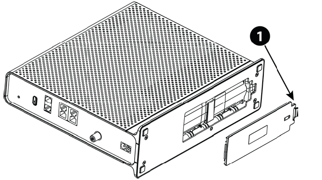
- Latch End
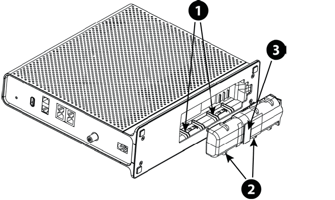
- Hold the battery pack so that the guides on the battery align with the slots on the Telephony Gateway and slide the battery into the bay.

- 1. Battery Slots
- 2. Battery Guides
- 3. Battery Pull Strap
- Push the battery pack into the bay until it latches into place. If you are taking the battery out of the Telephony Gateway, use the battery pull strap to dislodge the battery.
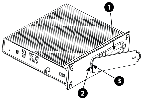
- Replace the door. To do so, place the tabs of the battery door into the slot inside the Telephony Gateway battery compartment. Rotate the door toward the front of the Telephony Gateway until the latch snaps back into place.

- 1. Battery Compartment
- 2. Receiver Slot
- 3. Hinge Tab
Battery Usage and Storage Conditions
- The life expectancy of your battery should be several years, provided that it was purchased from an approved source.
- Your battery goes through a calibration procedure when it is first installed or replaced. This procedure can take up to 72 hours to complete and is repeated every six months.
- If your battery becomes fully drained during a power outage, the calibration procedure will need to be repeated.
- Your battery should be installed in your Telephony Gateway and kept there at all times. Do not store the battery separately from the Telephony Gateway for any prolonged period.
Front Panel
The front of the Telephony Gateway has the following indicators.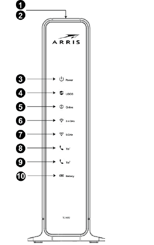
- WPS Button/LED: begins associating the Telephony Gateway with a wireless device. LED indicates Wireless Protected Setup (WPS) is active.
- DECT Button/LED: pages all of the registered handsets. Press again to cancel the paging. Press and hold the button for 15 seconds to place the unit in registration mode for handset registration.
- Power: indicates whether AC power is available to the unit.
- US/DS: indicates upstream/downstream connectivity.
- Online: indicates internet data transmission status.
- 2.4 GHz: indicates the status of the 2.4 GHz wireless LAN.
- 5 GHz: indicates the status of the 5 GHz wireless LAN.
- Tel 1: indicates the status of telephone line 1.
- Tel 2: indicates the status of telephone line 2.
- Battery: indicates the battery status.
Rear Panel
The rear of the Telephony Gateway has the following connectors and controls.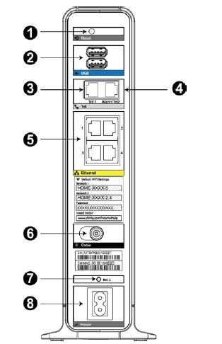
- Reset button: resets the Telephony Gateway as if you power cycled the unit. Use a pointed non-metallic object to press this button.
- USB: USB host connector – future support for external USB devices
- Tel 1: connector for the first phone line.
- Tel 2: a connector for the second phone line.
- Ethernet (1 – 4): connectors for use with a computer LAN port.
- Cable: a connector for the coaxial cable.
- MoCA: indicates connectivity between the Telephony Gateway and other home devices connected via the MoCA network.
- Power: a connector for the power cord.
Desktop Mounting Instructions
Position the Telephony Gateway so that:
- it stands vertically on its base (Do not lay it flat on its side.)
- air flows freely around it
- the back faces the nearest wall
- it will not fall to the floor if bumped or moved
- the ventilation holes on the sides of the unit are not blocked
Factors Affecting Wireless Range
Several factors can affect the usable range for wireless connections.
| Increases range | n Raising the unit above the devices (for example, installing the Telephony Gateway on the upper floor of a multi-story dwelling) n Adding a wireless extender to the network |
| Decreases range | n Lowering the unit below the devices (for example, installing the Telephony Gateway in a basement) n Metal or concrete walls between the Telephony Gateway and other devices n Large metal appliances, aquariums, or metal cabinets between the Telephony Gateway and other devices n Interference and RF noise (2.4 GHz wireless phones, microwave ovens, or other wireless networks) |
Connecting the Telephony Gateway
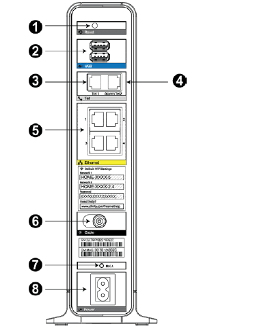
- Connect one end of the coax cable to the cable outlet or splitter, and the other end to the Telephony Gateway’s Cable connector (6). Tighten the connections by hand, then tighten an additional 1/8 turn with a wrench.
- Insert the plug from the power cord into the Power connector on the back of the Telephony Gateway (8) and insert the power cord into a convenient AC outlet. The Power light on the front of the Telephony Gateway lights up, then flashes once (refer to the LED tables shown in Using the Telephony Gateway (page 31)). See Troubleshooting (page 38) if the Power light does not turn on.
- Connect one end of the Ethernet cable to any Ethernet port on the back of the Telephony Gateway, (5) and the other end to the Ethernet port on a computer, hub, or broadband router.
- Connect one end of the telephone cable to the telephone port on the back of the Telephony Gateway (3 or 4). Connect the other end to the telephone.
Configuring Your Wireless Connection
The TG1682G ships with wireless LAN security set by default. See the security label on your product for the factory security settings.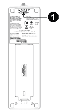
- Security Label
If you need to modify the Telephony Gateway’s default wireless security settings, or if you want to configure any other wireless LAN settings, refer to the following instructions.
Configuring Your Ethernet Connection
If your computer is equipped with a LAN card providing an Ethernet connection, you may have to configure your computer’s TCP/IP settings. The steps that follow will guide you through setting your computer’s TCP/IP settings to work with the Telephony Gateway.
Requirements
Make sure you have the following before attempting to configure your Ethernet connection:
- Computer with Ethernet interface
- Ethernet cable (supplied)
- IP address, subnet, gateway, and DNS information for installations not using DHCP
TCP/IP Configuration for Mac OS X
Follow these steps to configure the Ethernet interface on a Mac OS X operating system.
- Open System Preferences, either by choosing System Preferences from the Apple menu or by clicking the System Preferences icon in the dock.
- Click the Network icon.
- Choose Automatic from the Location drop-down menu, and Built-in Ethernet from the Show menu.
- Choose the TCP/IP tab, if necessary. If you are using TCP/IPv4, go to step 5. If your cable provider requires TCP/IPv6, go to step 8.
- Choose Using DHCP from the Configure IPv4 menu.
- If necessary, click the Renew DHCP Lease button.
- Close the System Properties application. TCP/IPv4 configuration is completed.
- If you are using TCP/IPv6, click Configure IPv6 near the bottom of the previous window.
- Choose Automatically from the Configure IPv6 drop-down menu and click OK.
- Close the System Properties application.
Setting up Your Computer to Use the Telephony Gateway
Follow the instructions in the information packet supplied by your service provider. Contact your service provider if you need help setting up your computer.
Indicator Lights for the TG1682G
The Telephony Gateway has LED indicator lights to assist in troubleshooting.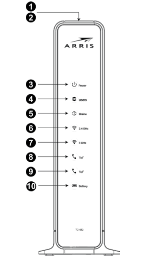
- WPS Button/LED
- DECT Button/LED
- Power
- US/DS
- Online
- 2.4 GHz Wi-Fi
- 5 GHz Wi-Fi
- Tel 1
- Tel 2
- Battery
Wiring Problems
If the Telephony Gateway begins flashing all its lights for more than 10 seconds, this indicates a problem with the telephone wiring — the red and green wires may be shorted (touching), or there may be undesired voltage on the lines. If this pattern persists for more than 10 seconds, disconnect the telephone lines from the Telephony Gateway, then call a wiring technician for assistance.
| Mode | Ethernet (LEDs on rear panel connector) | 2.4G Wi-Fi / 5G Wi- Fi | Tel 1 / Tel 2 | MoCA |
| AC Power | Green LED On = Computer with 1Gbps port connected
Amber LED On = Computer with 100 Mbps/10Mbps port connected
Amber/Green LED Flash = Computer activity
Both LEDs Off = Computer not connected | On = Wi-Fi enabled
Flash = Computer activity
Off = Wi-Fi disabled | On = On-hook Flash = Off-hook Off = disabled | On = MoCA enabled and MoCA network device attached
Flash = MoCA network device activity/traffic
Off = MoCA disabled or no MoCA network device attached |
| No AC Power | Off | Off | On = On-hook Flash = Off-hook Off = disabled | Off |
| Firmware Upgrade | (normal operation) | (normal operation) | (normal operation) | (normal operation) |
Patterns: Normal Operation (WAN and Battery)
The following table shows light patterns during normal operation.
| Mode | Power | US/DS | Online | Battery |
| AC Power Good | On | On = Connected to the Internet | On = Internet available | On = Battery good or low |
| Flash = Not connected to the Internet | Off = Internet not available | Off = Battery missing | ||
| Flash = Battery bad |
| Mode | Power | US/DS | Online | Battery |
| No AC Power, | Flash | Off | Off | Off = Battery |
| Battery Installed | power | |||
| Flash = Battery | ||||
| bad | ||||
| No AC Power, No Battery | Off | Off | Off | Off |
| Firmware Upgrade | On | Flash | On | (normal operation) |
Patterns: Startup Sequence
The following tables show the Telephony Gateway light patterns during each phase of the startup sequence. There are two phases of startup; the telephony phase and the cable modem phase. Both are outlined below.
Telephony Startup Sequence
| Power, US/DS, Online | Telephone 1 | Telephone 2 | Battery | Description |
| Off | Off | Off | Off | No power to the modem |
| Flash | Flash | Flash | Flash | Power-on Self Test |
| See Cable Modem Startup-Sequence (page 34) | ||||
| On | Flash | Off | Off | Retrieving telephone network information |
| On | Off | Flash | Off | Retrieving telephone line information |
| On | Flash | Flash | Off | Activating telephone service |
| Normal Operation | ||||
Cable Modem Startup Sequence
| US/DS | Online | Description |
| Slow Flash (1/second) | Off | Downstream acquisition in progress |
| On (until Upstream acquisition starts) | Off | Downstream acquisition completed |
| Fast Flash (3/second) | Off | Upstream acquisition in progress |
| On | Slow Flash (during acquisition)
On (when modem IP address obtained) | Upstream acquisition completed, ready for service |
Using the Reset Button
Use the Reset button (1), on the back of the Telephony Gateway, to reset the modem and perform initialization as if you power cycled the unit. You may need to reset the Telephony Gateway if you are having problems connecting to the Internet. Using this button will be rare.
Use a pointed non-metallic object to press this button. The Reset button is recessed to prevent accidental resets.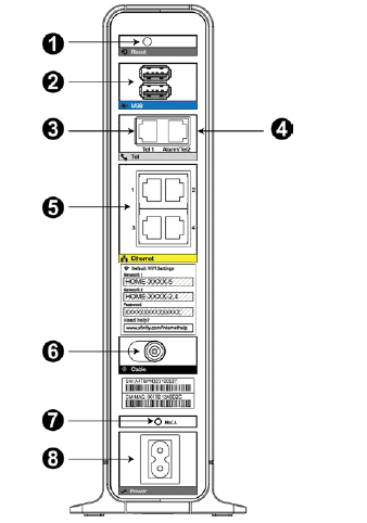
- Reset button
- USB
- Tel 1
- Tel 2
- Ethernet (1 – 4)
- Cable
- MoCA
- Power
Resetting the Router to Factory Defaults
To reset the router to factory defaults, press and hold the Reset button on the back of the Telephony Gateway for more than fifteen seconds. This restores the wireless setup configuration and router configuration parameters to the factory defaults. You may need to do this if a misconfiguration has locked out all access.
Booting from Battery
The TG1682G supports a “Boot from Battery” feature that allows the Telephony Gateway to provide continued telephone service during power outages.
Troubleshooting
The Telephony Gateway is plugged in, but the Power light is Off Check all power connections. Is the power cord plugged in firmly at both ends? If you plugged the power cord into a power strip, make sure the strip is switched on. Try to plug the power cord into a different outlet. If the outlet is controlled by a wall switch, make sure the switch is on. Finally, check the fuse or circuit breaker panel.
I’m not getting on the Internet (all connections)
It may take over 30 minutes to establish a connection the first time you power up your Telephony Gateway, especially when many people are online. Always leave your Telephony Gateway plugged into AC power and connected to the cable system.
Check the front panel lights
- The Power and Online lights should be on.
- If the Power light blinks for more than 30 minutes, call your service provider for assistance.
Check your cable connections. Connectors should be tight. The coax cable should not be pinched, kinked, or bent sharply—any of these can cause a break or short in the cable (you may have to replace the cable). If you have one or more splitters between the Telephony Gateway and CATV outlet, remove the splitters and connect the Telephony Gateway directly to the outlet. Proceed to the Ethernet or wireless solutions if necessary.
For more manuals by Arris visit, ManualsLibraryy
Arris Touchstone TG1682G Wireless Internet Modem-FAQs
What is the Arris TG1682G device?
The Arris TG1682G is a DOCSIS 3.0 modem with 24×8 channel bonding. Once connected to the network, it will show that the device is online and fully operational via indicator lights for Power, Receive, Send, and Online.
What is the IP address for Arris TG1682G?
The default IP address for the Arris TG1682G is 192.168.0.1.
What is the default password for Arris TG1682G?
The default login credentials are:
1. Username: admin
2. Password: password
How can I see what devices are connected to my Arris modem?
Open the ARRIS home screen, tap on the Devices icon in the Status section. The Network Map will display a list of all connected devices.
How do I access the Arris modem’s IP address?
In your web browser (e.g., Google Chrome, Firefox), type 192.168.0.1 in the URL bar and press Enter. You’ll be directed to the login page.
How do I reset the Arris TG1682G modem?
To reset the modem to factory defaults, press and hold the recessed reset button on the back for 30 seconds. After that, the default username (admin) and password (password) will work.
How many devices can connect to the Xfinity gateway?
You can register up to 10 devices on your account to access Xfinity Wi-Fi hotspots.
What is the default admin password for Arris?
The default admin password is password. To log in, use the username admin and the password password unless you’ve changed it.

