Bil-Jax ESP-19 Electric Man-Lift Aerial
GENERAL DESCRIPTION
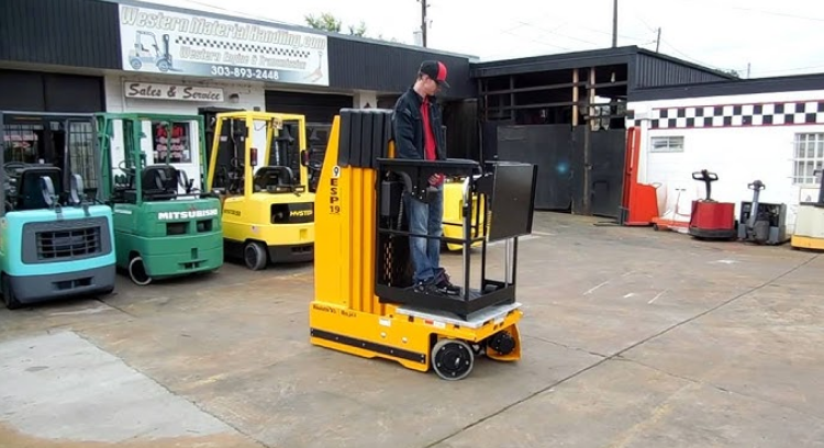
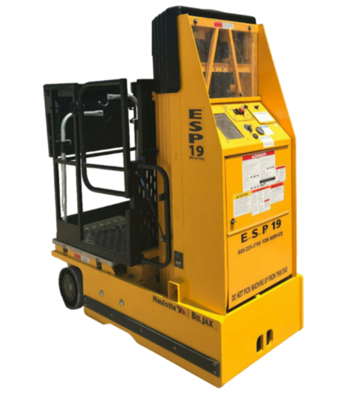
The ESP 19 hydraulic lift is designed and manufactured for use as a warehouse stocking and order picking vehicle. Its guard rail design permits the operator to ride on the platform with the load while transferring parts to and from multiple overhead storage locations. The maximum platform load is limited to 450 lbs. All ESP 19 operations are powered by a 24-Volt DC battery package. A 40-amp battery charger and plug-in receptacle are included in the system for recharging the batteries at the end of each work period. A charge level indicator displays the battery charge status.
The platform lift function is hydraulic, including a hydraulic cylinder, reservoir, and pump. The hydraulic pump motor is driven by a 24-Volt DC electric motor. Elevation is by a 1-3/4 inch linear-displacement hydraulic cylinder and four telescoping mast sections. The lower mast section is raised by a hydraulic cylinder. The upper mast sections are raised mechanically by connecting sets of chains and sheaves (pulleys). The lift platform rises four inches for each inch of hydraulic cylinder extension. Other electrically powered functions include a two-wheel drive transaxle for floor travel and pushbutton steering.
The maximum travel speed is enabled only when the lift platform is down. When the platform is raised, the travel speed is limited. The transaxle includes an electric brake that locks the drive wheels whenever forward or reverse travel is halted. The electric brake is normally applied; the brake disengages when forward or reverse travel is enabled with the joystick. In case of a loss of battery power, a manual free-wheel lever can be used to disengage the electric brake, allowing the lift vehicle to be towed.
Floor travel and platform lift functions are controlled from an upper control box located on the lift platform. Floor travel is by joystick control with pushbutton steering. Lift functions are controlled by pushbutton control. The platform lift can also be controlled from a lower control box mounted on the vehicle base. An electronic level sensor disables all lift and travel functions except platform lowering if the lift vehicle base is more than one degree out of level. While out of level, travel can be resumed after the lift platform is fully lowered.
With the equipment power on or off, turning the emergency lowering valve knob lowers the lift platform at a controlled, safe speed. The lowering valve knob is visible and readily accessible from floor level. Proper lift vehicle operation and safety are assured by performing the scheduled inspection and maintenance procedures set forth in this manual. The risk of platform free-fall is eliminated by proper maintenance of the chains, sheaves, and sheave pins, a properly installed flow restrictor valve, and a clean mast.
The restrictor valve (non-adjustable) fixes the maximum rate of platform descent to approximately 0.6 feet per second, whether the platform is empty or fully loaded. With the restrictor valve properly installed, a hydraulic hose failure will result in the same maximum rate of descent. Carefully read and understand all of the safety instructions in Section 1 and all operating instructions in Section 3 of this manual before operating the lift vehicle.
SPECIFICATIONS
ESP 19 Electric Hydraulic Lift Platform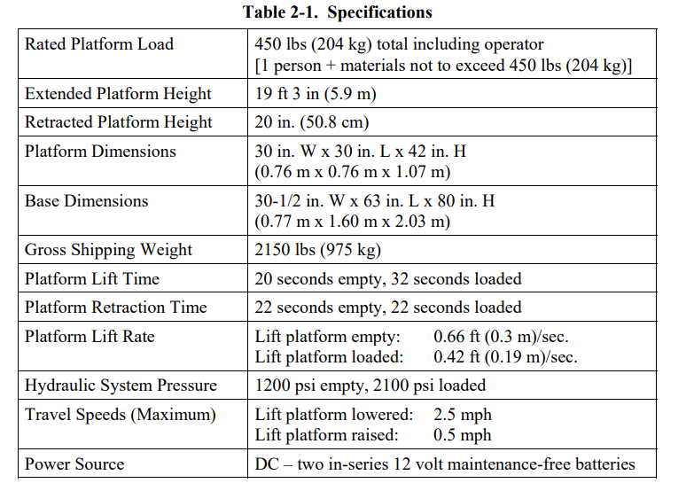
WARRANTY
Bil-Jax warrants its telescopic lifts for one year from the date of delivery against all defects of material and workmanship, provided the unit is operated and maintained in compliance with Bil-Jax’s operating and maintenance instructions; structural components are warranted for three years. Bil-Jax will, at its option, repair or replace any unit or component part that fails to function properly in normal use.
This warranty does not apply if the lift and/or its component parts have been altered, changed, or repaired without the consent of Bil-Jax or by anyone other than Bil-Jax or its factory trained personnel, nor if the lift and/or its components have been subjected to misuse, negligence, accident or any conditions deemed other than those considered as occurring during normal use.
Components not manufactured by Bil-Jax are covered by their respective manufacturers’ warranties. A list of those components and their warranties is available upon written request to Bil-Jax. Bil-Jax shall not, in any event, be liable for the cost of any special, indirect, or consequential damages to anyone, product, or thing.
This warranty is in lieu of all other warranties expressed or implied. We neither assume nor authorize any representative, or other person, to assume for us any other liability in connection with the sale, rental, or use of this product.
Operation
OPERATOR CONTROLS
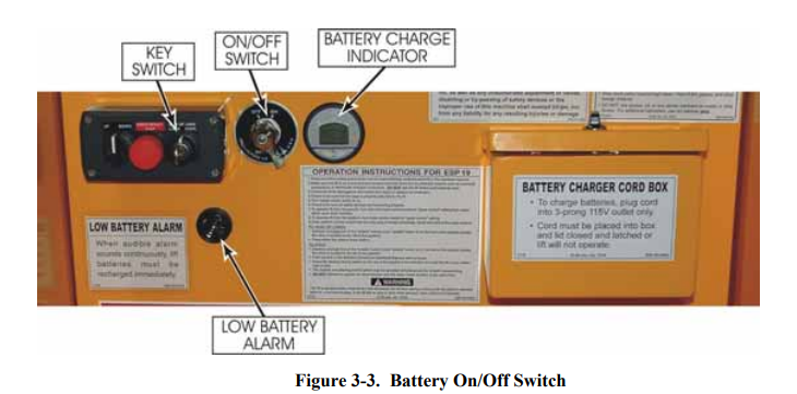
Most of the operator controls for the ESP 19 are located on the upper and lower control boxes. Other operator controls include the BATTERY ON/OFF switch and the emergency lowering valve. The BATTERY ON/OFF switch, located on the left side of the lift base, is the main power disconnect switch for the lift vehicle. The location and operation of the emergency lowering valve are described in paragraph 3-3.
Lower Control Box
The lower control box, Figure 3-1, is located on the lift base and contains three controls: UP/DOWN, EMERGENCY STOP, and UPPER CONTROL/OFF/LOWER CONTROL. The lower control box enables lift operations from floor level. The UPPER CONTROL/OFF/LOWER CONTROL key switch selects the active (upper or lower) control location. To enable an UP or DOWN lift motion from the floor, turn and hold the key switch in the LOWER CONTROL position.
To enable lift vehicle travel or platform elevation from the upper control box, turn the key switch to the UPPER CONTROL position. To disable lift vehicle operations, turn the key switch to the OFF position and remove the key. Turn the UP/DOWN selector switch to the UP position to raise the lift platform or to the DOWN position to lower the platform. (The key switch must be held in the LOWER CONTROL position to enable the UP/DOWN selector switch.)
Press the EMERGENCY STOP button to stop all equipment motion. If the lift vehicle is moving forward or back, pressing the EMERGENCY STOP button engages the travel brake, causing travel to stop quickly. To resume lift vehicle operation, turn the EMERGENCY STOP button clockwise.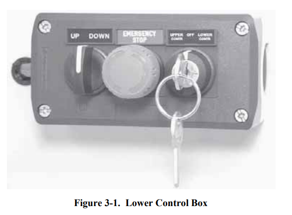
Upper Control Box
The upper control box, Figure 3-2, is in the lift cage. The upper control box enables lift and travel operations whenever the BATTERY ON/OFF switch is in the ON position and the lower control box key switch is in the UPPER CONTROL position. Upper control box controls include four pushbuttons and a forward/reverse floor-travel joystick with thumb-switch steering.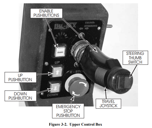
Press and hold either one of the ENABLE pushbuttons to enable a control function. An ENABLE pushbutton must be pressed to enable the lift, steering, and travel functions. The ENABLE pushbutton must be held down to continue the equipment function. With one of the ENABLE pushbuttons depressed, press the UP [↑] pushbutton to raise the platform or press the DOWN [↓] pushbutton to lower the platform. With one of the ENABLE pushbuttons depressed, move the travel joystick forward or back to move the lift vehicle in the forward or reverse direction.
For slow speeds, move the joystick forward or back just a little. For faster speeds, move the joystick more. With one of the ENABLE pushbuttons depressed, press the left or right side of the thumb switch to steer the rear wheels to the left or right. The steering can be adjusted before or during floor travel. Press the EMERGENCY STOP button to stop all equipment motion. If the lift vehicle is moving forward or back, a travel brake is applied, causing travel to stop. To resume lift vehicle operations, turn the EMERGENCY STOP button clockwise.
NORMAL OPERATING PROCEDURE
Perform the following procedures to operate the ESP 19 platform lift vehicle.
- Read and follow all safety precautions contained in Section 1 and all responsibilities outlined in the ANSI A92.3 reprint in Section 7 of this manual.
- Check the lift vehicle for damage or worn parts. If damage or part wear is found, do not operate the vehicle until the problem is corrected.
- Make sure the battery charger cord is disconnected from the wall outlet. Place the cord back into its box and close and latch the lid. LIFT WILL NOT OPERATE IF THE LID IS NOT CLOSED SECURELY.
- Turn the BATTERY ON/OFF switch, Figure 3-3, to the ON position.
- Observe the battery charge level indicator. Verify that the battery charge level is 3/4 or more.

- Turn the UPPER CONTROL/OFF/LOWER CONTROL key switch, Figures 3-1 & 3-3, to the UPPER CONTROL position.
- Enter the platform cage and close the entry gate. LIFT WILL NOT OPERATE IF THE GATE IS NOT CLOSED COMPLETELY.
- Use the upper control box controls to operate the lift vehicle.
- Position the lift vehicle at the work area. Make sure the vehicle is on a firm and level surface and that there are no potential hazards such as speed bumps, open floor drains, potholes, overhead obstructions, or electrically charged conductors. Do not operate the lift vehicle if such hazards exist in the immediate area. NOTE: The lift vehicle is equipped with a level sensor. When the vehicle is on a slope greater than 1 degree, the level sensor disables all functions other than platform lowering and sounds an alarm beeper. Once the platform is lowered, floor travel is again enabled to allow travel to a level area.
- During floor travel and lift operations, the alarm beeper should sound. If the alarm beeper does not work properly, do not operate the lift vehicle.
- During lift platform descent, the amber caution light should blink on and off. If the caution light does not blink on and off, do not use the lift vehicle.
- If any equipment motion continues after the pushbutton, joystick, or selector switch is released, press the EMERGENCY STOP pushbutton, Figure 3-2. All equipment motion should stop immediately.
- At the end of each workday and whenever a low battery alarm sounds, transport the lift vehicle to the recharge site and plug in the charge cord. Verify that the ON-CHARGING indicator lights up on the battery charger. NOTE: For more information on battery charging operations, refer to the battery charging procedure in paragraph 4-4.
- To shut down the equipment, turn the UPPER CONTROL/OFF/LOWER CONTROL key switch and the BATTERY ON/OFF switch to OFF. Remove the key to prevent unauthorized equipment operation
EMERGENCY LOWERING PROCEDURES
In an emergency, a person at floor level can lower the platform by holding the UPPER CONTROL/OFF/LOWER CONTROL key switch in the LOWER CONTROL position and turning the UP/DOWN selector switch to the DOWN position. (If the upper control box emergency stop pushbutton is depressed, the platform will not lower.) An emergency lowering valve is shown in Figure 3-4. In case of a total loss of battery power, a person at floor level can safely lower the platform by opening the emergency lowering valve.
WARNING: Do not climb out of the lift cage while the lift platform is elevated. The lift mast cannot be climbed safely. An elevated lift platform has a high center of gravity and can be tipped easily. Standing on or leaning out from the outside of a cage rail may cause the lift vehicle to tip over. Tipping the lift vehicle over can cause severe injury or death and equipment damage.
If you lose power while elevated in the cage, instruct someone on ground level to open the emergency lowering valve. Do not leave the cage to climb down the lift mast or storage shelves. To lower the platform, pull and hold the red valve knob until the platform starts to descend. When the platform is fully lowered, release the knob to close the valve.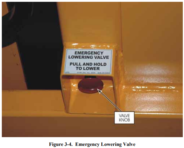
LIFT VEHICLE TRANSPORT
The platform vehicle is equipped with lifting and towing features, Figure 3-5. Read the following instructions before using these features to lift or tow the vehicle.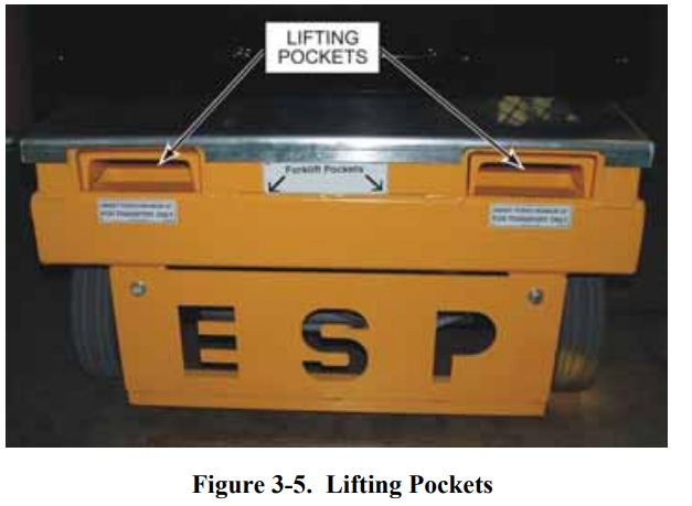
CAUTION: Do not attempt to push the lift vehicle or use the lift vehicle to pull another vehicle or object. Pushing the lift vehicle or using the vehicle for towing may cause serious equipment damage. The forks of a lift truck (2-ton minimum capacity) can be used to raise the ESP 19 for loading onto a trailer or for blocking up the lift vehicle for maintenance.
Forks must be inserted a minimum of 32 inches before raising the ESP 19. Before towing the ESP 19 lift vehicle, you must manually disengage the travel brake and disconnect the steering cylinder from the steering linkage. Refer to the illustrations in Figure 3-6.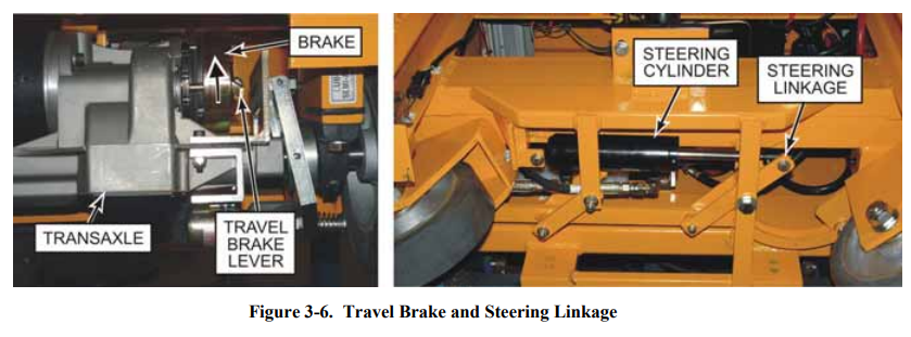
Maintenance
SCHEDULED SERVICE CHECKS
Daily/Weekly Service Checks
Perform the daily and weekly service checks listed in Table 4-1.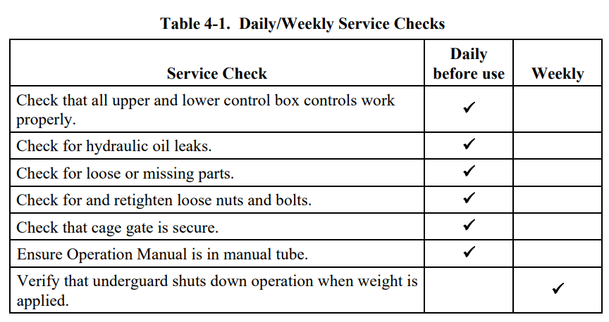
6 Month/Yearly Service Checks
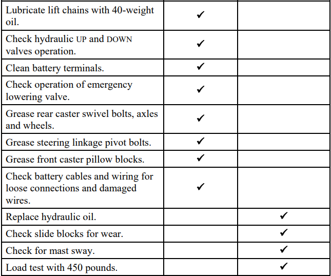
Perform the service checks in Table 4-2 every 6 months or every 12 months, as indicated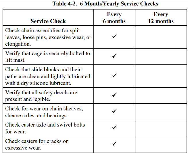
UNDERGUARD SERVICE CHECK
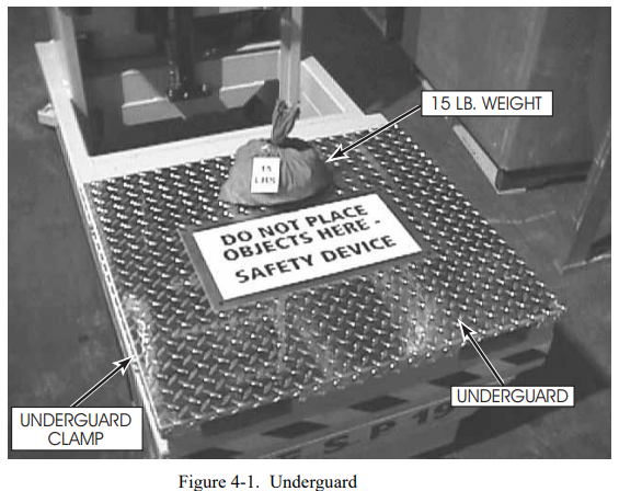
The under guard is a safety device located under the cage/platform that shuts down the operation of the lift when weight is applied. Perform the following procedure weekly to verify that the under guard is working properly.
- Turn the power to lift ON and raise the cage/platform using the lower control box a minimum of 3 feet above the underguard.
- Place a weight of at least 15 lbs. on the under guard. Refer to Figure 4-1.

- BEFORE ATTEMPTING TO LOWER THE LIFT, MAKE SURE THE AREA UNDERNEATH AND AROUND THE CAGE/PLATFORM IS CLEAR OF PERSONNEL OR OTHER OBJECTS. Using the lower control box with power ON, attempt to lower the lift. A warning beeper should sound, and the lift should not lower. The lift should still be able to raise. With someone in the cage, switch to upper controls and attempt to drive. A warning beeper should sound, and the lift should not drive.
- If the lift lowers or drives, the switches below the under guard may need to be adjusted or replaced. To adjust or replace underguard switches, shut the power OFF to lift, then remove two of the under guard clamps from one side of the lift. The switches below the underguard can be adjusted by loosening the screws or removed for replacement.
- Retest whenever under guard is removed and switches are adjusted or replaced.
LUBRICATION
Lubrication makes the operation of the ESP 19 more efficient and extends the life of the lift vehicle. Perform the following lubrication procedures.
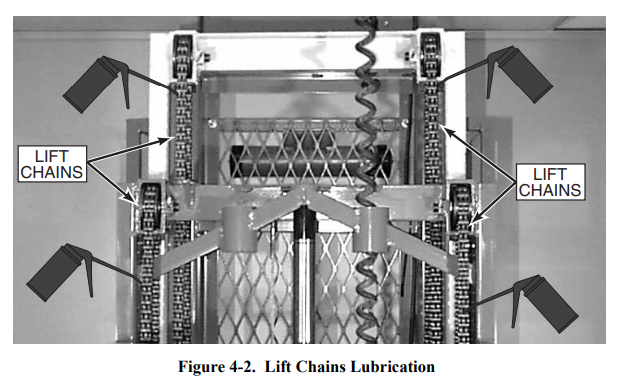
- Lubricate lift chains with clean 40-weight oil. Refer to Figure 4-2.

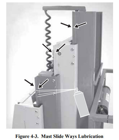
- Clean the mast slide ways, Figure 4-3, and lightly spray the slide ways with a dry silicone lubricant. NOTE: The slide blocks have a high level of lubricity and need only be kept clean. To reduce wear and extend service life, the slide ways should be cleaned and lightly lubricated with a dry-type silicon lubricant.

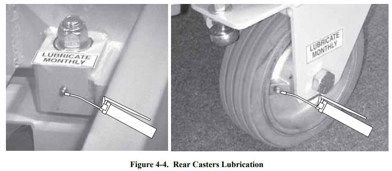
- See Figure 4-4. Grease rear caster axles and swivel bolts at the grease fittings provided. Add about 1/2 ounce of clean #2 NGLI grease to each fitting.

- Remove, clean, and lubricate the steering linkage with wheel bearing grease.
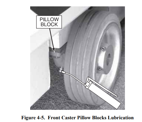
- Apply about 1/2 ounce of clean #2 NGLI grease to the fitting on each front wheel pillow block, Figure 4-5. Do not over-grease the pillow block bearings.

HYDRAULIC SYSTEM
Hydraulic system maintenance varies by the amount of use and the environment in which the lift vehicle is used. Keeping the hydraulic oil clean and the reservoir properly filled will help prevent possible damage to the system.
Hydraulic System Inspection
Check all hydraulic hoses and fittings for leaks and damage daily. Tighten or replace as necessary to prevent hydraulic oil loss.
Fluid Check and Replacement.
With the platform in its lowest position, the hydraulic oil level should be at the MAXIMUM level mark (1-1/2 in. from the top of the reservoir). The reservoir is initially filled with Energol HLP-HD46 (BP Oil), a high-grade, nonfoaming hydraulic oil. This oil is recommended for use in climatic temperatures as low as -20°F/-29°C. Dextron Automatic Transmission Fluid Type A is recommended for use in temperatures as low as -40°F/-40°C.
If either of these oils is not available, a good grade SAE 10W hydraulic oil may be used where the minimum climatic temperature is above 32°F/0°C. An SAE 5W hydraulic oil may be used where temperatures are as low as 0°F/-18°C. Do not mix different hydraulic oils. Clean the reservoir and sump strainer and replace the hydraulic oil at least once a year. Clean the reservoir and sump strainer and replace the oil whenever contamination is suspected.
Hydraulic System Air Bleeding Procedure:
Delayed response or uneven movement of the hydraulic cylinder may indicate trapped air in the hydraulic oil. NOTE: Whenever the upper control box emergency stop pushbutton is engaged, lift operation remains enabled at the lower control box. However, the UP or DOWN lift motion will be intermittent. Intermittent lift motion should not be mistaken for trapped air in the hydraulic system. Perform the following procedure to bleed trapped air from the hydraulic system.
- Fill the reservoir to the MAXIMUM level with the proper hydraulic fluid.
- Fully raise the lift platform.
- Lower the lift platform to allow oil with entrapped air to return to the reservoir. Be careful not to overflow the hydraulic reservoir.
- Leave the lift platform down and the lift vehicle at rest for 10 to 15 minutes while air escapes the hydraulic oil.
- Repeat steps 2 through 4 as needed. Each time the platform is lowered, refill the reservoir to prevent pumping more air into the hydraulic cylinder.
Pressure Relief Valve Adjustment
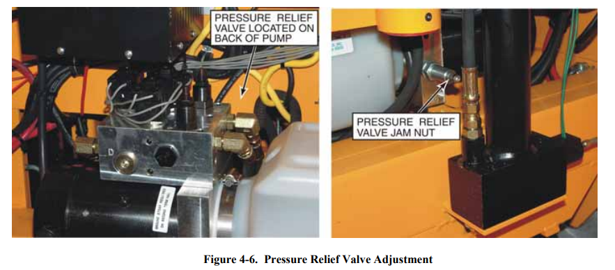
Perform the following procedure to adjust the pressure relief valve. Refer to Figure 4-6.
- Move the ESP 19 lift platform to the fully DOWN position.
- Center 450 pounds of weight on the lift platform.
- Loosen the jam nut. The pressure relief valve is on the back side of the pump.
- Turn the pressure relief valve adjust screw 1/8th turn counterclockwise. This will adjust the relief valve bypass pressure setting for less than 450 pounds of lift.
- Place the key switch in the LOWER CONTROL position and press the UP pushbutton. The pump should run, bypassing oil to the hydraulic reservoir. CAUTION: Do not adjust the pressure relief valve for a bypass pressure higher than needed to raise the 450-pound load. Hydraulic system overload may occur at a higher bypass pressure, causing hydraulic failures or damage to the equipment.
- With the platform lift function enabled (pump running), turn the pressure relief valve adjust screw clockwise just enough to smoothly raise the platform without bypassing oil to the hydraulic reservoir.
- Retighten the jam nut.

For More Manuals By Bil-Jax, Visit ManualsLibraryy.
Bil-Jax ESP-19 Electric Man-Lift Aerial-FAQs
What is the maximum platform height of the Bil-Jax ESP-19?
The ESP-19 provides a platform height of 19 feet, giving safe elevated access for work at height.
How is the lift powered?
It operates electrically, using rechargeable batteries that must be charged with the supplied charger before use.
What is the maximum platform capacity?
The lift supports a safe working load of up to 350 lbs (159 kg), including operator and tools.
Can the ESP-19 be moved while elevated?
No, the lift must be lowered completely before moving to a new location to ensure safety.
How do I control the lift?
It features ground and platform-mounted controls, allowing operation from either position.
What surface is required for safe use?
Always position the lift on a firm, level surface. Do not operate on uneven or sloped ground.
What safety features are included?
The lift includes emergency stop buttons, limit switches, and safety interlocks to prevent unsafe operation.
How often should the lift be inspected?
Perform a pre-use inspection daily and schedule regular maintenance checks as recommended in the manual.

