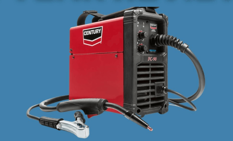
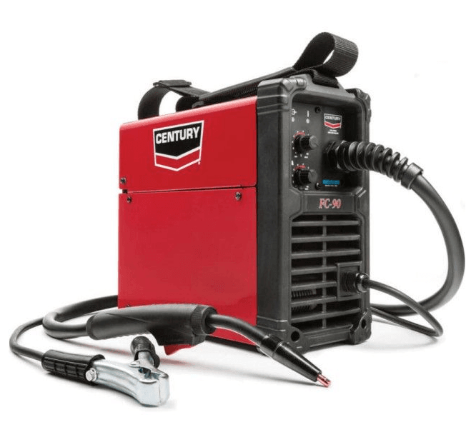
Century FC 90 Flux Cored Wire Feed Welder
SECTION A: WARNINGS
FOR ENGINE POWERED EQUIPMENT.
- Turn the engine off before troubleshooting and maintenance work unless the maintenance work requires it to be running.
- Operate engines in open, well-ventilated areas or vent the engine exhaust fumes outdoors.
- Do not add the fuel near an open flame welding arc or when the engine is running. Stop the engine and allow it to cool before refueling to prevent spilled fuel from vaporizing on contact with hot engine parts and igniting. Do not spill fuel when filling the tank. If fuel is spilled, wipe it up and do not start the engine until fumes have been eliminated.
- Keep all equipment safety guards, covers, and devices in position and in good repair. Keep hands, hair, clothing, and tools away from V-belts, gears, fans, and all other moving parts when starting, operating or repairing equipment.
- In some cases, it may be necessary to remove safety guards to perform required maintenance. Remove guards only when necessary and replace them when the maintenance requiring their removal is complete. Always use the greatest care when working near moving parts.
- Do not put your hands near the engine fan. Do not attempt to override the governor or idler by pushing on the throttle control rods while the engine is running.
- To prevent accidentally starting gasoline engines while turningthe engine or welding generator during maintenance work,disconnect the spark plug wires, distributor cap or magneto wireas appropriate.
- To avoid scalding, do not remove the radiator pressure cap when the engine is hot.
ELECTRIC AND MAGNETIC FIELDS MAY BE DANGEROUS
- Electric current flowing through any conductor causes localized Electric and Magnetic Fields (EMF). Welding current creates EMF fields around welding cables and welding machines
- EMF fields may interfere with some pacemakers, and welders having a pacemaker should consult their physician
before welding. - Exposure to EMF fields in welding may have other health effects that are now unknown.
- All welders should use the following procedures in order to minimize exposure to EMF fields from the welding circuit:
- Route the electrode and work cables together – Secure them with tape when possible.
- Never coil the electrode lead around your body.
- Do not place your body between the electrode and work cables. If the electrode cable is on your right side, the
work cable should also be on your right side. - Connect the work cable to the workpiece as close as possible to the area being welded.
- Do not work next to a welding power source.
ARC RAYS CAN BURN.
- Use a shield with the proper filter and cover plates to protect your eyes from sparks and the rays of the arc when welding or observing open arc welding. Headshield and filter lens should conform to ANSI Z87. I standards.
- Use suitable clothing made from durable flame-resistant material to protect your skin and that of your helpers from the arc rays.
- Protect other nearby personnel with suitable, non-flammable screening and/or warn them not to watch the arc nor expose themselves to the arc rays or to hot spatter or metal.
INSTALLATION
TECHNICAL SPECIFICATIONS -K3493-1 – FC-90
- OUTPUT CURRENT RANGE: 30-90 A
- OPEN CIRCUIT VOLTAGE: 19V (RMS)
- OUTPUT AMPS: 80A
- INPUT CIRCUIT: 120VAC
- DUTY CYCLE: 30%@80A
- WIREFEED SPEED: 0 – 120 IPM
- SUITABLE WIRE DIAMETER: 0.030”, 0.035”
- GROSS WEIGHT: 15 LBS (7KGS)
- IPS RATING: IP21S
Premium features include:
- Inverter power source – more efficient to operate, provides smoother weld characteristics than traditional welders
- Infinite welding voltage to allow fine-tuning of weld characteristics
- 30% Duty cycle at 80 Amps
- Lightweight and portable – Ideal for maintenance and mobile welders
Thermal Protection
The machine has a maximum output duty cycle of 30%. If the duty cycle is exceeded, a thermal protector will shut off the output until the machine cools to a normal operating temperature. This is an automatic function of the machine and does not require user intervention.
Required accessories
- Helmet
- Jacket
- Gloves
CAUTION
The high frequency generator being similar to a radio transmitter may cause interference to radio, TV and other electronic equipment.
- These problems may be the result of radiation interference. Proper grounding methods can reduce or eliminate this. Radiated interference can develop in the following ways
- Direct interference from the welder’s power source
- Direct interference from the welding leads
- Direct interference radiated from feedback into power lines
- Interference from re-radiation by unground metallic objects
Keeping these contributing factors in mind, installing equipment as per the following instructions should minimize problems
- Keep the welder’s input power lines as short as possible and enclose as much of them as possible in metal conduit or equivalent shielding. There should be a good electrical contact between this conduit and the ground (Earth)
- Keep the work and electrode leads as short as possible. Tape the leads together where practical
- Be sure the torch and earth leads rubber coverings are free from cuts and cracks that allow welding power leakage
- Keep the earth lead connection to work in good condition – Clean the area on the workbench where the earth clamp is situated on a regular basis.
Input Power Connection
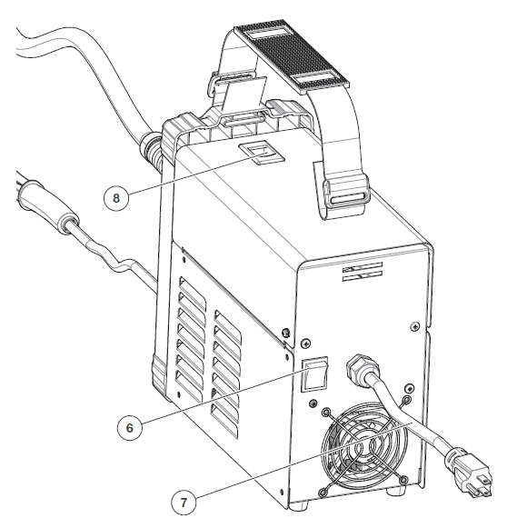
The machine has one input connection, the power input cable. The power input cable is located on the rear. The FC-90 is provided with a 120V cable, 6.0ft.(1.8m) in length, with a 15Amp 5-15P plug molded onto the cord. The rated output of the FC-90 is available when connected to a 20A branch circuit. When connected to a branch circuit with lower capacity, lower welding current and duty cycle must be used.
CODE REQUIREMENTS FOR ELECTRICAL INPUT CONNECTIONS
The National Electrical Code provides standards for amperage handling capability of supply conductors based on duty cycle of the welding source. If there is any question about the installation meeting applicable electrical code requirements, consult a qualified electrician.
EXTENSION CORD USAGE
If an extension cord is required, use one that is rated for the application and is 3-conductor #14 AWG (2.1 mm2) or larger. The recommended maximum lengths are 25 ft (7.5 m) if #14 AWG (2.1 mm2) is used and 50 ft (15 m) if #12 AWG (3.3 mm2) is used.
FLUX-CORED (INNERSHIELD) WELDING
The recommended electrode for the flux-cored, self-shielded process is 0.035” (0.9 mm) diameter Lincoln Innershiel NR-211-MP on 1 lbs. (.5 kg) spools.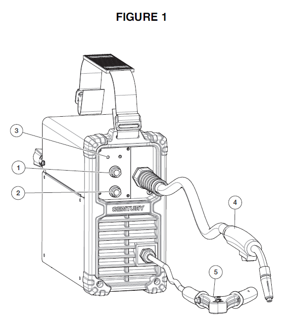
- Adjustment for Voltage
- Adjustment for Wire feed speed
- Power and protection LEDs
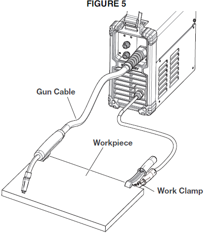
- Gasless Flux-Cored torch
- Work Clamp

- Power Switch
- Power Input Cable
- Spool cover latch
Wire loading and threading
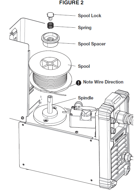
Refer to Figure 2. Turn the machine power switch to the OFF (“0”) position before working inside the wire feed enclosure. Make sure that the wire feed drive roll and the contact tip of the gun match the diameter and type of wire used.
- Push the spool onto the spindle so that the wire feeds off the bottom of the spool, toward the drive roll.
- Push the spool spacer onto the spindle, against the spool.
- Slide the spring onto the spool, then press on the spool lock, turning it clockwise to lock the spool assembly onto the spindle.
WIRE THREADING DETAILS
Refer to Figure 3.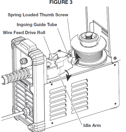
- Release the spring loaded thumb screw and rotate the idle roll arm away from the wire feed drive roll. Ensure that the visible, stenciled size on the drive roll side facing you matches the wire size being used.
- Carefully detach the end of the wire from the spool. Maintain tension on the wire to prevent the spool from unwinding, and do not release the wire until after step 5.
- Cut the bent portion of the wire off and straighten the first 4” (100 mm).
- Thread the wire through the incoming guide tube, over the drive roll, and into the gun liner.
- Close the idle roll arm and turn down the thumbscrew until the idle roller presses down firmly on the wire. (Now you may release the welding wire). Make sure the wire is positioned in the groove of the lower drive roll.
- The spring-loaded thumbscrew on the idle roll arm adjusts the pressure on the wire. Adjust pressure by turning the thumbscrew to prevent spool overrun, but still allow smooth and easy wire feeding. Start with the pressure set to an intermediate value. Readjust, if necessary. If the drive roll slips while feeding wire, the pressure should be increased until the wire feeds properly.
WIRE STICKOUT
- Remove the contact tip and nozzle from the gun.
- Turn the machine ON (“I”).
- Straighten the gun cable assembly.
- Depress the gun trigger switch and feed welding wire through he gun and cable. (Point the gun away from yourself and others while feeding wire). Release the gun trigger after wire appears at the end of the gun.
- Turn off the machine.
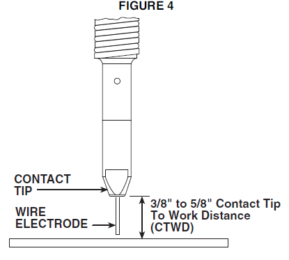
- Replace the nozzle and contact tip. Refer to Figure B-4. Cut the wire off so that 3/8” to 5/8” (10 – 15 mm) protrudes from the end of the tip.
- Turn on the machine. The machine is now ready to weld.

OPERATION
Read and understand this entire section before operating your CrossLinc Remote.
Safety Precautions
Do not attempt to use this equipment until you have thoroughly read all operating and maintenance manuals supplied with your equipment and any related welding machine it will be used with. They include important safety precautions, operating and maintenance instructions and parts lists.
WARNING
ELECTRIC SHOCK can kill.
- Do not touch electrically live parts such as output terminals or internal wiring.
- Insulate yourself from the work and ground.
- Always wear dry insulating gloves.
WELDING SPARKS can cause fire or explosion.
- Keep flammable material away.
- Do not weld upon containers that have held combustibles.
ARC RAYS can burn.
- Wear eye, ear and body protection.
FUMES AND GASES can be dangerous.
Although the removal of the particulate matter from welding smoke may reduce the ventilation requirement, concentrations
of the clear exhausted fumes and gases may still be hazardous to health. Avoid breathing concentrations of these fumes and gases. Use adequate ventilation when welding. See ANSI Z49.1, “Safety in Welding and Cutting”, published by the American Welding Society.
Operating machine
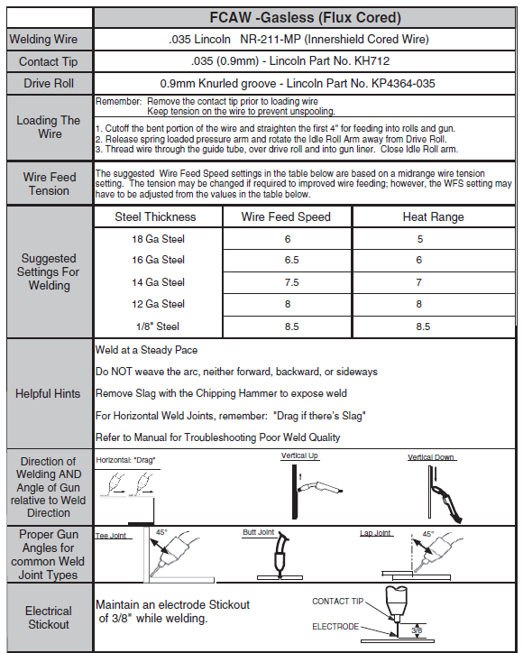
Once you have set the machine up as per the instructions, refer to Table B.1 and the Procedure Decal located on the inside of the wire drive compartment door of your machine for setup information, consumables, and quick tips for welding.
- Select welding voltage (power), based on the material thickness of the workpiece, required on the front panel
- Select wire feed speed required on ‘wire speed’ knob
- Ensure you are wearing the correct safety clothes & equipment for welding (I.E, Welding mask, gloves, apron, etc)

- Connect the work clamp to the metal to be welded. The work clamp must make good electrical contact to the work piece. The work piece must also be grounded as stated in Arc Welding Safety Precautions in the beginning of this manual.
- Based on the weld joint type and orientation of the weld joint, position the gun into the joint at the correct angle.
- To begin welding, raise your hand shield or lower your helmet to protect your eyes and pull the trigger.
- While welding, travel at a constant speed and maintain an electrode stickout of 3/8″.
- To stop welding, release the gun trigger.
- When no more welding is to be done, turn off the machine.
TABLE B.1
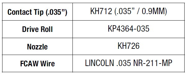
Replace Parts list
WARNING: Use of this unit on thicker materials than recommended may result in welds of poor quality. The welds may appear to be fine, but may lack the fusion or bonding necessary to give a strong weld. This is called “Cold Casting” or “cold lapping” and is somewhat similar to a cold solder joint. Weld failure may result.
MAINTENANCE
WARNING
ELECTRIC SHOCK can kill.
- Turn the input power OFF at the welding power source before installation or changing drive rolls and/or guides.
- Do not touch electrically live parts.
- When inching with the gun trigger, the electrode and drive mechanism are “hot” to work and ground and could remain energized several seconds after the gun trigger is released.
- Do not operate with covers, panels or guards removed or open.
- Only qualified personnel should perform maintenance work.
Items requiring no maintenance
- Drive Motor and Gearbox – Lifetime lubrication
- Wire Reel Spindle – Do NOT lubricate the shaft
Routine and Periodic maintenance
- BEFORE EACH USE – Check over the machine and accessories for any obvious condition that may prevent safe performance or operation. Repair or replace items as necessary to correct any abnormal condition.
After 5 minutes of welding or when spatter accumulates on the contact tip:
- CLEANING TIP AND NOZZLE – With the power switch in the off position, keep the contact tip and nozzle clean to avoid arc bridging between them. Bridging can result in a shorted nozzle, poor welds and an overheated gun.
Hint: Anti-stick spray or gel, available from a welding supplier, may reduce buildup and aid in spatter removal.
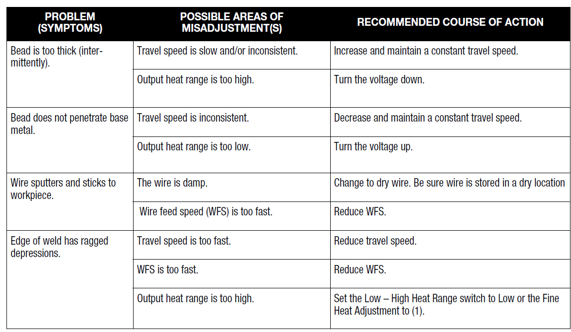
TROUBLESHOOTING
HOW to use the Troubleshooting Guide
This Troubleshooting Guide is provided to help you locate and repair possible machine malfunctions. Simply follow the three-step procedure listed below.
- Step 1. LOCATE PROBLEM (SYMPTOM).
Look under the column labeled “PROBLEM (SYMPTOMS).” This column describes possible symptoms that the machine may exhibit. Find the listing that best describes the symptom that the machine is exhibiting. - Step 2. POSSIBLE CAUSE.
The second column labeled “POSSIBLE CAUSE” lists the obvious external possibilities that may contribute to the machine’s symptoms. - Step 3. RECOMMENDED COURSE OF ACTION
This column provides a course of action for the Possible Cause, generally it states to contact you local Lincoln Authorized Field Service Facility.
If you do not understand or are unable to perform the Recommended Course of Action safely, contact your local Lincoln Authorized Field Service Facility.
CUSTOMER ASSISTANCE POLICY
The business of The Lincoln Electric Company is manufacturing and selling high quality welding equipment, consumables, and cutting equipment. Our challenge is to meet the needs of our customers and to exceed their expectations. On occasion, purchasers may ask Lincoln Electric for advice or information about their use of our products. We respond to our customers based on the best information in our possession at that time. Lincoln Electric is not in a position to warrant or guarantee such advice, and assumes no liability, with respect to such information or advice. We expressly disclaim any warranty of any kind, including any warranty of fitness for any customer’s particular purpose, with respect to such information or advice. As a matter of practical consideration, we also cannot assume any responsibility for updating or correcting any such information or advice once it has been given, nor does the provision of information or advice create, expand or alter any warranty with respect to the sale of our products. Lincoln Electric is a responsive manufacturer, but the selection and use of specific products sold by Lincoln Electric is solely within the control of, and remains the sole responsibility of the customer. Many
variables beyond the control of Lincoln Electric affect the results obtained in applying these types of fabrication methods and service requirements. Subject to Change – This information is accurate to the best of our knowledge at the time of printing. Please refer to www.lincolnelectric.com for any updated information.
For more manuals by Blogs, visit ManualsLibraryy
Century FC 90 Flux Cored Wire Feed Welder-FAQs
What can I use a flux core welder for?
Flux core welders are ideal for outdoor projects and construction work due to their portability and fast welding speed. They’re commonly used in shipbuilding, structural welding, and general metal fabrication.
How does a wire feed welder work?
Wire feed welders use a continuous wire electrode and constant voltage to create an arc that melts the wire and joins it with the base metal. Shielding gas (or internal flux) protects the weld from air contamination.
Does flux core welding require gas?
No external gas is needed when using self-shielded flux-cored wire, as the flux inside the wire produces a gas shield during welding. This makes it great for outdoor or windy conditions.
What welding angle should I use with flux core wire?
In flat positions, keep a work angle of 90°, and use a drag angle between 2° and 15° for best results.
Is flux core welding done with AC or DC?
Flux core welding is typically performed with DC output using negative polarity (DCEN) to reduce contamination and ensure stable arc performance.
What is the best wire feed speed for this welder?
Recommended wire feed speed is usually between 240–290 inches per minute (ipm) with a travel speed of 14–19 ipm. Keep the wire stickout at 5/8 inch or less for better control.
What gas should I use with flux-cored wire?
Gas-shielded flux core wires work best with 100% CO₂ or a 75% argon / 25% CO₂ mix. For windy or outdoor conditions, self-shielded flux core wire is preferred since it doesn’t require external gas.
Can I weld with flux core wire without gas?
Yes, you can weld without gas using self-shielded flux core wire. It’s especially useful in environments where shielding gas would be blown away, like outdoors.
What voltage is needed for flux core welding?
Typical voltage settings for flux core welding range between 17 to 22 volts and 50 to 275 amps, depending on the wire diameter and application.

