
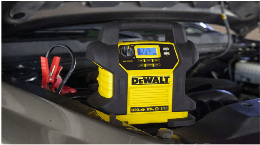
DeWALT DXAEJ14 Jump Starter with Digital Compressor
Specific Safety Instructions for Jump Starters
- WARNING – Burst hazard: Do not use the unit for charging dry-cell batteries that are commonly used with home appliances. These batteries may burst and cause injury to persons and damage property. Use the unit for charging/boosting a lead-acid battery only. It is not intended to supply power to a low-voltage electrical system other than in a starter-motor application.
- WARNING: To reduce the risk of electric shock, never immerse this unit in water or any other liquid, or use when wet.
- WARNING – Risk of explosive gases:
- Working in the vicinity of a lead-acid battery is dangerous. Batteries generate explosive gases during normal battery operation. For this reason, it is of the utmost importance that each time before using the jump-starter you read this manual and follow instructions exactly.
- To reduce the risk of battery explosion, follow these instructions and those published by the battery manufacturer and manufacturer of any equipment you intend to use in the vicinity of the battery. Review cautionary markings on these products and on the engine.
- WARNING – To reduce the risk of fire:
- Do not operate near flammable materials, dust, fumes or gases.
- Do not expose to extreme heat or flames.
- CAUTION – To reduce the risk of injury or property damage:
- NEVER ATTEMPT TO JUMP-START OR CHARGE A FROZEN BATTERY.
- Vehicles that have on-board computerized systems may be damaged if vehicle battery is jump-started. Before jump-starting, read the vehicle’s owner’s manual to confirm that external-starting assistance is suitable.
- When working with lead acid batteries, always make sure immediate assistance is available in case of accident or emergency
Components (Fig. 1)
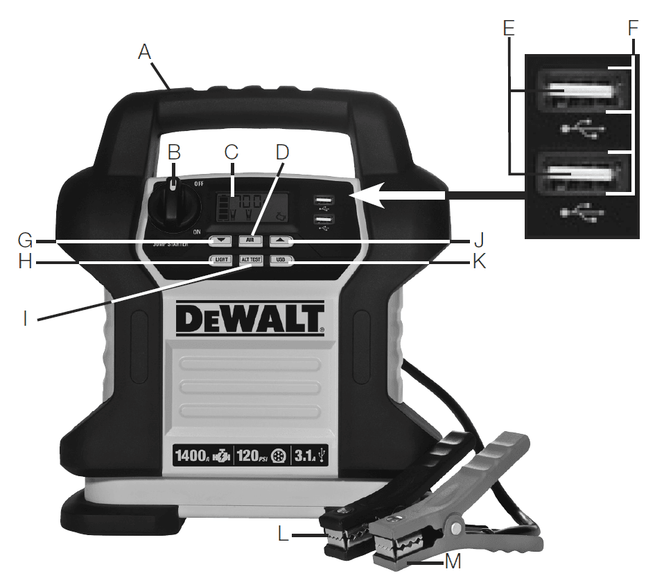
- A. Handle
- B. Jump Starter Power Switch
- C. Backlit LCD Screen
- D. Compressor Power Button
- E. USB Ports
- F. USB Power/Fault Indicators
- G. Decrease Compressor Pressure Control Button (
 )
) - H. Area Light Power Button
- I. Alternator Check Button
- J. Increase Compressor Pressure Control Button (
 )
) - K. USB Power Button
- L. Negative (–) Black Clamp
- M. Positive (+) Red Clamp
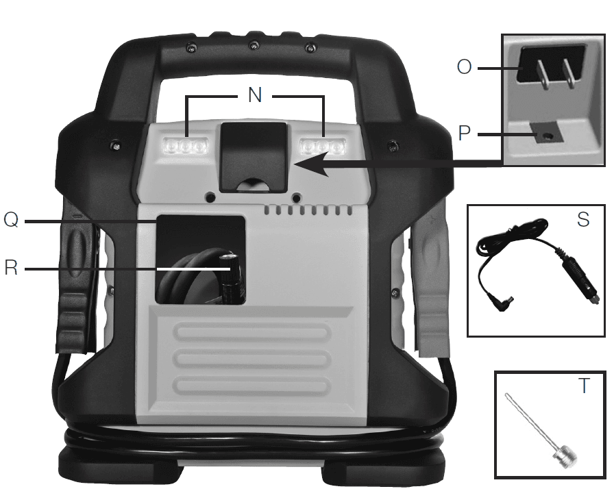
- N. LED Area Light (two banks of three LEDs)
- O. Built-in 120 Volt AC Charger (under protective cover)
- P. 12V DC Charging Port (under protective cover)
- Q. Storage Compartment
- R. Air Hose and SureFit® Nozzle
- S. 12 Volt DC Charging Adapter
- T. Nozzle Adapter

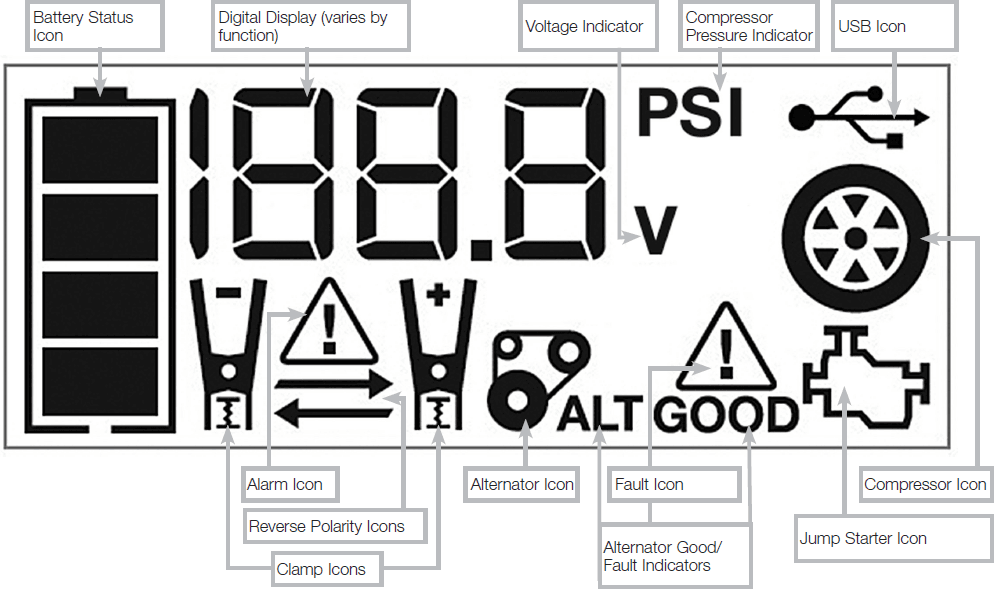
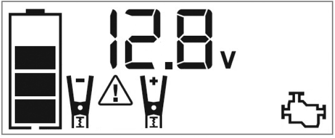
LCD Display Detail (Fig. 2)
Overview
COMMON ACTIONS AND UNIT RESPONSES
The following actions turn the unit on and activate the LCD screen:
| Press the Alternator Check Button. (Refer to the “Alternator Check” section.) | A beep will sound and the backlit LCD screen will display the Battery Status Icon, and the Alternator Icon will flash. The unit remains on until the Alternator Check Button is pressed again to turn it off. |
| Press the LED Area Light Power Button. (Refer to the “LED Area Light” section.) | A beep will sound and the Area Light will turn on. The backlight will turn on for 10 seconds (only). The LCD screen will continue to display the Battery Status Icon and Battery Voltage Indicator. The unit remains on until the LED Area Light Power Button is pressed again to turn it off. |
| Press the USB Power Button. (Refer to the “USB Ports” section.) | A beep will sound and the backlit LCD screen will display the Battery Status Icon, Battery Voltage Indicator, and the USB Icon; and the USB Power/Fault Indicators will light solid blue indicating the two USB Ports are active. The unit remains on until the USB Power Button is pressed again to turn it off. |
| Press the Compressor Power Button. (Refer to the “Portable Compressor” section.) | A beep will sound and the backlit LCD screen will display the Battery Status Icon, “XXX” PSI and the Compressor Icon. If no further actions are taken after 1 minute, the unit will display the Battery Status Icon and Battery Voltage Indicator for 10 seconds before automatically turning off. |
| Whenever the clamps are properly connected to a battery (refer to the “Jump Starter” section) … | … a beep will sound and the backlit LCD screen will display the Battery Status Icon, Battery Voltage Indicator, the Clamp Icons, and the “+” and ”–” signs, as well as the flashing Jump Starter Icon. The unit remains on until the clamps are disconnected from the battery. |
| If the Jump Starter Power Switch is rotated to the on position and the clamps are not connected to a battery (refer to the “Jump Starter” section) … | … a two-second warning will sound every 10 seconds. The backlit LCD screen will display the Battery Status Icon, Battery Voltage Indicator, the Clamp Icons, and the “+” and ”–” signs. The Alarm Icon and the Jump Starter Icon will flash. The unit remains on until the Jump Starter Power Switch is switched off and then displays the Battery Status Icon and the voltage on the digital display for 10 seconds before automatic shut down. |
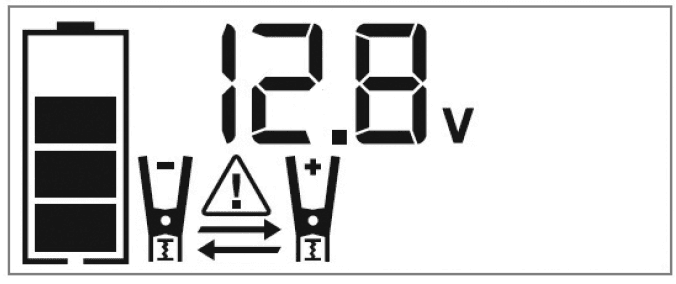
| If the clamp connections to the battery’s positive and negative terminals are reversed (refer to the “Jump Starter” section) … | … the backlit LCD screen will display the Battery Status Icon, Battery Voltage Indicator, and the Clamp Icons. The Alarm Icon, the “+” and ”–” signs and the Reverse Polarity Icons will flash and the unit will sound a warning continuously until the clamps are disconnected from the battery. |
| When the unit is charging or recharging using the built-in 120 Volt AC Charger or the 12 Volt DC Adapter (refer to the “Charging/ Recharging” section) … | … a beep will sound and the backlight will turn on for 10 seconds (only). The LCD screen will continue to display the Battery Status Icon and Battery Voltage Indicator. The bars on the Battery Status Icon will change from empty to solid (bottom to top) repeatedly. |
- NOTE: The unit will automatically power off once ALL the functions and the charging process are turned off.
Viewing Battery Status
The Battery Status Icon and Battery Voltage Indicator indicate the battery charge level as follows: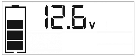
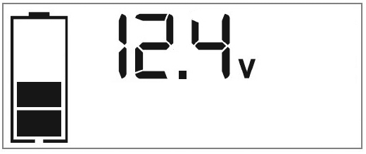
- If the battery charge level is at full capacity, four solid bars will display.
- If the battery is partially charged, two or three solid bars will display.
- If the battery is nearly empty, one solid bar will display. The unit should be charged at this time.
- If the battery is completely empty, four blank bars will display. The unit MUST be charged at this time or the unit’s built-in low voltage protection will activate. The empty Battery Status Icon will flash for a short period of time before automatic shut down. The unit will not operate until the battery is recharged.
Charging/Recharging
- Lead-acid batteries require routine maintenance to ensure a full charge and long battery life. All batteries lose energy from self-discharge over time and more rapidly at higher temperatures. Therefore, batteries need periodic charging to replace energy lost through self-discharge. When the unit is not in frequent use, manufacturer recommends the battery should be recharged at least every 30 days and after each use.
Important Charging Notes
- This unit is delivered in a partially charged state – you must fully charge it before using it for the first time. Initial AC charge should be for 40 hours or until the Battery Status Icon shows 4 solid bars.
- Recharging the battery after each use will prolong battery life; frequent heavy discharges between recharges and/or overcharging will reduce battery life.
- The battery can be recharged using the built-in 120 Volt AC Charger or the 12 Volt DC Adapter.
- Make sure all other unit functions are turned off during recharging, as they can slow the recharging process.
- CAUTION – To reduce the risk of property damage: Failure to keep the battery charged will cause permanent damage and result in poor jump starting performance.
- IMPORTANT: If you know the unit is discharged, but the battery icon displays four solid bars as if the unit is fully charged when connected to a charging power source, this may be due to the internal battery having high impedance. The manufacturer suggests leaving the unit charging for a period of 40 hours using the built-in AC charger before use
Charging/Recharging Using the Built-In 120 Volt AC Charger and AC Extension Cord (not supplied)
- Lift the protective cover of the built-in 120 Volt AC Charger located on the back of the unit (refer to Fig. 1 to locate). Connect an extension cord to the unit. Plug the other end of the cord into a standard 120‑volt AC wall outlet. When the unit is properly connected to an AC power source, the LCD screen will display the following:

- The bars on the Battery Status Icon represent the charge level of the unit’s internal battery. The bars on the Battery Status Icon will change from empty to solid (bottom to top) repeatedly to indicate the unit is charging. The backlight will turn on for 10 seconds (only).
- Charge for approximately 40 hours or until the Battery Status Icon shows 4 solid bars.
- When charging is complete, unplug the AC extension cord from the AC outlet and then disconnect it from the unit
Jump-Starter
- This unit is equipped with a jump starter power switch that allows energy to flow only when proper connections are made to battery and frame.
- A. For negative-grounded systems, connect the positive (red) clamp to the positive ungrounded battery post and the negative (black) clamp to the vehicle chassis or engine block away from the battery. Do not connect the clamp to the carburetor, fuel lines or sheet-metal body parts. Connect to a heavy gage metal part of the frame or engine block.
- B. For positive-grounded systems, connect the negative (black) clamp to the negative ungrounded battery post and the positive (red) clamp to the vehicle chassis or engine block away from the battery. Do not connect the clamp to the carburetor, fuel lines or sheet-metal body parts. Connect to a heavy gage metal part of the frame or engine block.
- IMPORTANT: Make sure the Compressor Power Button has been turned off before attempting to use the unit as a Jump Starter
- If the clamps are connected incorrectly with regard to polarity, the unit will sound a continuous alarm until the clamps are disconnected. The backlit LCD Screen will display the Battery Status Icon, the Battery Voltage Indicator and the Clamp Icons. The “+” and”–” signs above the Clamp Icons, the Reverse Polarity Icons and the Alarm Icon will flash. The backlit LCD screen will display the following

- If the Jump Starter Power Switch is turned on and the unit detects that the clamps are not connected to a battery, a two-second warning will sound every 10 seconds. The LCD screen will display the Battery Status Icon, the Battery Voltage Indicator, and the Clamp Icons with the “+” and”–” signs. The Alarm Icon and the Jump Starter Icon will flash. The backlit LCD screen will display the following:

- Turn off the Jump Starter Power Switch; connect the clamps to the battery, making sure the clamps are connected with correct polarity then turn the Jump Starter Power Switch back on
- Always disconnect the negative (black) jumper cable first, followed by the positive (red) jumper cable, except for positive grounded systems.
PROCEDURE
Take the following steps, observing all cautions and warnings in the “Important Safety Instructions” section at the front of this manual.
- Turn off vehicle ignition and all accessories (radio, A/C, lights, connected cell phone chargers, etc.). Place vehicle in “park” and set the emergency brake.
- Make sure the jump-starter power switch is in the off position.
- Remove jumper clamps from clamp tabs. Connect the red clamp first, then the black clamp.
Alternator Check
Set up the unit and connect to the battery following steps 1 through 5 in the “Jump-Starter” section.
Important Notes About the Alternator Check Function
- The unit may detect that the alternator is out of typical voltage range because someone has added a number of accessory loads on the charging system, thereby increasing current demand from the alternator. MAKE SURE THAT THE ALTERNATOR IS RATED TO SUPPORT THE APPLICATION.
- This check may not be accurate for every make, manufacturer and model of vehicle. Check only 12 volt systems.
PART 1
No Load (turn OFF all vehicle’s accessories): The vehicle battery must be fully charged before testing the alternator. Run the engine long enough to achieve normal idle speed and verify there is a no-load voltage.
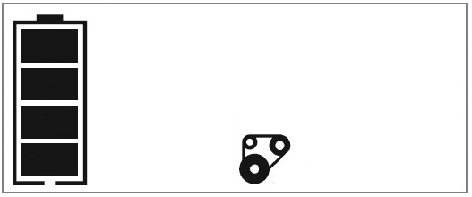
- Press the Alternator Check Button to start the check. The backlit LCD screen will display the following to indicate the unit is analyzing the alternator
 The Battery Status Icon will light solid and the Alternator Icon will flash.
 - If the unit detects that the alternator is good, the backlit LCD screen will display the following
 The Battery Status Icon, Alternator Icon, and “ALT GOOD” will light solid.
 - If the unit detects that the alternator is out of typical voltage range, the backlit LCD screen will display the following
 The Battery Status Icon, Alternator Icon and “ALT” will light solid. The Fault Icon will flash.
 - Press the Alternator Check Button again to stop the test and turn off the unit
PART 2
Under Load (accessories ON): Next, load the alternator by turning on as many accessories as possible (except for A/C and Defrost).
- Press the Alternator Check Button to start the check. The backlit LCD screen will display the following to indicate the unit is analyzing the alternator:
 The Battery Status Icon will light solid and the Alternator Icon will flash.
 - If the unit detects that the alternator is good, the backlit LCD screen will display the following:
 The Battery Status Icon, Alternator Icon, and “ALT GOOD” will light solid
 - If the unit detects that the alternator is out of typical voltage range, the backlit LCD screen will display the following:
 The Battery Status Icon, Alternator Icon and “ALT” will light solid. The Fault Icon will flash.
 - Press the Alternator Check Button again to stop the test and turn off the unit.
- IMPORTANT: Always turn the unit off when not in use. Recharge this unit fully after each use
Portable Compressor
- The built-in 12 volt DC compressor is the ultimate compressor for all vehicle tires, trailer tires and recreational inflatables. A nozzle adaptor is supplied that screws onto the end of the SureFit® nozzle at the freeend of the compressor hose. The compressor hose with tire fitting is stored in the compressor hose storage compartment. Refer to Fig. 1 to locate the compressor hose. The Compressor Power Button and Increase (
 ) and Decrease (
 ) Compressor
 - Pressure Control Buttons are located on the control panel on the front of the unit. Before proceeding, check the unit’s battery status on the LCD screen.
Four solid bars in the battery icon indicates a full battery. When the battery level is nearly empty with only one solid bar, the unit MUST be recharged before use or the unit’s built-in low voltage protection will activate. The empty Battery Status Icon will flash for a short period of time before automatic shut down.
INFLATING TIRES OR PRODUCTS WITH VALVE STEMS
- Screw the SureFit® nozzle onto the valve stem. Do not overtighten.
- Press the Compressor Power Button. A beep will sound and the backlit LCD screen will display the following:
 The Compressor Icon will light and the Digital Display will alternately show the flashing pre-set psi value (that was last set by the compressor pressure control buttons) and the current pressure of the item being inflated (which will light solid).
 - Press the “
 ” and “
  ” Pressure Control Buttons to set the desired pressure from a range pre-set values (between 3 and 120), which will display on the backlit LCD Screen. The unit will sound a beep with each press of the buttons (holding the button speeds up the upward or downward value selection). Once the desired pressure has been entered, release the button and the flashing digital display will show the new selected pressure, as follows:
 The new selected value is now stored in the unit’s memory until it is manually reset.
 - Press the Compressor Power Button once more to begin inflating. The Compressor Icon will flash and the digital display will only show the current pressure value (which will light solid) to indicate the compressor is activated. Monitor the pressure on the LCD Screen.
- IMPORTANT NOTE: To interrupt during inflation, press the Compressor Power Button again.
- When desired pre-set pressure is reached, the compressor will automatically stop.
- Press the Compressor Power Button again to turn off the unit.
- Unscrew and remove the SureFit® nozzle from the valve stem.
- Allow the unit to cool, then recharge before storing away.
- Store the compressor hose and SureFit® nozzle in the storage compartment.
INFLATING OTHER INFLATABLES WITHOUT VALVE STEMS
Inflation of other items requires use of the nozzle adapter.
- Screw the nozzle adapter into the SureFit® nozzle. Do not overtighten.
- Insert the nozzle adapter into item to be inflated.
- Follow steps 2 through 4 of the “Inflating Tires or Products With Valve Stems” section.
- IMPORTANT: Small items such as volleyballs, footballs, etc. inflate very rapidly. Keep this in mind when setting pressure. Take extra care not to over-inflate.
- When the desired pressure is reached, the compressor will automatically stop. Press the Compressor Power Button again to turn off the unit.
- Disconnect the adapter from the inflated item.
- Unscrew and remove the nozzle adapter from the SureFit® nozzle.
- Allow the unit to cool, then recharge before storing away.
- Store the compressor hose, SureFit® nozzle and nozzle adapter in the storage compartment.
USB Ports
The USB Power Button and the two USB Ports are located on the right hand side of unit. The USB Power/Fault Indicator is a translucent ring around each of the USB Ports. Refer to Fig. 1 to locate.
Important Notes Concerning the USB Ports
- The two USB Ports provide a total of 3.1A (5V each).
- When the USB Ports are in use, the unit will monitor for the following USB fault conditions on all the USB Ports: thermal fault, low battery voltage fault, overload and short circuit. If a fault condition exists in either of the USB Ports, the USB Power/Fault Indicators will flash blue. In any of these cases, the backlit LCD screen will continuously display the following:
 The Fault Icon will flash. The USB Ports will automatically shut down. Should this occur:
- a. Disconnect the USB-powered device and press the USB Power Button again to turn off the USB Ports immediately.
- b. Make sure the unit does not need to be recharged.
- c. Allow the unit to cool down for several minutes before attempting to use the USB Ports again.
- d. If a fault occurs again, make sure that the total draw of all USB devices plugged into the USB Ports does not exceed 3.1A.
- e. If an individual USB device is within specifications and the fault occurs, have the USB device checked for malfunction and do not continue to use it with these USB Ports.
- This unit’s USB Ports do not support data communication. They only provide power to external USB-powered devices. The USB Ports provide a total of 3.1A (5V each).
- Some household USB-powered electronics will not operate with this unit.
Care and Maintenance
THE INTERNAL BATTERY
- All batteries lose energy from self-discharge over time and more rapidly at higher temperatures. When the unit is not in use, we recommend that the battery is charged at least every 30 days
BATTERY REPLACEMENT
- The battery should last the service life of the unit. Service life is dependent on a number of factors including but not limited to the number of recharge cycles, and proper care and maintenance of the battery by the end user. Contact manufacturer for any information you may need.
SAFE BATTERY DISPOSAL
- Contains a maintenance-free, sealed, non-spillable, lead acid battery, which must be disposed of properly. Recycling is required. Failure to comply with local, state and federa regulations can result in fines, or imprisonment. Please recycle.
12 VOLT DC ADAPTER PLUG FUSE REPLACEMENT
The fuse in the plug end of the 12 Volt DC Adapter protects the adapter’s charging circuit. If the built-in 120 Volt AC Charger operates, but the DC charging adapter does not, then this fuse may be opened (blown).
To replace the fuse:
- Unscrew the end cap of the DC plug (counterclockwise).
- Remove spring center contact and fuse.
- Check fuse with a continuity checker.
- If blown, locate a replacement 2 amp.
- Replace the fuse, spring, contact and end cap.
- Screw end cap clockwise until it is finger tight – DO NOT OVERTIGHTEN.
- Test for proper operation of the 12 volt DC charging adapter.
For more manuals by DeWALT, visit ManualsLibraryy
DeWALT DXAEJ14 Jump Starter with Digital Compressor-FAQs
How long does a DeWALT jump starter take to charge?
For the initial charge, leave it plugged in for 40 hours to ensure maximum capacity. Future charging times depend on usage.
How does the air compressor work on the jump starter?
The air compressor draws power from the jump starter, similar to how it powers a car battery, and is ready to inflate tires or other items.
How do I know if my DeWALT jump starter is charging?
Check the flash code chart on the front panel. A steady blinking light indicates charging, and a solid red light means fully charged.
How long does a DeWALT battery take to fully charge?
Most DEWALT chargers complete a full charge in about 60 minutes. For maintenance mode charging, leave the battery in the charger overnight.
How does jump-starting work?
A temporary connection is made to an external power source or another vehicle’s battery, providing power to recharge the battery and crank the engine.
How do you safely remove a jump starter?
1. Turn off the engines of both vehicles.
2. Disconnect the black jump lead from the disabled vehicle.
3. Disconnect the black lead from the second vehicle.
4. Finally, disconnect the red jump lead from the second vehicle.
Where is the serial number on a DeWALT jump starter?
The serial number is usually located on the rating label or inside the battery compartment.
How do you turn off a DeWALT air compressor?
Set the Auto/Off switch to the OFF (O) position and unplug the unit. Allow the motor to cool before storing.
Can I leave a DeWALT battery on the charger overnight?
Yes. DEWALT chargers have a maintenance mode to maintain a fully charged battery without damaging it.
How do I know when my jump starter is fully charged?
Indicator lights will show the charging status. A fully charged jump starter typically shows a solid light.

 The Battery Status Icon will light solid and the Alternator Icon will flash.
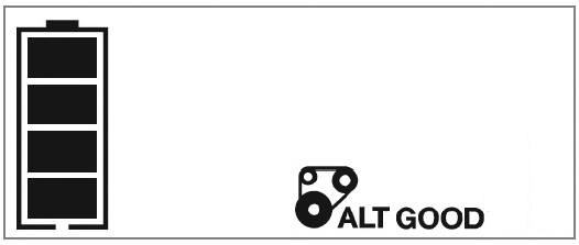 The Battery Status Icon, Alternator Icon, and “ALT GOOD” will light solid.
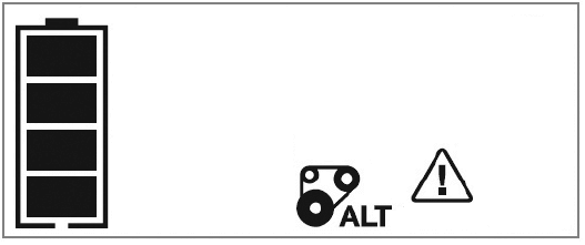 The Battery Status Icon, Alternator Icon and “ALT” will light solid. The Fault Icon will flash.
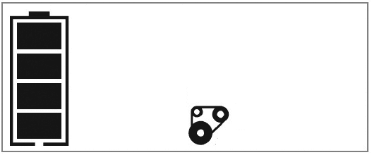 The Battery Status Icon will light solid and the Alternator Icon will flash.
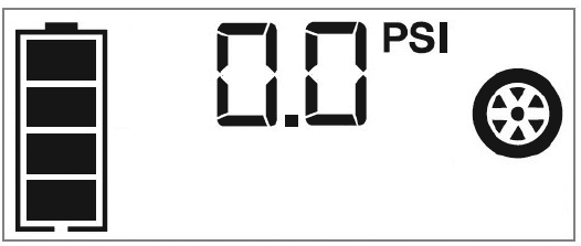 The Compressor Icon will light and the Digital Display will alternately show the flashing pre-set psi value (that was last set by the compressor pressure control buttons) and the current pressure of the item being inflated (which will light solid).
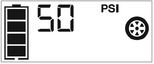 The new selected value is now stored in the unit’s memory until it is manually reset.
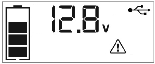 The Fault Icon will flash. The USB Ports will automatically shut down. Should this occur: