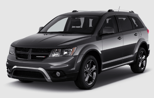
Dodge Journey 2018 SUV
FRONT VIEW
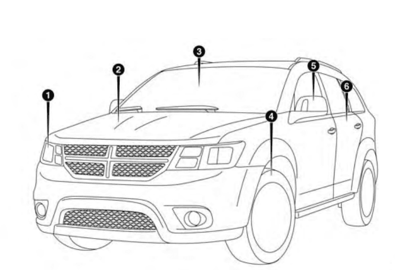
- 1Headlights
- Hood/Engine Compartment
- Windshield
- Wheels/Tires
- Exterior Mirrors
- Doors
REAR VIEW
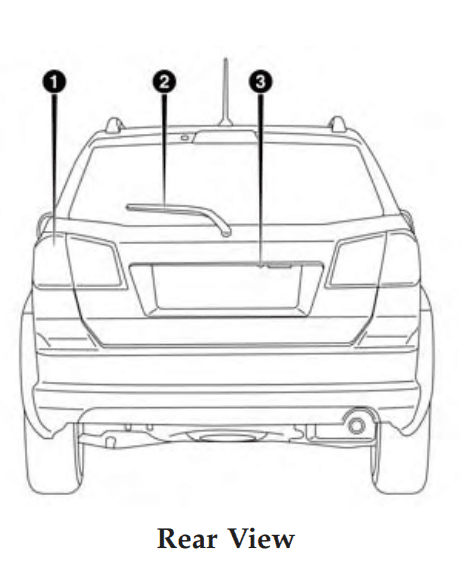
- Rear Lights
- Rear Windshield Wiper
- Liftgate
INSTRUMENT PANEL
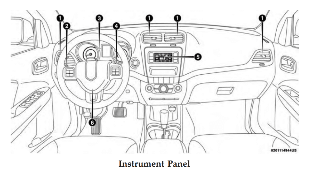
- Air Vents
- Multifunction Lever (Behind Steering Wheel)
- Instrument Cluster
- Windshield Wiper Lever (Behind Steering Wheel)
- Radio
- Steering Wheel
INTERIOR
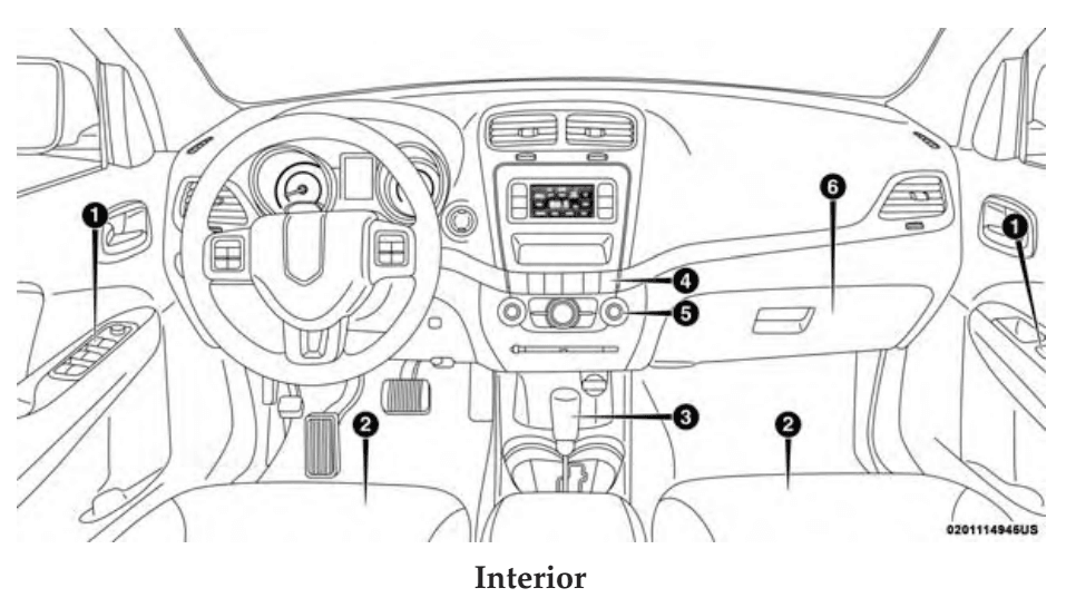
- Door Locks/Window Switches
- Seats
- Gear Selector
- Switch Panel
- Climate Controls
- Glove Compartment
KEYS
Key Fob
Your vehicle uses a keyless ignition system. The ignition system consists of a key fob with Remote Keyless Entry (RKE) and a START/STOP push button ignition system. The Remote Keyless Entry system consists of a key fob and Keyless Enter-N-Go feature if equipped.
NOTE: The key fob may not be found if it is located next to a mobile phone, laptop or other electronic device; these devices may block the key fob’s wireless signal.
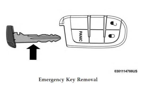
The Remote Keyless Entry (RKE) key fob and an emergency key, which stored in the rear of the key fob. The emergency key allows for entry into the vehicle should the battery in the vehicle or the key fob go dead. The emergency key is also for locking the glove compartment. You can keep the emergency key with you when valet parking. To remove the emergency key, slide the mechanical latch on the back of the key fob sideways with your thumb and then pull the key out with your other hand.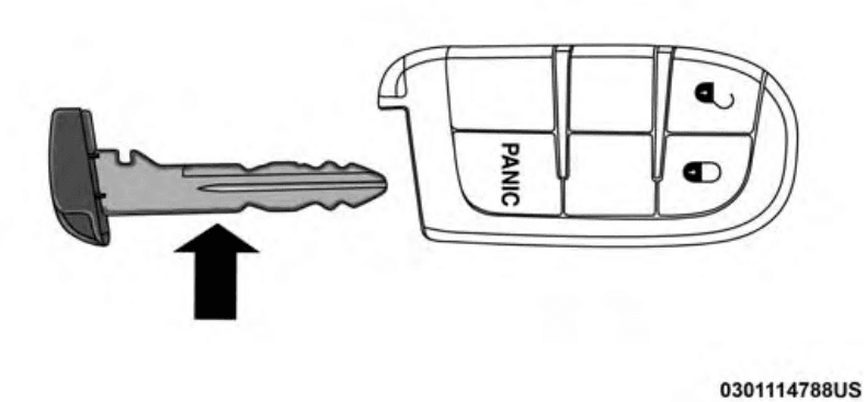
NOTE: You can insert the double-sided emergency key into the lock cylinders with either side up.
The Remote Keyless Entry system allows you to lock or unlock the doors, open the liftgate, or activate the Panic Alarm from distances up to approximately 66 ft (20 m) using a hand-held key fob with the key fob. The key fob does not need to be pointed at the vehicle to activate the system.
NOTE: Driving at speeds 5 MPH (8 km/h) and above disables the system from responding to all key fob buttons for all key fobs.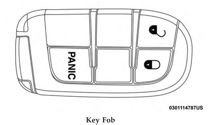
To Unlock The Doors And Liftgate
Push the interior door unlock button on the door panel. Push and release the unlock button on the key fob once to unlock the driver’s door or twice within five seconds to unlock all doors and the liftgate. All doors can be programmed to unlock on the first push of the unlock button. Refer to “Uconnect Settings” in “Multimedia” for further information. The turn signal lights will flash to acknowledge the unlock signal. The illuminated entry system will be activated.
1st Push Of Key Fob Unlock Button
This feature lets you program the system to unlock either the driver’s door or all doors on the first push of the unlock button on the key fob. To change the current setting, refer to “Uconnect Settings” in “Multimedia” for further information.
NOTE: If the vehicle is equipped with Passive Entry, refer to “Keyless Enter-N-Go — Passive Entry” located in “Doors” in “Getting To Know Your Vehicle” for further information.
Headlight Illumination On Approach
This feature activates the headlights for up to 90 seconds when the doors are unlocked with the key fob. The time for this feature is programmable on vehicles equipped through Uconnect. To change the current setting, refer to “Uconnect Settings” in “Multimedia” for further information.
To Lock The Doors And Liftgate
Push and release the lock button on the key fob to lock all doors and liftgate. The turn signal lights will flash and the horn will chirp to acknowledge the signal. Refer to “Uconnect Settings” located in “Multimedia” for further programmable information. If the vehicle is equipped with Passive Entry, refer to “Keyless Enter-N-Go — Passive Entry” located in “Doors” in “Getting To Know Your Vehicle” for further information.
Key Fob Battery Replacement
The recommended replacement battery is one CR2032 battery.
NOTE:
- Perchlorate Material — special handling may apply. See www.dtsc.ca.gov/hazardouswaste/perchlorate
- Do not touch the battery terminals that are on the back housing or the printed circuit board.
- Remove the emergency key by sliding the mechanical latch on the back of the key fob sideways with your thumb and then pull the key out with your other hand.

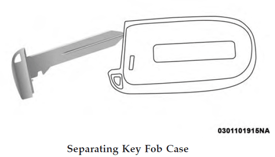
- Insert the tip of the emergency key or a #2 flat-blade screwdriver into the slot and gently pry the two halves of the key fob apart. Make sure not to damage the seal during removal.

- Remove the battery by turning the back cover over (battery facing downward) and tapping it lightly on a solid surface such as a table or similar, then replace the battery. When replacing the battery, match the + sign on the battery to the + sign on the inside of the battery clip, Removal is located on the back cover. Avoid touching the new battery with your fingers. Skin oils may cause battery deterioration. If you touch a battery, clean it with rubbing alcohol.
- To assemble the key fob case, snap the two halves together.
Programming Additional Key Fobs
Programming the key fob may be performed by an authorized dealer.
General Information
The following regulatory statement applies to all radio frequency (RF) devices equipped in this vehicle: This device complies with Part 15 of the FCC Rules and with Industry Canada license-exempt RSS standard(s). Operation is subject to the following two conditions:
- This device may not cause harmful interference, and
- This device must accept any interference received, including interference that may cause undesired operation.
NOTE: Changes or modifications not expressly approved by the party responsible for compliance could void the user’s authority to operate the equipment.
IGNITION SWITCH
Keyless Push Button Ignition
This feature allows the driver to operate the ignition with the push of a button as long as the key fob is in the passenger compartment. The Keyless Push Button Ignition has four operating positions, three of which are labeled and will illuminate when in position. The three positions are OFF, ACC, and ON/RUN. The fourth position is START. During the start, ON/RUN will illuminate.
INSTRUMENT CLUSTER

Instrument Cluster Descriptions
Tachometer
- Indicates the engine speed in revolutions per minute (RPM x 1000).
Instrument Cluster
Instrument Cluster Display
- When the appropriate conditions exist, this display shows the instrument cluster display messages. Refer to “Instrument Cluster Display” in “Getting To Know Your Instrument Panel” for further information.
Speedometer
- Indicates vehicle speed.
Fuel Gauge
- The pointer shows the level of fuel in the fuel tank when the Keyless Push Button Ignition is in the
ON/RUN position. - The fuel pump symbol points to the side of the vehicle where the fuel door is located.
Temperature Gauge
- The temperature gauge shows the engine coolant temperature. Any reading within the normal range indicates that the engine cooling system is operating satisfactorily.
- The gauge pointer will likely indicate a higher temperature when driving in hot weather, up mountain grades, or when towing a trailer. It should not be allowed to exceed the upper limits of the normal operating range.
INSTRUMENT CLUSTER DISPLAY
Your vehicle may be equipped with an instrument cluster display, which offers useful information to the driver. With the ignition in the STOP/OFF mode, opening/closing of a door will activate the display for viewing, and display the total miles, or kilometers, in the odometer. Your instrument cluster display is designed to display important information about your vehicle’s systems and features. Using a driver interactive display located on the instrument panel, your instrument cluster display can show you how systems are working and give you warnings when they are not. The steering wheel-mounted controls allow you to scroll through the main menus and submenus. You can access the specific information you want and make selections and adjustments.
Instrument Cluster Display Location And Controls
The instrument cluster display features a driver-interactive display that is located in the instrument cluster.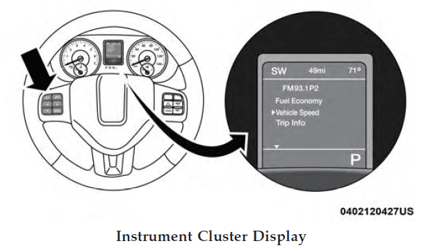
This system allows the driver to select a variety of useful information by pushing the switches mounted on the steering wheel. The menu items consist of the following:
- Radio Info
- Fuel Economy
- Vehicle Speed
- Trip Info
- Tire Pressure
- Vehicle Information
- Messages
- Turn Menu OFF
The system allows the driver to select information by pushing the following buttons mounted on the steering wheel:
- Up Arrow Button
- Push and release the up arrow button to scroll upward through the main menus and submenus.
- Down Arrow Button
- Push and release the down arrow button to scroll downward through the main menus and submenus.
- Right Arrow Button
- Push and release the right arrow button for access to the main menus or submenus. Push and hold the right arrow button for two seconds to reset features.
- BACK Button
- Push and release the BACK button to scroll back to a previous menu.
Oil Change Due
Your vehicle is equipped with an engine oil change indicator system. The “Oil Change Due” message will appear in the instrument cluster display for five seconds after a single chime has sounded to indicate the next scheduled oil change interval. The engine oil change indicator system is duty cycle based, which means the engine oil change interval may fluctuate depending on your driving style. Unless reset, this message will continue to display each time you cycle the ignition to the ON/RUN position. To turn off the message temporarily, push and release the up arrow button. To reset the oil change indicator system
(after performing the scheduled maintenance), perform the following procedure:
- Without pushing the brake pedal, push and release the ENGINE START/STOP button and cycle the ignition to the ON/RUN position (do not start the engine).
- Fully push the accelerator pedal, slowly, three times within 10 seconds.
- Without pushing the brake pedal, push and release the ENGINE START/STOP button once to return the ignition to the OFF/LOCK position.
NOTE: If the indicator message illuminates when you start the vehicle, the oil change indicator system does not reset. If necessary, repeat this procedure.
Display Menu Items
Fuel Economy
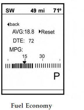
Push and release the up or down arrow button until the “Fuel Economy” displays are highlighted in the instrument cluster display and push the right arrow button. The following Fuel Economy functions will be displayed in the instrument cluster display:
- Average Fuel Economy
- Distance To Empty (DTE)
- Instantaneous Fuel Economy
Average Fuel Economy
Shows the average fuel economy since the last reset. When the fuel economy is reset, the display will read “RESET” or show dashes for two seconds. Then, the historical information will be erased, and the averaging will continue from the last fuel average reading before the reset.
Distance To Empty (DTE)
Shows the estimated distance that can be traveled with the fuel remaining in the tank. This estimated distance is determined by a weighted average of the instantaneous and average fuel economy, according to the current fuel tank level. DTE cannot be reset through the right arrow
button.
NOTE: Significant changes in driving style or vehicle loading will greatly affect the actual drivable distance of the vehicle, regardless of the DTE displayed value.
When the DTE value is less than 30 miles (48 km) estimated driving distance, the DTE display will change to a “LOW FUEL” message. This display will continue until the vehicle runs out of fuel. Adding a significant amount of fuel to the vehicle will turn off the “LOW FUEL” message and a new DTE value will display.
Instantaneous Fuel Economy
This display shows the instantaneous fuel economy MPG or L/ 100 km in bar graph form while driving. This will monitor the gas mileage in real-time as you drive and can be used to modify driving habits in order to increase fuel economy.
Vehicle Speed
Push and release the up or down arrow button until “Vehicle Speed” displays are highlighted in the instrument cluster display. Push the right arrow button to display the current speed in MPH or km/h. Pushing the right arrow button a second time will toggle the unit of measure between MPH or km/h.
NOTE: Changing the unit of measure in the Vehicle Speed menu will not change the unit of measure in the instrument cluster display.
WARNING LIGHTS AND MESSAGES
The warning/indicator lights will illuminate the instrument panel together with a dedicated message and/or acoustic signal when applicable. These indications are indicative and precautionary and as such must not be considered as exhaustive and/or alternative to the information contained in the Owner’s Manual, which you are advised to read carefully in all cases. Always refer to the information in this chapter in the event of a failure indication. All active telltales will display first if applicable. The system check menu may appear different based on equipment options and current vehicle status. Some telltales are optional and may not appear.
SAFETY FEATURES
Anti-Lock Brake System (ABS)
The Anti-Lock Brake System (ABS) provides increased vehicle stability and brake performance under most braking conditions. The system automatically prevents wheel lock and enhances vehicle control during braking. The ABS performs a self-check cycle to ensure that the ABS is working properly each time the vehicle is started and driven. During this self-check, you may hear a slight clicking sound as well as some related motor noises. ABS is activated during braking when the system detects one or more wheels begin to lock. Road conditions such as ice, snow, gravel, bumps, railroad tracks, loose debris, or
panic stops may increase the likelihood of ABS activation(s).
You also may experience the following when ABS activates:
- The ABS motor noise (it may continue to run for a short time after the stop).
- The clicking sound of solenoid valves.
- Brake pedal pulsations.
- A slight drop of the brake pedal at the end of the stop.
These are all normal characteristics of ABS. ABS is designed to function with the OEM tires. Modification may result in degraded ABS performance.
Anti-Lock Brake Warning Light
The yellow “Anti-Lock Brake Warning Light” will turn on when the ignition is turned to the ON/RUN mode and may stay on for as long as four seconds. If the “Anti-Lock Brake Warning Light” remains on or
comes on while driving, it indicates that the anti-lock portion of the brake system is not functioning and that service is required. However, the conventional brake system will continue to operate normally if the “Brake System Warning Light” is not on. If the “Anti-Lock Brake Warning Light” is on, the brake system should be serviced as soon as possible to restore the benefits of anti-lock brakes. If the “Anti-Lock Brake Warning Light” does not come on when the ignition is turned to the ON/RUN mode, have the light repaired as soon as possible.
Electronic Brake Control System
Your vehicle is equipped with an advanced Electronic Brake Control system (EBC). This system includes an Electronic Brake Force Distribution (EBD), Anti-Lock Brake System (ABS), Brake Assist System (BAS), Hill Start Assist (HSA), Traction Control System (TCS), Electronic Stability Control (ESC), and Electronic Roll Mitigation (ERM). These systems work together to enhance both vehicle stability and control in various driving conditions. Your vehicle may also be equipped with Trailer Sway Control (TSC).
Brake Assist System (BAS)
The BAS is designed to optimize the vehicle’s braking capability during emergency braking maneuvers. The system detects an emergency braking situation by sensing the rate and amount of brake application and then applying optimum pressure to the brakes. This can help reduce braking distances. The BAS complements the anti-lock brake system (ABS). Applying the brakes very quickly results in the best BAS assistance. To receive the benefit of the system, you must apply continuous braking pressure during the stopping sequence, (do not “pump” the brakes). Do not reduce brake pedal pressure unless braking is no longer desired. Once the brake pedal is released, the BAS is deactivated.
Brake System Warning Light
The red “Brake System Warning Light” will turn on when the ignition is turned to the ON/RUN mode and may stay on for as long as four seconds. If the “Brake System Warning Light” remains on or comes on while driving, it indicates that the brake system is not functioning properly and that immediate service is required. If the “Brake SystemWarning Light” does not come on when the ignition is turned to the ON/RUN mode, have the light repaired as soon as possible.
Electronic Brake Force Distribution (EBD)
This function manages the distribution of the braking torque between the front and rear axles by limiting braking pressure to the rear axle. This is done to prevent the overslip of the rear wheels to avoid vehicle instability and to prevent the rear axle from entering ABS before the front axle.
Electronic Roll Mitigation (ERM)
This system anticipates the potential for wheel lift by monitoring the driver’s steering wheel input and the speed of the vehicle. When ERM determines that the rate of change of the steering wheel angle and vehicle’s speed are sufficient to potentially cause wheel lift, it then applies the appropriate brake and may also reduce engine power to lessen the chance that wheel lift will occur. ERM can only reduce the chance of wheel lift occurring during severe or evasive driving maneuvers; it cannot prevent wheel lift due to other factors, such as road conditions, leaving the roadway, or striking objects or other vehicles.
Electronic Stability Control (ESC)
This system enhances directional control and stability of the vehicle under various driving conditions. ESC corrects for oversteering or understeering of the vehicle by applying the brake of the appropriate wheel(s) to assist in counteracting the oversteer or understeer condition. Engine power may also be reduced to help the vehicle maintain the desired path. ESC uses sensors in the vehicle to determine the vehicle path intended by the driver and compares it to the actual path of the vehicle. When the actual path does not match the intended path, ESC applies the brake of the appropriate wheel to assist in counteracting the oversteer or understeer condition.
- Oversteer — when the vehicle is turning more than appropriate for the steering wheel position.
- Understeer — when the vehicle is turning less than appropriate for the steering wheel position.
The “ESC Activation/Malfunction Indicator Light” located in the instrument cluster will start to flash as soon as the ESC system becomes active. The “ESC Activation/Malfunction Indicator Light” also flashes when the TCS is active. If the “ESC Activation/Malfunction Indicator Light” begins to flash during acceleration, ease up on the accelerator and apply as little throttle as possible. Be sure to adapt your speed and driving to the prevailing road conditions.
ESC Operating Modes
NOTE: Depending upon the model and mode of operation, the ESC systems may have multiple operating modes.
ESC On
This is the normal operating mode for the ESC. Whenever the vehicle is started, the ESC system will be in this mode. This mode should be used for most driving conditions. Alternate ESC modes should only be used for specific reasons as noted in the following paragraphs.
Partial Off
The “Partial Off” mode is intended for times when a more spirited driving experience is desired. This mode may modify TCS and ESC thresholds for activation, which allows for more wheel spin than normally allowed. This mode may be useful if the vehicle becomes stuck. To enter the “Partial Off” mode, momentarily push the “ESC Off” switch and the “ESC Off Indicator Light” will illuminate. To turn the ESC on again, momentarily push the “ESC Off” switch, and the “ESC Off Indicator Light” will turn off.
Summary Of Recommendations For Restraining Children In Vehicles
| Child Size, Height, Weight Or Age | Recommended Type Of Child Restraint | |
| Infants and Toddlers | Children who are two years old or younger and who have not reached the height or weight limits of their child restraint | Either an Infant Carrier or a Convert- ible Child Restraint, facing rearward in the rear seat of the vehicle |
| Small Children | Children who are at least two years old or who have outgrown the height or weight limit of their rear-facing child restraint | Forward-facing child Restraint with a five-point Harness, facing forward in the rear seat of the vehicle |
| Larger Children | Children who have outgrown their forward-facing child restraint, but are too small to properly fit the vehicle’s seat belt | Belt-Positioning Booster Seat and the vehicle seat belt, seated in the rear seat of the vehicle |
| Children Too Large for Child Restraints | Children 12 years old or younger, who have outgrown the height or weight limit of their booster seat | Vehicle Seat Belt, seated in the rear seat of the vehicle |
Infant And Child Restraints
Safety experts recommend that children ride rear-facing in the vehicle until they are two years old or until they reach either the height or weight limit of their rear-facing child restraint. Two types of child restraints can be used rear-facing: infant carriers and convertible child seats. The infant carrier is only used rear-facing in the vehicle. It is recommended for children from birth until they reach the weight or height limit of the infant carrier. Convertible child seats can be used either rear-facing or forward-facing
in the vehicle. Convertible child seats often have a higher weight limit in the rear-facing direction than infant carriers do, so they can be used rear-facing by children who have outgrown their infant carrier but are still less than at least two years old. Children should remain rear-facing until they reach the highest weight or height allowed by their convertible child seat.
Recommendations For Attaching Child Restraints
| Restraint Type | Combined Weight of the Child + Child Restraint | Use Any Attachment Method Shown With An “X” Below | |||
| LATCH – Lower Anchors Only | Seat Belt Only | LATCH – Lower Anchors + Top Tether Anchor | Seat Belt + Top Tether Anchor | ||
| Rear-Facing Child Restraint | Up to 65 lbs (29.5 kg) | X | X | ||
| Rear-Facing Child Restraint | More than 65 lbs (29.5 kg) | X | |||
| Forward-Facing Child Restraint | Up to 65 lbs (29.5 kg) | X | X | ||
| Forward-Facing Child Restraint | More than 65 lbs (29.5 kg) | X | |||
For more manuals by Dodge, visit ManualsLibraryy
Dodge Journey 2018 SUV-FAQs
Where can I get a replacement owner’s manual for my Dodge Journey?
You can purchase a replacement manual from your local Dodge dealership’s parts department or order it online. Alternatively, you may find hardcopy versions from third-party vendors or marketplaces like eBay and Craigslist.
What is the normal coolant temperature for a 2018 Dodge Journey?
The engine’s normal coolant temperature ranges between 195°F to 220°F (90°C). If the temperature gauge enters the red zone, stop the vehicle immediately to prevent engine damage.
Is coolant the same as A/C refrigerant?
No, they serve different purposes:
1. Coolant (a mix of 50% water and 50% antifreeze) regulates the engine’s temperature to prevent overheating.
2. Refrigerant is part of the A/C system, used to cool the cabin by absorbing heat.
What is the difference between an owner’s manual and a service manual?
1. The owner’s manual provides basic instructions on how to use and maintain the vehicle.
2. The service manual includes detailed repair, maintenance, and troubleshooting information for mechanics and professionals.
Is the Dodge Journey expensive to maintain?
The average annual maintenance cost for a Dodge Journey is $562, though costs may vary based on age, mileage, and location.
How many speakers does the 2018 Dodge Journey have?
The standard audio system includes six speakers. The Journey GT trim comes with six premium Alpine speakers, a subwoofer, and a 368-watt amplifier.
What size battery does the 2018 Dodge Journey use?
The recommended battery is a DieHard Silver – Group Size 26, with 525 CCA (Cold Cranking Amps), 655 CA (Cranking Amps), and a 60-minute reserve capacity.
Does the 2018 Dodge Journey have Bluetooth?
Yes, the Radio 4.3 S system includes a 4.3-inch touchscreen display, SiriusXM® All Access Package, and Uconnect® Voice Command with Bluetooth®.


