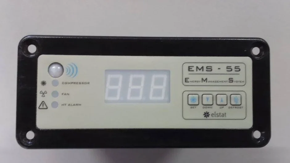
Elstat EMS 55 Advanced Controller
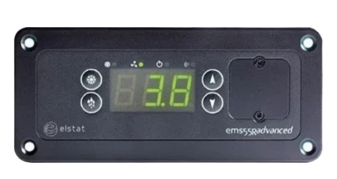
What is the EMS55advanced?
The EMS55 series is for use with open front (OFC) or glass door (GDC ) coolers, offering energy savings and guaranteed product temperatures.
Unlike mechanical thermostats, the ems self-learning technology ensures the product is at the optimum serving temperature required by the customer from the moment the outlet opens.
The ems55 series is available with an integrated motion sensor – ems55advanced, and without an integrated motion sensor – ems55Radvanced
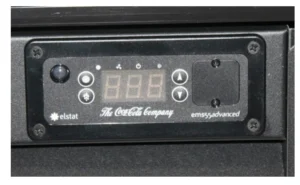
Example ems55advanced pictured below – with integrated motion sensor
Example ems55Radvanced pictured below – with remote motion sensor
The EMS55 series with the suitable accessories also provides the following functionality.

The ems55 series controllers switch the following cooler components:

ems55 series controllers
ems55 series controllers have an IP (ingress protection) rating of IPX5.
An appropriate level of protection must be given for the effects of water ingress due to condensation, product spillage, and so on.

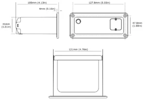
EMS55 series controllers are designed for panel mounting and are secured using four self-tapping screws in the screw holes at each corner of the fascia.
Dimensions are shown in the following diagram:
Water ingress – advisory information for FMEA analysis
Elstat products have been designed to minimise any risks associated with water ingress and all controllers are IPX5 certified.
The OEM or installer is responsible to ensure that local/country laws and regulatory requirements are met.
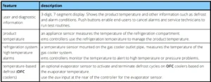
ems55 user interface
The user interfaces of the ems55advanced the ems55Radvanced are as follows:

LED indicators:


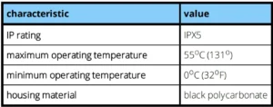
Environmental ratings
The table below details the general characteristics of ems55 series controllers.
ems55 series relay ratings
The table below details the relay ratings of ems55advanced and ems55Radvanced controllers.

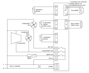
ems55advanced and ems55Radvanced wiring diagram
The wiring diagrams for the EMS55Advanced and EMS55RAdvanced are shown below.
How to mount ems55 series controllers
ems55 series controllers are designed to be mounted horizontally. Ingress protection (IP) rating of IPX5 applies to ems55 controllers mounted in the correction orientation only, as shown below.
Caution: mounting ems55 series ems controllers vertically may result in water ingress as the IP rating of IPX5 applies only if mounted horizontally, in addition, in correct installation may result in the following conditions:
- if mounted vertically with the motion sensor close to floor, the motion sensor not be able to detect motion effectively.
- if mounted vertically with parameter programming port close to the floor, any water ingress may occur.
- if mounted too close the floor, water ingress may occur at the mains or line voltage terminals.
Cable routing to the ems controller is critical as water can trace or follow the cable downwards.
Therefore, immediately prior to the connection to the controller, a drip-loop must be formed in all wiring as shown below.

Attention:
- Cable routing looms must not be secured to hot pipes or vibrating components.
- Secure cable routing looms with clips wherever possible.
How to mount EMS55 series controllers.
The ems55 series controllers have an IP (ingress protection) rating of IPX5.
An appropriate level of protection must be given for the effects of water ingress due to condensation, product spillage, and so on.
Caution: The ems55 series controllers must not be exposed to temperatures greater than 55°C (131°F) or lower than 0°C (32°F).
ems55 series controllers are designed for panel mounting and are secured using four countersunk self-tapping screws. The aperture and screw pitch dimensions are shown below.

Temperature input ranges
The table below shows the temperature input ranges of the ems55 series controllers for each sensor type.

Note:
- The NTC (negative temperature coefficient) thermistor from elstat is rated at: -35ºC to 125ºC (-31ºF to 257ºF).
How to mount the appliance sensor
The appliance sensor measures air temperature of the refrigerated compartment by measuring the return air temperature.
The diagram below shows the recommended position of the appliance sensor. The appliance sensor measures the air temperature after the air has been drawn over the products. The return air provides a close approximation of the product temperature.
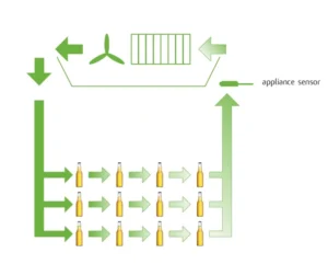
To measure the return air temperature, secure the sensor to allow air to flow over the sensor head.
The sensor head should be placed at a right-angle to the air flow and secured using a P-clip.
The P-clip should not completely cover the sensor head or the sensor will not function correctly.
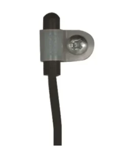
Caution:
- The sensor head is fragile and can easily be damaged. Using cable ties to secure the sensor head or sensor cable is not recommended and invalidates the warranty.
To help place the appliance sensor, the parameter calibration 1 (CA1) defines an offset temperature.
- See “calibration 1 (CA1)” on page 69
How to mount the condenser sensor
This sensor measures the temperature of the refrigeration system. Excessive condenser temperature is usually due to poor preventive maintenance, i.e poorly cleaned condenser, or condenser fan failure.
Condenser sensor
ems controllers can generate alarms if the refrigeration system temperature rises too high.
The value of the high temperature is set by measuring the refrigeration system temperature, when the condenser is approximately 75% blocked. The temperature is then set as the value of the condenser high temperature (Ht) parameter.
- See “condenser high temperature (Ht)” on page 76
For example, fix using a metal pipe clip or direct fitting, as shown below.
Elstat can supply pipe clips for 6-8mm and 8-10mm pipes.

Caution:
- Do not use cable ties.
The head of the sensor is fragile and can be easily damaged. Using cable ties to secure the sensor head or sensor cable invalidates the warranty. - Do not attach sensor cables to hot pipes or allow the sensor cables to come into contact with hot pipes.
How to mount the evaporator sensor
The evaporator sensor measures the temperature of the evaporator. ems controllers use the temperature of the evaporator to activate and terminate defrost cycles.
The evaporator sensor should be placed in the immediate proximity of the evaporator. Mount the sensor head inside the evaporator cooling fins, as shown below.
The sensor head must be mounted securely to prevent being dislodged due to vibration.

For coolers fitted with a defrost heater, the evaporator sensor should be placed as far away as possible from the heating element, i.e. at the opposite end of the evaporator.
If the evaporator sensor measures the localized heating from the heating element, defrost cycles will terminate before the whole evaporator has had the opportunity to defrost.
Caution:
- Do not use cable ties.
The head of the sensor is fragile and can be easily damaged. Using cable ties to secure the sensor head, or sensor cable, invalidates the warranty.
Door switch
Door switches are used to detect door openings. Door switches are SELV (safety extra low voltage) components that are able to create an open and closed circuit.
The enhanced door switch, and activator, are SELV (safety extra low voltage) components, over-moulded for strengthened physical protection and resistance to water ingress, and create an open and closed circuit.
Enhanced door switches must be used with enhanced activators.
Enhanced door switches are available in various lengths.

How to mount the door switch
Door switches are usually mounted with the door switch on the cooler and the activator on the door.
Door switches and activators must be fixed using counter sunk screws or bolts with the following characteristics:
- Head: countersunk head maximum diameter 5.0mm (0.24in).
- Thread: maximum diameter 3.0mm (0.16in).
The screws must be tightened to a maximum torque of 0.5Nm (0.37lbfft).
Caution:
- Door switches and activators supplied by elstat must not be installed using rivets. Using rivets invalidates the warranty.

The alignment of the door switch and activator is critical for the correct operation of the door switch. The following table details alignment tolerances.

![]()
The diagram shows the horizontal, vertical, and gap alignment between the door switch and the activator for open and closed doors.

how to mount the enhanced door switch
Door switches are usually mounted with the door switch on the cooler and the activator on the door. Door switches and activators must be fixed using counter sunk screws or bolts with the following characteristics:
- Head: countersunk head maximum diameter 6.0mm (0.236in) and minimum diameter 5.0mm (0.196 in).
- Thread: maximum diameter 3.0mm (0.118in).
The screws must be tightened to a maximum torque of 0.5Nm (0.37lbfft).
Caution:
Door switch kits supplied by elstat must not be installed using rivets. Using rivets invalidates the warranty.
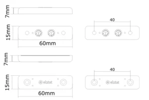
The alignment of the door switch and activator is critical for the correct operation of the door switch. The table below details the alignment tolerances.

![]()
The diagram below shows the horizontal, vertical, and gap alignment between the door switch and the activator for open and closed doors.
For best results, elstat recommends that enhanced door switches are used with enhanced door switch activators. Performance will not be guaranteed if:

- Enhanced activators are paired with current door switches
- Enhanced door switches are paired with current activators.
Enhanced door switches and enhanced activators must be used as a set.
how to mount door switches on double-door coolers
For double-door coolers, two door switches must be connected in series.
Connect two door switches in series as follows:
- Remove the two wires from one of the connectors. Be careful not to damage the terminals.
- Remove the white wire from the second connector. Again, be careful not to damage the terminal.
- Insert the white wire of the first cable into the connector of the second cable ensuring that the terminal is in the correct orientation.
- Connect the red wire from the first cable and the white wire from the second cable together using a butt splice or similar.
The image below shows two door switches connected in series.

Troubleshooting
The following table shows the display for alarm conditions. EMS controllers can be programmed to sound a buzzer with alarm conditions.
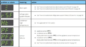
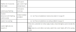
How to check that ems controllers are working correctly
During the ready mode, the ems controller displays the appliance sensor temperature, such as 4.0, or the word USE as shown below.
The option to display the temperature or the word USE is set by the display (dIS ) parameter.
Follow the chart to ensure that the ems controller is working correctly in the ready mode for coolers with door switches fitted.

For information about the display (dIS) parameter:
- See “display (dIS)” on page 72
How to troubleshoot condenser high temperature (Ht) alarms
Condenser high temperature (Ht) alert to problems with the refrigeration system such as a blocked condenser or faulty condenser fan.
Note: this alarm is not applicable to CO2 coolers and the ems55advanced CO2.
For information about the condenser high temperature (Ht) parameter:
- See “condenser high temperature (Ht)” on page 76
Follow the chart to troubleshoot condenser high temperature (Ht) alarms.
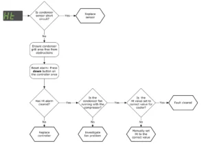
how to troubleshoot door alarms (door switch fitted)
Door open alarms are triggered if the cooler door is left open for longer than the time defined by the alarm delay (Ad) parameter.
If the door is closed, and a door open alarm is registered, this may indicate problems with the cooler door or the door switch.
For information about the alarm delay (Ad) parameter:
- See “alarm delay (Ad)” on page 67
Follow the chart to troubleshoot door open alarms on coolers with a door switch.
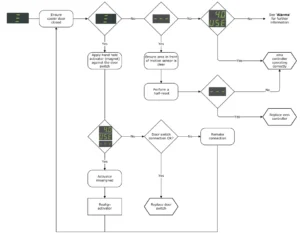
how to troubleshoot door alarms (no door switch fitted)
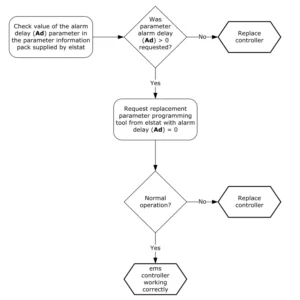
Door alarms with coolers without a door switch fitted usually indicates that the ems controller has an incorrect parameter set.
For information about the alarm delay (Ad) parameter:
- See “alarm delay (Ad)” on page 67
Follow the chart to troubleshoot door open alarms on coolers without a door switch fitted.
how to troubleshoot motion sensor alarms
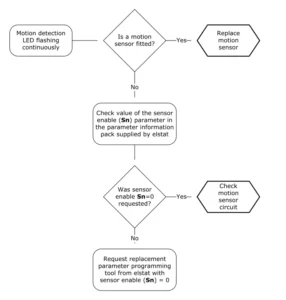
The motion detection LED flashes to indicate that movement has been detected.
However, a motion sensor LED flashing continuously may indicate that the motion sensor is faulty or, if a motion sensor is not fitted, that the parameter settings are incorrect.
Note:
- The ems controller stays in the ready mode if the motion detection LED is flashing continuously.
For information about the motion sensor enable (Sn) parameter:
- See “motion sensor enable (Sn)” on page 79
Follow the chart to troubleshoot problems with the motion sensor.
how to troubleshoot refrigeration system failure (rSF) alarms
Refrigeration system failure (rSF) alarms trigger if the set point (SP) temperature is not reached within the time defined by the compressor runtime (Ct) parameter.
For information about the set point and compressor run time parameters:
- See “refrigeration system failure (Ct)” on page 70
- See “set point (SPC or SPF)” on page 80
Follow the chart to troubleshoot refrigeration system failures.

how to troubleshoot temperature sensor alarms
ems controllers manage sensor failures as follows:
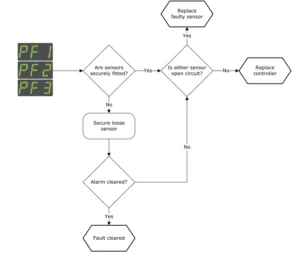
- PF1 alarms: ems controllers stop running the compressor and then waits 60 seconds before re-starting (switch off and then switch on). If the fault continues, the ems controller repeats and continues the cycle until the fault corrected.
- PF2 alarms: ems controllers continue running the compressor. ems controllers alternate the display between PF2and the appliance sensor temperature indicating a fault.
- PF2 alarms: ems55advanced CO2 controllers continue to run the compressor normally and alternate the display PF2 and the gas cooler sensor temperature indicating a fault.
- PF3 alarms: ems controllers continue to run the compressor normally and alternate the display PF3 and the appliance sensor temperature.
Sensor faults may also be identified by using the input test within the test routine:
- See “how to run the test routine (tst)” on page 40
Follow the chart to troubleshoot problems with the appliance sensor, condenser sensor, evaporator sensor or gas cooler sensor.
how to troubleshoot problems with freeze-up protection (888)
Problems with freeze-up protection may occur if the ambient temperature falls below 0°C (32°F) or if the appliance sensor fails.
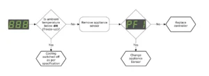
For information about the freeze-up protection (dtt) parameter:
- See “freeze-up protection (dtt)” on page 74
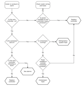
how to troubleshoot not cooling problems
Follow the chart below to troubleshoot problems of the cooler not cooling, i.e. the cooler or product is warm.
For more manuals by Blogs, visit ManualsLibraryy
Elstat EMS 55 Advanced Controller- FAQs
What is the Elstat EMS 55 Advanced Controller used for?
The EMS 55 is a refrigeration controller designed to manage temperature, defrost cycles, and energy-saving functions in commercial fridges and freezers.
How do I set the temperature on the Elstat EMS 55?
Press the SET button, use the UP or DOWN arrows to adjust the desired temperature, and press SET again to confirm. The display will return to the main screen after a few seconds.
What does the display show on the EMS 55 controller?
The screen normally shows the current cabinet temperature. During setup or defrost, it may display symbols or error codes that indicate the controller’s status.
How can I start or stop a manual defrost cycle?
Press and hold the DEFROST button for a few seconds until the defrost indicator appears. The controller will automatically stop the defrost cycle when complete.
What should I do if an error code appears on the display?
Error codes indicate issues such as sensor faults, high temperature, or power interruptions. Check the sensor connections and wiring, then refer to the user guide for the meaning of each specific code.
How does the energy-saving function work on the EMS 55?
The energy-saving (ECO) mode reduces compressor run time during off-peak hours or when the door is closed for long periods, helping to lower energy use without affecting performance.
Can I lock the keypad to prevent unwanted changes?
Yes. To lock or unlock the keypad, hold the UP and DOWN buttons together for several seconds until the lock symbol appears or disappears on the screen.
How do I reset the Elstat EMS 55 to factory settings?
Turn off the power, then press and hold the SET and DOWN buttons while powering the unit back on. Release the buttons when the display flashes—this restores the default factory configuration.

