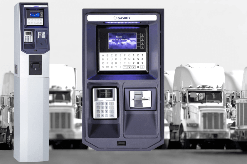
Gasboy Islander Prime Fleet Fuel Management System
Introduction
General
- This manual describes the Islander Prime Fuel Island Controller, which is part of the ForeHB solution. It provides a general description of the product, a detailed description of the modules, as well as installation and maintenance guidelines.
Solution Description
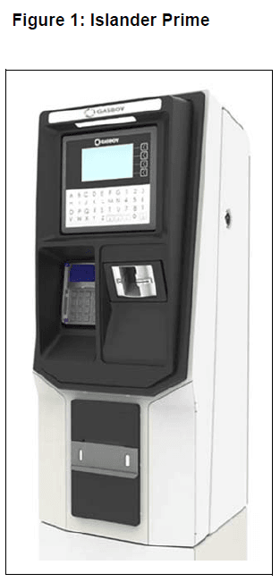
- Gasboy®’s end-to-end ForeHB homebase fleet fueling solution extends from the station to the head office, giving fleet managers the power and flexibility to monitor fuel levels and authorize fueling activity. All site activity is controlled using Gasboy’s innovative Islander Prime Fuel Island Controller, which is an all-in-one, weather-resistant cabinet that provides a complete forecourt island solution. Islander Prime is a core component of the ForeHB solution for homebase refueling and provides automation and control over all forecourt equipment at the station, such as:
- Automatic Vehicle Identification System
- Transaction data storage
- Control over dispensers
- Reads ATGs
- Islander Prime’s ruggedized pedestal and user-friendly interface increase fleet operating margins, provide efficient vehicle refueling, offer real-time information on fuel utilization, prevent fuel loss and misuse, and give homebase managers better control over inventory and delivery. The Islander Prime is equipped with the following components:
- Embedded Linux controller
- Or PAY1000 Payment Terminal
- Communication interface modules mechanical/electronic/mixed
- Optional outdoor receipt printer
- Modular software licensing allowing different pricing by number of pumps, ATG, Fuel Point PLUS integration
- Optional EMV card reader and PIN pad
- nOrCU full station automation
- WiFi and/or cellular connectivity with the addition of an optional modem add-on

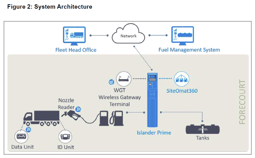
System Architecture
- Figure 2 shows a basic diagram of the ForeHB system architecture:

System Overview
General
- This section provides a detailed description of the Islander Prime system, as well as the available configurations, system specifications, and communication standards.
System Description
- The following describes the modules that make up the Islander Prime Fuel Island Controller. Islander Prime is an innovative controller that enables refueling in homebase stations for fleets of authorized vehicles or drivers. Islander Prime electronically locks all dispensers and pumps, ensuring only authorized vehicles receive the required fuel. The system also ensures accurate recording of each transaction.
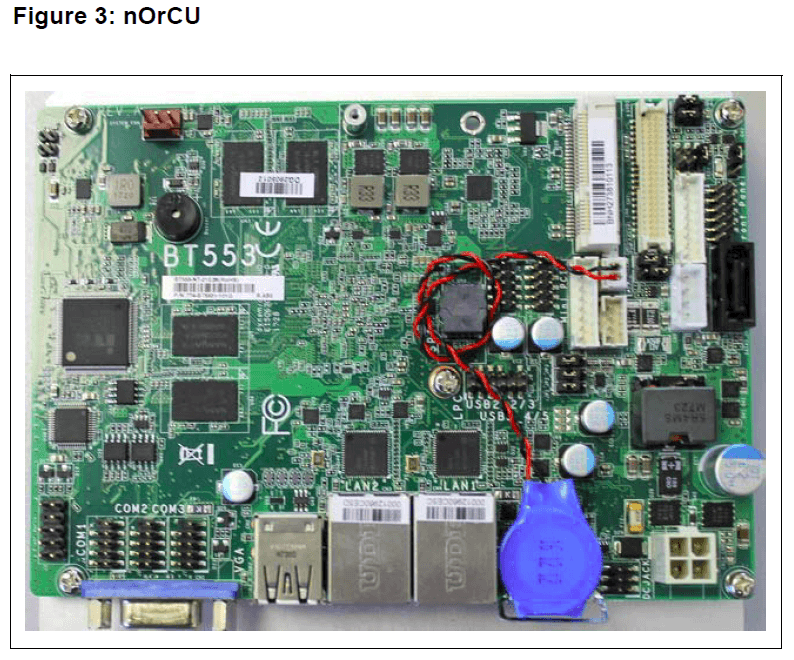
- The heart of the ForeHB solution is the SiteOmat automation software. SiteOmat runs on an embedded operating system on the nOrCU (Gasboy Controller Unit). nOrCU is an embedded hardware platform designed to withstand the harsh gas station environment. It uses a solid-state Flash disk and RTC (Time Clock) with back up, along with surge suppressors for transient and noise immunity. The system also includes power fail recovery mechanisms.
Remote Web Access
- Remote Web-based capabilities for monitoring, management and maintenance are available. A standard PC with an Internet browser is used for management of the site either locally or remotely (secured). A software license is provided with the Islander Prime system to access these features.
Islander Prime Structure
- The following describes the components that are part of the Islander Prime structure, including their location and configuration.
Main Components
- The following provides a description of Islander Prime’s main sub-units.
Gasboy Controller Unit (nOrCU)The
- Gasboy Controller Unit (nOrCU) is a complete forecourt controller with its own embedded operating system. The unit consists of an embedded hardware platform with a solid state flash storage, Real real-time clock (RTC) with a backup. nOrCU features two separate and isolated networks (TCP/IP over Ethernet). One network links the Islander Prime system components. The second network is intended for external remote communication (Head Office, third-party systems). This network is protected by SSL security. nOrCU includes a built-in server for Web access through an Internet browser

G2 Panel Printer
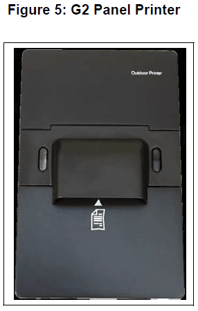
- Islander Prime includes an optional printer for receipt printouts as well as data output. The printer is linked to the central payment terminal that sends to it the transaction data for printout.
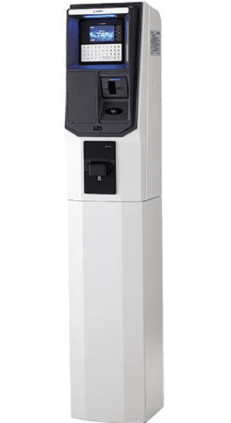
- The thermal printer is installed at the center of the Islander Prime pedestal door. It includes an integrated paper cutter, paper feeder, paper spool, and an “End of paper” warning sensor.

Communication Interfaces
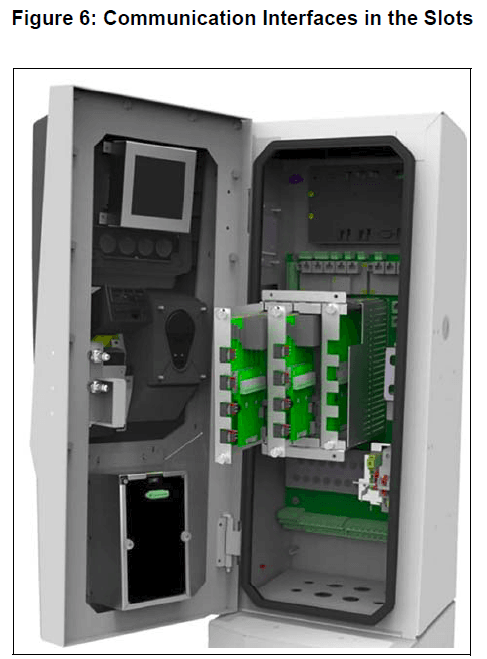
- Islander Prime contains three slots for the various optional communication interfaces (1, 2, and 3). There are two types of communication interfaces that can be inserted into the slots: mechanical and electronic. Slots 1 and 2 can house both mechanical and electronic communication interfaces, and slot 3 can only house an electronic communication interface. The mechanical interfaces contain up to four onboard bypass switches.

Internal Configuration
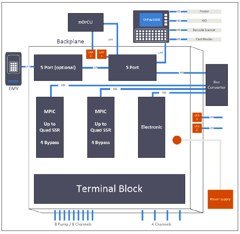
- The following is an example of the Islander Prime internal configuration (see Figure 7).
- Figure 7: Internal Configuration Diagram

Housing
- The Islander Prime system enclosure is made of a metal cabinet with plastic panels in the form of a pedestal. The enclosure is weather resistant in order to sustain the harsh environment of a homebase Station. It is also waterproof, with a certified Ingress Protection (IP) rating of IP54. The payment panel of the Islander Prime is made of rugged plastic. The devices in the front panel are sealed to prevent humidity and dust penetration.
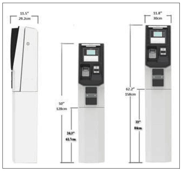
- Note: Do not pressure wash the Islander Prime. Islander Prime pedestal is locked by key for safety and security. The key should be kept in a secure and safe place. The following displays the Islander Prime dimensions (see Figure 8):
- Figure 8: Islander Prime Dimensions

Preliminary Guidelines
Precautions and Safety Notes
- Before installing or servicing equipment, carefully observe the warnings and precautions provided at the beginning of this manual
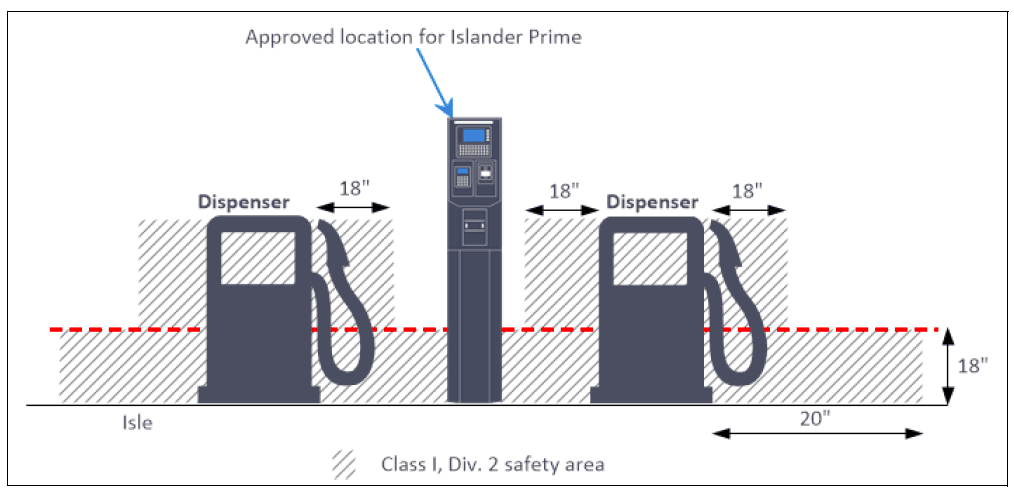
- Install Islander Prime in an area in accordance with the safety restrictions (see Figure 9).
- Figure 9: Installation Cont

Connections
- All connections to Islander Prime must be performed to the terminal block and to the Ethernet port located at the bottom of the Islander Prime pedestal (see Figure 10).
- Figure 10: Terminal Block, Power, and LAN Connections (8 Pumps)

- The required connections are as follows:
- Dispenser wiring connections
- Pulser (Low Voltage)
- In Use signal (High voltage)
- Valve (High voltage)
- Communications
- RS-232/LAN to TLG console to fuel tank
- RS-485 for Gasboy peripheral device
- Pump communication line (e.g., Current Loop, RS-485, Tokheim, RS-422)
- Mains AC Power and Ground
- LAN connection
- ETH1 for technician and maintenance
- ETH2 secured WAN
Conduits
- The installation of Islander Prime requires preparing the cable layout in the homebase station in advance. This procedure consists of installing conduits within the island, inserting the proper cables, and setting the power equipment and sensors
Requirements
- The installation of Islander Prime in the island requires digging and setting several conduits in the station ground. The conduits are required for the routing and protection of the different types of cables used in a homebase station with Islander Prime. In sites where the infrastructure is already set up, you can use the existing conduits only if they meet the requirements defined below.
Conduits must comply with the following requirements:
- All conduits must be made and installed according to local regulations.
- High-voltage AC and low-voltage DC must NOT be combined in a common conduit, junction box, or wire trough.
- RS-485 or LAN communication must not exceed 330 feet (100 m). Cables must be inserted in a separate low voltage conduit, away from AC wires. The communication range can be extended using third-party devices.
- RS-232 communication must not exceed 50 feet (15 m). RS-232 communication shielded cable must be inserted in a separate low voltage conduit, away from AC wires. The communication range can be extended using third-party devices.

Layout
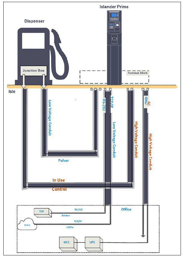
- Four conduits can be inserted in Islander Prime, each carrying specific wires (see Table 3).
- The following is a diagram of the conduit layout for Islander Prime using a mechanical pump (see Figure 12):
- Figure 12: Conduit Layout for Mechanical Pump

Installation
Installation Guidelines
- Installation procedures and requirements depend on the specific fuel dispenser models and the site layout. Therefore, use the information in this section to develop installation plans for each specific installation. Since installation requirements vary from case to case, no installation hardware is supplied by the equipment manufacturer, and installation planners must develop their own requirements.
- The customer should provide an installation plan designed by an authorized engineer. This plan design should reflect the existing electric infrastructure of the site
Installing the Pedestal Base
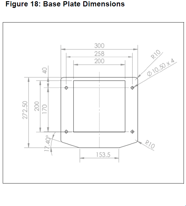
- The Islander Prime pedestal is mounted in the homebase station on a base plate that is fastened to the homebase station’s concrete floor (see Figure 18, Table 6). The upper side of the base plate includes four holding screws set in the homebase station concrete floor.

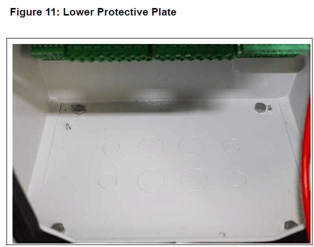
Sealing Conduits
- The conduits shall be sealed in accordance with NFPA requirements and local regulations to prevent the passage of gases through conduits, cables and conductors. The fittings are required wherever volatile liquids or gases are present in the surroundings.
- Note: Install the seal under the barrier plate with the threaded end protruding through the knockout opening.
Installing Options
Islander Prime can be provided in a number of configurations that include a variety of optional add-ons. The following optional add-ons are available:
- Barcode reader
- HID Reader
- Card reader
- Cellular modem
- Receipt printer
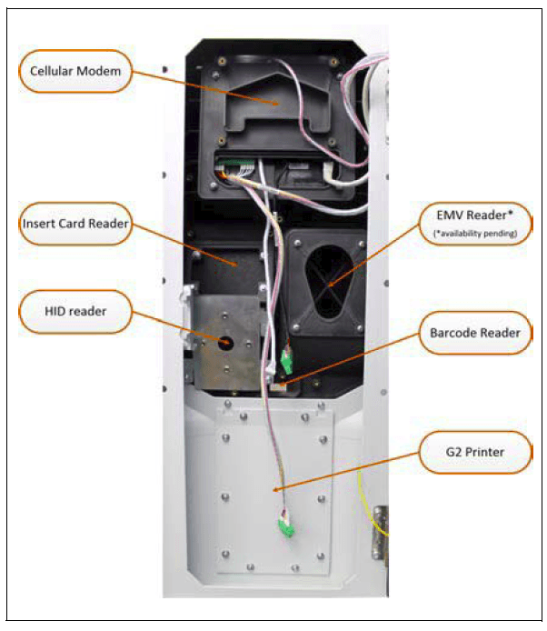
- Depending upon customer requirements, the Islander Prime may be delivered pre-assembled with all add-ons installed offsite, or it may be delivered empty, with all openings on the front of the pole covered by removable panels (see Figure 21). If the add-ons are to be assembled on site, the panels are removed as needed to install each add-on. Installation directions for each add-on are detailed below.
- Figure 21: Islander Prime Pole Door

HID Reader Installation
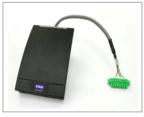
- The HID Reader (P/N M09680B134) is provided alone, without an assembly kit; it is installed using components already in the Islander Prime pole door (see Figure 29).
- Figure 26: HID Reader

To install an HID Reader in the Islander Prime, proceed as follows:
- Remove the screws affixing the HID Bracket to the Islander Prime pole door.
- Remove the back plate from the HID Reader.
- Fasten the HID Reader back plate to the HID Bracket using the flat head screws provided in the installation kit as follows (see Figure 27).
Installing Communication Interfaces
- The Islander Prime pedestal pole has three slots in which communication interface cards can be added. Each communication interface card is embedded into a blade, which slides into the slot. Slot 1 and Slot 2 can support either mechanical or electronic interfaces, and Slot 3 supports only electronic interfaces. Detailed below are instructions on how to insert communication interface blades into the slots, followed by wiring procedures for each specific type of interface.
- The wiring is performed in the Islander Prime terminal block only. The wires should be pulled from the conduits that protrude from the installation base or in the opposite direction, from the terminal block to the device in the homebase station.
Mechanical Dispenser Connections
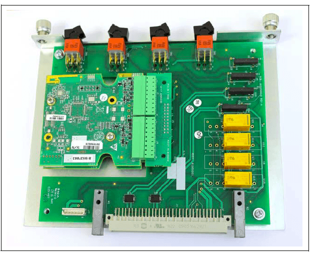
- Mechanical dispenser interfaces (see Figure 46) may be installed in either Slot 1 or Slot 2 of the Islander Prime. The following describes the required wiring connections between the mechanical dispenser interface and Islander Prime.
- Figure 46: Mechanical Dispenser Interface

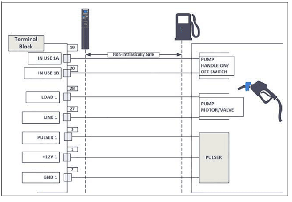
- The following is a detailed wiring diagram between the Islander Prime terminal block and the pump components (see Figure 47):
- Figure 47: Mechanical Dispenser Wiring Diagram

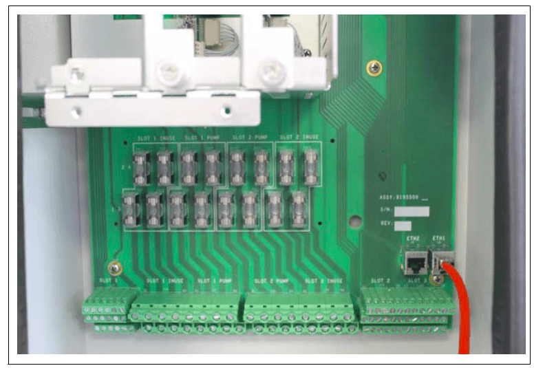
- Fuses
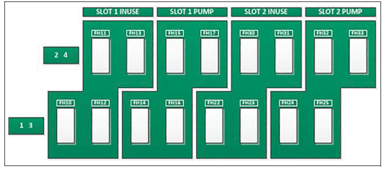
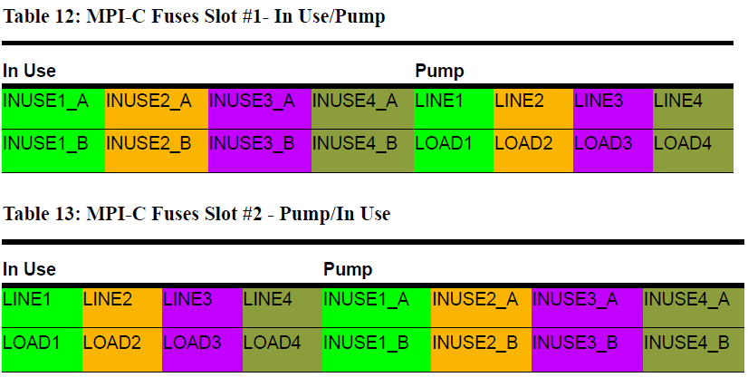
- Mechanical pumps are supplied with power via fuses located below the pump slots (see Figure 48, Table 12, Table 13):
- Figure 48: MPI-C Fuses Diagram


For more manuals by Gasboy visit, ManualsLibraryy
Gasboy Islander Prime Fleet Fuel Management System-FAQs
How does a fuel management system work?
Fuel management systems monitor and control fuel usage. Card-based systems track transactions using driver PINs and fuel cards, then generate reports based on consumption per vehicle or driver.
What warranty does the Gasboy Islander Prime come with?
Gasboy provides a limited warranty that covers parts and labor. Field-installed kits are covered for 12 months from installation or 24 months from the original invoice date—whichever comes first.
What are the main functions of a fuel system?
A fuel system stores fuel, delivers it to the engine, mixes it with air for combustion, regulates flow and pressure, and filters out impurities to ensure efficient engine performance.
What is a fleet vehicle warranty?
A fleet warranty is a manufacturer’s commitment to repair or replace parts of fleet vehicles within a set time frame or mileage limit, under specific terms and conditions.
Who manufactures Gasboy systems?
Gasboy was acquired by Danaher Corporation in 2002 and became part of Gilbarco. In 2016, it joined Fortive Corporation after a company spin-off.
Is the fuel system covered under warranty?
Yes, fuel system components like fuel pumps are usually covered under the vehicle manufacturer’s warranty if they fail due to material or workmanship defects within the warranty period.
What sensor monitors fuel levels?
Fuel level sensors (or fuel gauges) measure and report how much fuel remains in a tank, helping operators monitor usage and know when to refill.
How does a fuel system supply power to the engine?
Fuel is stored in the tank and delivered to the engine intake, where it mixes with air, is atomized, and ignited. This process creates energy that powers the vehicle.
How much does it cost to replace a fuel filter?
Replacing a fuel filter typically costs between $70 and $150, including labor. Regular replacement helps maintain fuel system health and engine efficiency.

