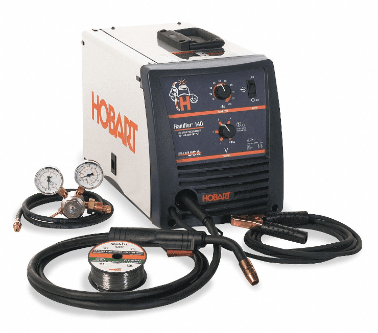
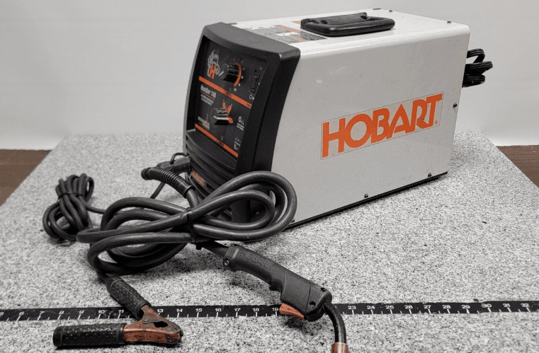
Hobart Handler 140 Welder Machine
Symbols And Definitions

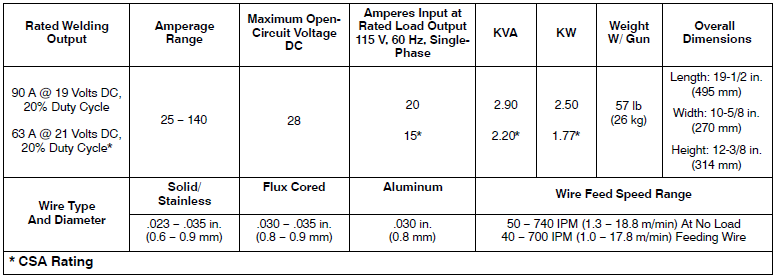
Specifications
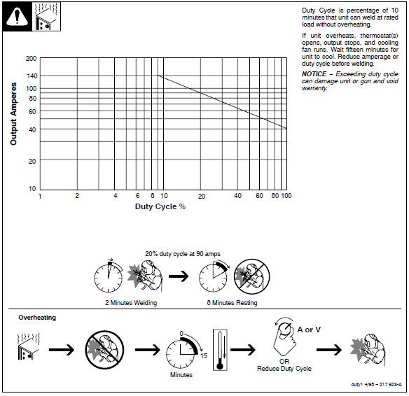
Duty Cycle And Overheating
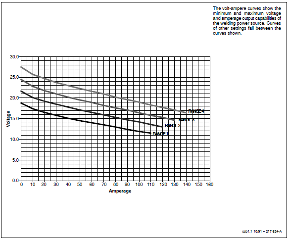
Volt-Ampere Curves
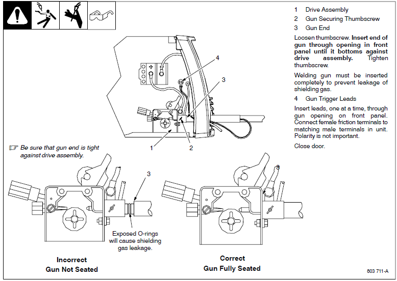
Installing a Welding Gun
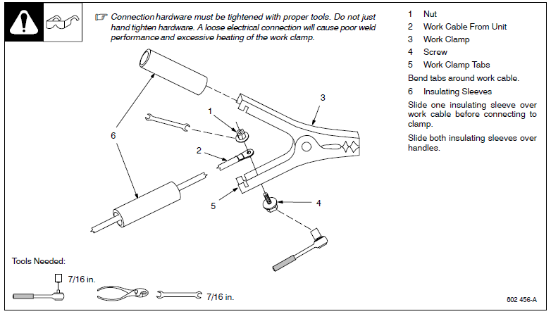
Installing Work Clamp
Process/Polarity Table

Changing Polarity
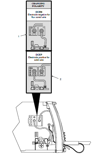
- Lead Connections For Direct Current Electrode Negative (DCEN)
- Lead Connections For Direct Current Electrode Positive (DCEP) Always read and follow the wire manufacturer’s recommended polarity, and see Section 5-3. Close the door.
Installing Gas Supply
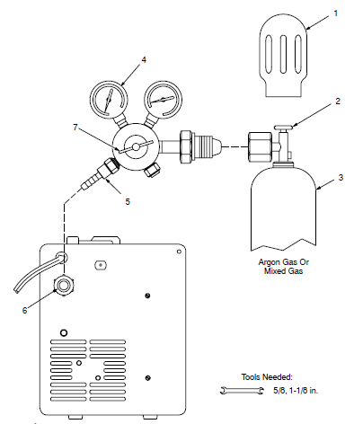
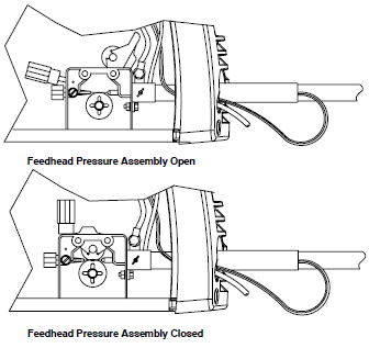
Obtain a gas cylinder and chain to run gear, wall, or other stationary support so the cylinder cannot fall and break off the valve.
- Cap
- Cylinder Valve: Remove the cap, stand to the side of the valve, and open the valve slightly. Gas flow blows dust and dirt from the valve. Close the valve.
- Cylinder
- Regulator/Flowmeter: Install the so face is vertical.
- Regulator/Flowmeter Gas
- Hose Connection
- Welding Power Source Gas
- Hose Connection: Connect the supplied gas hose between the regulator/flowmeter gas hose connection and fitting on the rear of the welding power source.
- Flow Adjust
The flow rate should be set when gas is flowing through the welding power source and welding gun. Open the feedhead pressure assembly so that the wire will not feed. Press the gun trigger to start the gas flow. The typical flow rate is 20 cph (cubic feet per hour). Check the wire manufacturer’s recommended flow rate. After the flow is set, close the feedhead pressure assembly.
Serial Number And Rating Label Location
- The serial number and rating information for this product are located on the back. Use the rating label to determine input power requirements and/or rated output. For future reference, write the serial number in the space provided on the back cover of this manual.
Selecting A Location And Connecting Input Power
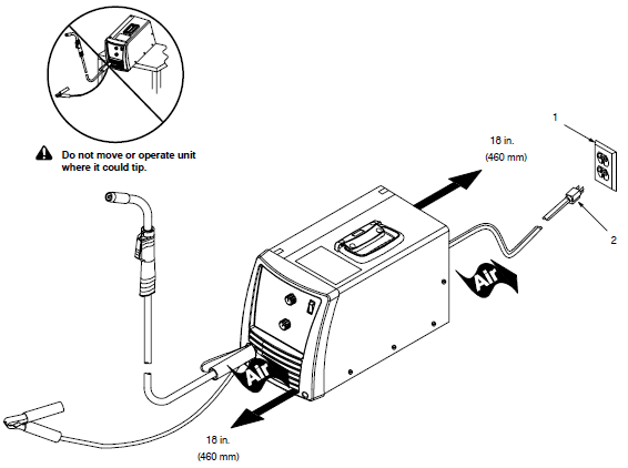
- Grounded Receptacle
A 115-volt, 20-ampere individual branch circuit protected by time-delay fuses or a circuit breaker is required. - Plug From Unit
Select an extension cord of 12 AWG for up to 50 ft (15 m) or 10 AWG for 50 up to 100 ft (30 m).
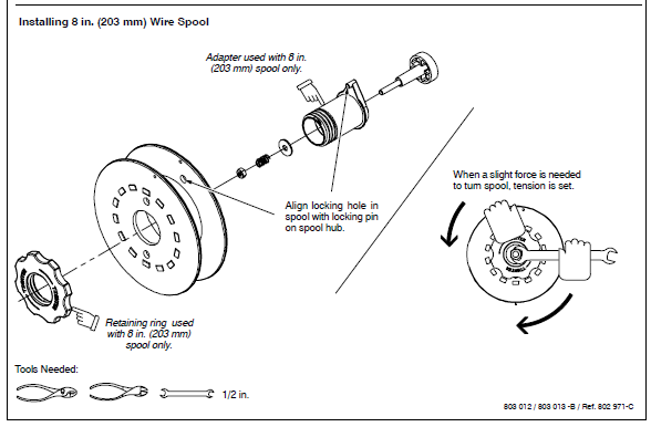
Installing Wire Spool And Adjusting Hub Tension
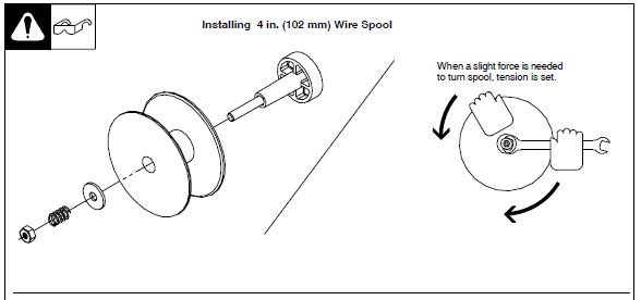
Installing Contact Tip And Nozzle
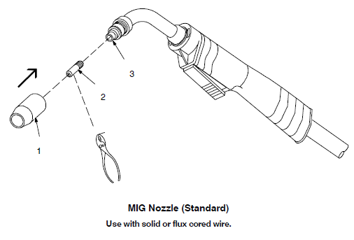
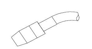 Push the nozzle over the contact tip and adapter until it is seated onto the adapter. The end of the contact tip will be flush with the end of the nozzle when installed properly.
Flux Nozzle (Optional)
Use with flux-cored wire only. Narrow design allows access in tight spaces and provides better visibility of the puddle during welding.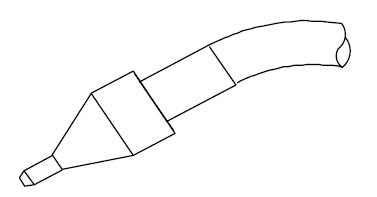 Push the nozzle over the contact tip and adapter until it is seated onto the adapter. The contact tip will be exposed approximately 7/16 in. (11.3 mm) when installed properly.
Tools Needed

Turn off the welding power source.
- Nozzle: Remove the nozzle.
- Contact Tip
- Tip Adapter: Thread welding wire through the gun (see Section 5-10). Slide the contact tip over the wire and tighten the tip into the tip adapter. Install the nozzle.
Threading Welding Wire
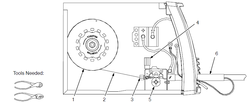
- Wire Spool
- Welding Wire
- Inlet Wire Guide
- Pressure Adjustment Knob
- Drive Roll
- Gun Conduit Cable Lay the gun cable out straight.
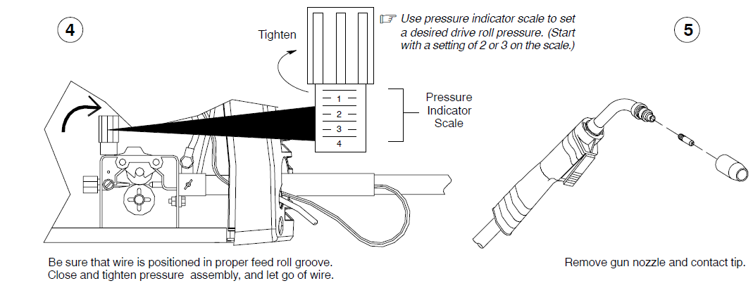
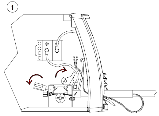 Open pressure assembly. Make sure the feed roll is set to the correct groove to match wire size (see Section 7-4).
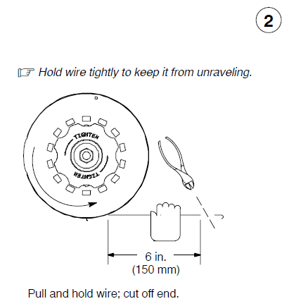
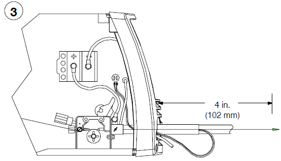 Straighten approximately 3 or 4 inches (76 or 102 mm) of wire before inserting a wire into the guides. Push the wire through the guides into the gun; continue to hold the wire.
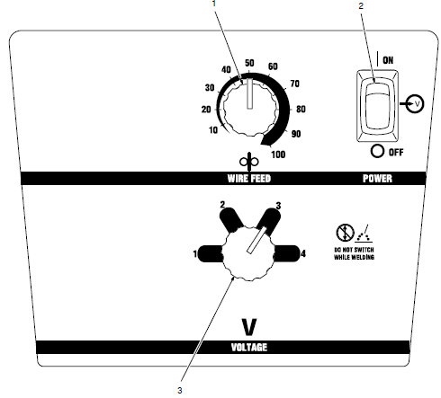
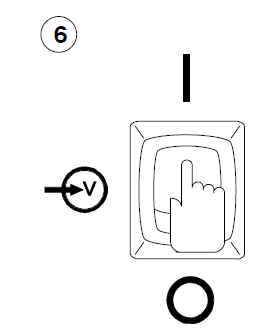 Turn the power on. Be sure that the Voltage range switch is set to range 1, 2, 3, or 4 to feed the wire. Rotate knob until it “clicks” into detent. The wire will not feed if the range switch is set between ranges.
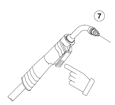 Press the gun trigger until the wire comes out of the gun. (Keep the gun cable as straight as possible.)
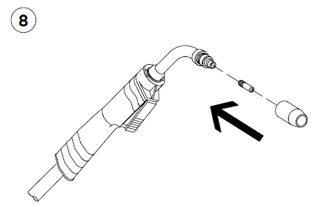 Be sure that the tip matches the wire diameter. Reinstall the contact tip and nozzle.
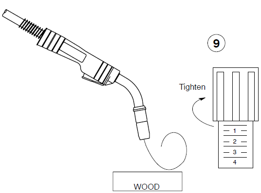 Feed wire to check the drive roll pressure. Tighten knob enough to prevent slipping. Cut off the wire. Close the door.
Controls
 Wire Speed Control: Use the control to select a wire feed speed. As the Voltage switch setting increases, the wire speed range also increases (see weld setting label in welding power source or Section 6-2).
- Power Switch
- Voltage Switch: The higher the selected number, the thicker the material that can be welded (see weld setting label in welding power source or Section 6-2). Do not switch under load.
MAINTENANCE & TROUBLESHOOTING
Routine Maintenance
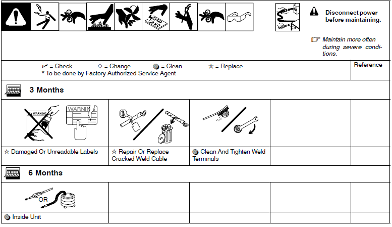
Overload Protection
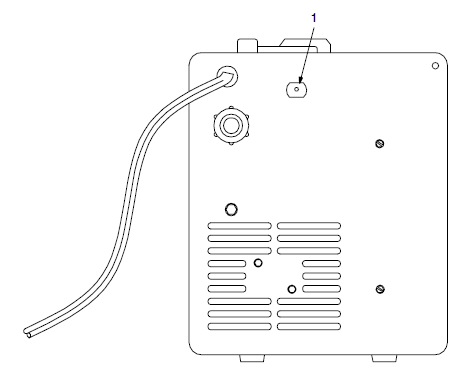
 Supplementary Protector CB1: CB1 protects the unit from overload. If CB1 opens, the unit shuts down. Reset the supplementary protector.
Drive Motor Protection
The drive motor protection circuit protects the drive motor from overload. If the drive motor becomes inoperative, release the gun trigger and wait until the protection circuit resets, allowing the drive motor to Feed wire again.
Changing Drive Roll Or Wire Inlet Guide
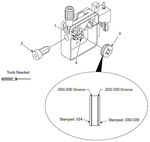
 Inlet Wire Guide Securing Screw
- Inlet Wire Guide: Loosen screw. Slide the tip as close to the drive rolls as possible without touching. Tighten screw.
- Drive Roll: The drive roll consists of two different-sized grooves. The stamped markings on the end surface of the drive roll refer to the groove on the opposite side of the drive roll. The groove closest to the motor shaft is the proper groove to thread (see Section 5-10).
- Retaining Pin: To secure the drive roll, locate the open slot and push the drive roll completely over the retaining pin, then rotate the drive roll (1/4 turn) to the closed slot.
Replacing Gun Contact Tip
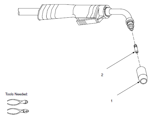
 Nozzle
- Contact Tip: Cut off the welding wire at the contact tip. Remove the nozzle. Remove the contact tip and install a new contact tip. Reinstall the nozzle.
Cleaning Or Replacing Gun Liner
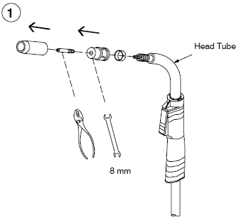 Remove nozzle, contact tip, adapter, gas diffuser, and wire outlet guide.
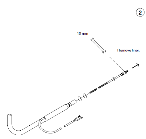
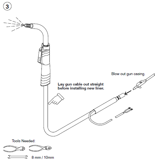
To Reassemble the Gun
Insert a new liner
Install the wire outlet guide so that 1/8 in (3 mm) of liner sticks out. Hand-tighten the outlet guide, and then tighten two full turns more. Cut the liner off so that 3/4 in. (19 mm) sticks out of the head tube. Install gas diffuser, adapter, contact tip, and nozzle.
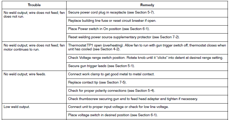
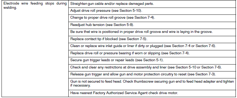
Troubleshooting Table
MIG WELDING (GMAW) GUIDELINES
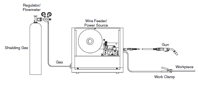
Typical MIG Process Connections
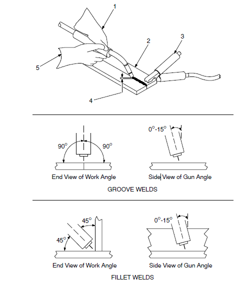
Holding And Positioning the Welding Gun
- Welding wire is energized when the gun trigger is pressed. Before lowering the helmet and pressing the trigger, be sure the wire is no more than 1/2 in. (13 mm) past the end of the nozzle, and the tip of the wire is positioned correctly on a seam.

- Hold the Gun and Control the Gun Trigger
- Workpiece
- Work Clamp
- Electrode Extension (Stickout) 1/4 to 1/2 in. (6 to 13 mm)
- Cradle Gun and Rest Hand on Workpiece
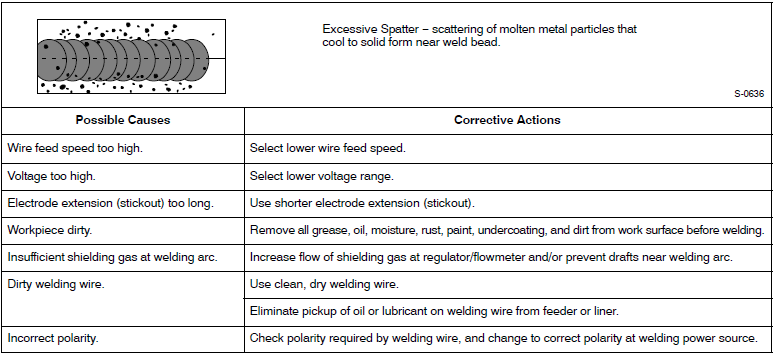
Troubleshooting − Excessive Spatter
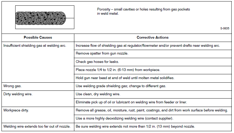
Troubleshooting − Porosity
Troubleshooting − Excessive Penetration

Accessories

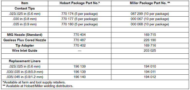
Consumables
Replacement Drive Rolls

Regulator/Flowmeter

For more manuals by Hobart Welders, visit ManualsLibraryy
Hobart Handler 140 Welder Machine- FAQs
How much power does the Hobart Handler 140 use?
The Handler 140 runs on 115V household power—just plug it into a standard outlet, no special wiring required.
What is the duty cycle of the Hobart Handler 140?
It has a 20% duty cycle at 90 amps, meaning it can weld for 2 minutes and rest for 8 minutes in a 10-minute cycle.
What is the maximum steel thickness the Hobart 140 can weld?
It can weld up to 1/4 inch thick mild steel, making it great for auto, home, or farm use.
How many amps does the Handler 140 draw?
It draws up to 140 amps and is compatible with a standard 115/120V, 20-amp circuit.
How do I calculate the power usage (watts) for this welder?
Use the formula: Volts × Amps = Watts. For example, 115V × 20A = 2,300W.
What size generator do I need for the Hobart 140?
You’ll need a generator rated between 4,500–5,500 watts to run the Handler 140 reliably.
What type of gas should I use with the Hobart 140?
Use a mix of Argon and CO₂ (C25) gas when MIG welding. Check the machine’s chart for correct settings based on wire size and material thickness.
How is the welder’s duty cycle calculated?
Duty Cycle = (Weld Time ÷ Total Cycle Time) × 100. For example, if it welds for 2 minutes out of 10, the duty cycle is 20%.

 Wire Speed Control: Use the control to select a wire feed speed. As the Voltage switch setting increases, the wire speed range also increases (see weld setting label in welding power source or Section 6-2).
 Supplementary Protector CB1: CB1 protects the unit from overload. If CB1 opens, the unit shuts down. Reset the supplementary protector.
 Inlet Wire Guide Securing Screw
 Nozzle