Honeywell ECC 50 100 Emergency Voice Evacuation System

Installation Precautions
Adherence to the following will aid in problem-free installation with long-term reliability:
WARNING – Several different sources of power can be connected to the fire alarm control panel. Disconnect all sources of power before servicing. Control unit and associated equipment may be damaged by removing and/or inserting cards, modules, or interconnecting cables while the unit is energized. Do not attempt to install, service, or operate this unit until the manuals are read and understood.
CAUTION – System Re-acceptance Test after Software Changes: To ensure proper system operation, this product must be tested in accordance with NFPA 72 after any programming operation or change in site-specific software. Reacceptance testing is required after any change, addition or deletion of system components, or after any modification, repair or adjustment to system hardware or wiring. All components, circuits, system operations, or software functions known to be affected by a change must be 100% tested. In addition, to ensure that other operations are not inadvertently affected, at least 10% of the initiating devices that are not directly affected by the change, up to a maximum of 50 devices, must also be tested and proper system operation verified.
This system meets NFPA requirements for operation at 0-49º C/32-120º F and at a relative humidity 93% ± 2% RH (noncondensing) at 32°C ± 2°C (90°F ± 3°F). However, the useful life of the system’s standby batteries and the electronic components may be adversely affected by extreme temperature ranges and humidity. Therefore, it is recommended that this system and its peripherals be installed in an environment with a normal room temperature of 15-27º C/60-80º F. Verify that wire sizes are adequate for all initiating and indicating device loops. Most devices cannot tolerate more than a 10% I.R. drop from the specified device voltage.
Product Description
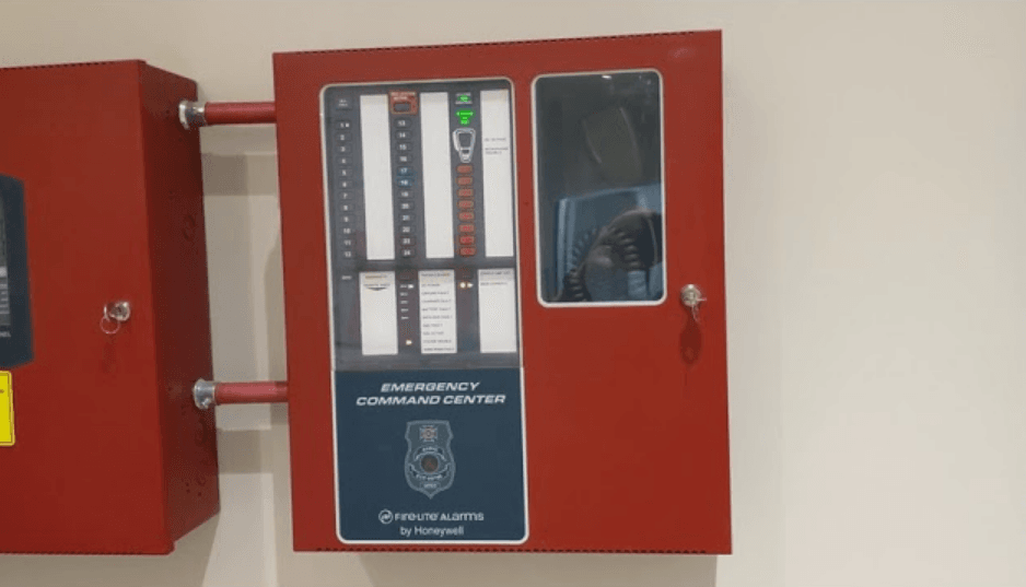
The Fire Lite Emergency Command Center ECC-50/100 is a single-channel, 50-watt, 25 VRMS emergency voice evacuation panel that may be used for fire applications, mass notification applications, or both. The ECC-50/100 comes standard with one speaker circuit. The panel provides the ability to record fourteen field programmable messages (up to 60 seconds each) with an integral microphone or from an external audio source. An integral power supply with a battery charger supplies operational power. A 50-watt audio amplifier is built into each panel. An optional second 50-watt amplifier (ECC-50W-25/70V) is also available for backup purposes or to provide an additional 50 watts. The backup amplifier is available in either 25 volts or 70 volts, depending on which application is necessary. Automatic activation of the ECC-50/100 by an FACP is possible via eight Command Input Circuits (CMD) or via the ACS/ANN Bus serial communications link from the MS-600 (UD)LS and MS-9200UDLS FACPs. Two Command Input Circuits can be independently field programmed for activation by an FACP Notification Appliance Circuit, reverse polarity or by closure of a supervised normally open contact, and six Command Input Circuits activate on contact closure. CMD 1 and CMD 2 provide terminals for NAC input and output to allow installation of the audio panel anywhere along the NAC circuit being used to activate it. If the message generator fails, the system automatically reverts to a backup tone generator. Power is fed independently to each amplifier so that a short circuit in one amplifier will not shut down the other. Full output power of 50 watts per amplifier is generated while in a low battery condition. Power is not diminished when the optional 70 VRMS transformer module is installed. Audio is amplified utilizing modern integrated circuits as opposed to transformer technology. This provides for very low signal distortion for crystal clear audio. Primary applications for the audio panels include protecting structures such as military facilities, restaurants, schools, auditoriums, places of worship, buildings with occupancies over 50, etc. The ECC-50/100 is designed to interface directly to addressable or conventional (CMD inputs 1-8) fire alarm control panels or can be used with the ECC-50/125DA panel to distribute audio in systems that require more than 100 watts.
Product Features
- Modular design for maximum system flexibility and easy expansion
- Removable terminal blocks for ease of servicing and module replacement
- 50 watts of 25 VRMS audio power (expandable to 100 watts)
- 2 amp Notification Appliance Circuit (NAC) output, sync generator, or follower for protocols:
- System Sensor
- Wheelock
- Gentex
- Optional 70.7 VRMS conversion transformer available for the primary amplifier (note that speaker wiring continues to be supervised in standby, alarm and when background music is playing with this optional transformer installed)
- Eight Command Input Circuits to activate messages 1 to 8:
- CMD1 and CMD2 are field selectable to be activated from 12 or 24 VDC Notification Appliance Circuits (reverse polarity) or contact closures
- CMD3-CMD8 are activated by contact closures
- Speaker Circuits
- Single Style Y (Class B) or Style Z (Class A) speaker circuit
- two Style Y (Class B) or Style Z (Class A) speaker circuits (with optional ECC-50W-25/70V Audio Amplifier installed)
- eight Style Y (Class B) or Style Z (Class A) speaker circuits (with optional ECC-50W-25/70V and ECC-CE6 installed)
- ECC-50/100 can be controlled by an FACP via the ANN/ACS (EIA-485) link. Compatible FACPs include the MS-9600(UD)LS and MS-9200UDLS.
- Integral supervised microphone
- Microphone time-out feature which reverts back to prerecorded message if emergency page exceeds the programmed time
- Up to 14 recorded messages
- 14 prerecorded messages for fire, emergency, and weather alerts
- Field-selectable message and custom message recording capability using the local microphone, a USB port, or an external audio input
- External Audio Input can be used for background music
- Up to 60-second message duration for all messages
- Integral tone generators are field selectable for multiple tone types
- Powered by an integral AC power supply or batteries during AC fail
- Programmable delay of immediate, 2 hours, or 6 hours reporting of AC Loss
- Piezo sounder for local trouble
- 100 event history log
- Three Form-C relays:
- AC Power Loss Relay – TB1
- System Trouble Relay – TB2
- MNS Active – TB3
- 500 mA (0.5A) Special Application (auxiliary power) output for addressable modules when interfaced with compatible addressable FACPs and End-of-Line power supervision relays
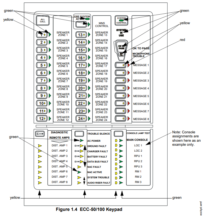
- System Status LEDs (refer to “Controls and Indicators” on page 20)
- Integral Dress Panel
- Optional TR-CE semi-flush trim ring
- Any combination of up to eight (8) of:
- Optional ECC-RM Remote Microphone (includes cabinet).
- Optional ECC-RPU Remote Page Unit (includes cabinet)
- Optional ECC-LOC (includes cabinet)
- Optional ECC-CE6 Circuit Expander
- Optional ECC-50W-25V amplifier, 50 watts, 25 volts
- Optional ECC-50W-70V amplifier, 50 watts, 70 volts
- Optional ECC-50DA distributed amplifier, 50 watts
- Optional ECC-125DA distributed amplifier, 125 watts
- Optional ECC-50BDA distributed amplifier, 50/100 watts
Input/Output Circuit Specifications
ECC-50/100 Main Control Board
AC Power – TB15
- ECC-50/100: 120 VAC, 60 Hz, 3.5 amps (HOT, NEU)
- ECC-50/100E: 240 VAC, 50 Hz, 2.0 amps (HOT=HotLeg1, NEU=HotLeg2)
- Wire size: minimum #14 AWG (2.00 mm2) with 600 V insulation.
Battery (lead acid only) – J7
- Maximum Charging Circuit: Normal Flat Charge – 27.3V @ 2.8 amps
- Maximum Charger Capacity: 26 amp-hour battery. (ECC cabinet holds max. 18-Amp-Hour Battery.
- Minimum Battery Size: 12 Amp-Hour
MNS Active Relay – TB1
- Form-C relay contact rating: 2.0 amps @ 30 VDC (resistive), 0.5 amps @ 30 VAC (resistive),
Form-C Trouble Relay – TB2
- Form-C relay contact rating: 2.0 amps @ 30 VDC (resistive), 0.5 amp @ 30 VAC (resistive).
AC Loss Relay – TB3
- Form-C relay contact rating: 2.0 amps @ 30 VDC (resistive), 0.5 amps @ 30 VAC (resistive),
NAC Output – TB19, Terminals 1 (B+), 2 (A+), 3 (A-), & 4 (B-)
- One (1) Style Y (Class B) or Style Z (Class A) circuit
- Power-limited circuitry (Class 2), supervised
- Nominal operating voltage: 24 VDC
- Maximum signaling current for special application power: 2.0 amps
- Maximum signaling current for regulated power: 200mA
- Current limit: fuseless, electronic, power-limited
- Maximum wiring impedance: 1 Ω
- End-Of-Line Resistor: 4.7 KΩ, ½ watt, (P/N 71252) required for Style Y (Class B) operation
- Refer to the Device Compatibility Document for the listed compatible devices.
NAC Follower – TB18, Terminals 3 (IN+), 4 (IN-), 1 (OUT+) & 2 (OUT-)
- Connections for FACP NAC synchronization trigger signal
- Output terminals: pass-through to other system components
- Trigger input voltage: 9 to 32 VDC, 24 VDC rated
- Input current draw in Alarm condition: 10 mA at rated voltage
Special Application Power (Aux. Power) – TB17 Terminals 1(+) & 2(-)
- Up to 500 mA @ 24 VDC of special application power is available for powering addressable modules and associated End-of-Line power supervision relays.
- Power-limited (Class 2) circuitry. Refer to the Device Compatibility Document for a list of compatible devices.
Speaker Volume Control Override – TB23, Terminals 1 (B+), 2 (A+), 3 (A-), & 4 (B-)
- Style Y (Class B) or Style Z (Class A) circuit
- Special Application power
- Power-limited (Class 2) circuitry, supervised
- Nominal operating voltage: 24 VDC
- Maximum signaling current: 0.25 amps
- Current limit: fuseless, electronic, power-limited
- End-Of-Line Resistor: 4.7 KΩ, ½ watt, (P/N 71252) required for Style Y (Class B) operation
Controls and Indicators

Push-Button Controls
- All Call
- MNS Control
- System Control
- Speaker Select 1-24
- Message Select 1-8
- Diagnostic Select
- Trouble Silence
- Console Lamp Test
LED Indicators (visible with door closed)
- Fire System Active (green)
- MNS Control (green)
- System Control (green)
- System in Use (green)
- Speaker Zone 1-24 Active (green)
- Speaker Zone 1-24 Fault (yellow)
- OK to Page (green)
- Microphone Trouble (yellow)
- Message 1-8 Active (red)
- Message 1-8 Fault (yellow)
- Remote Amplifier 1-8 Fault (yellow)
- LOC/RPU/RM 1-8 Fault (yellow)
- LOC/RPU/RM 1-8 Active (green)
- Main Console Fault (yellow)
- AC Power (green)
- Ground Fault (yellow)
- Charger Fault (yellow)
- Battery Fault (yellow)
- Data Bus Fault (yellow)
- NAC Fault (yellow)
- NAC Active (green)
- System Trouble (yellow)
- Audio Riser Fault (yellow)
Installation
Mounting Options
The cabinet may be semi-flush or surface-mounted. The cabinet mounts using three key slots at the top of the backbox and two additional 0.250″ diameter holes located at the bottom. Carefully unpack the system and check for shipping damage. Mount the cabinet in a clean, dry, vibration-free area where extreme temperatures are not encountered. The area should be readily accessible with sufficient room to easily install and maintain the panel. Locate the top of the cabinet approximately five feet above the floor, with the hinge mounting on the left. Determine the number of conductors required for the devices to be installed. Sufficient knockouts are provided for wiring convenience. Select the appropriate knockout(s) and pull the required conductors into the box. Note that knockouts are also located on the back of the cabinet. All wiring should be in accordance with the National and/or Local codes for fire alarm systems. Refer to Figure 2.4 for knockouts that cannot
be used.
Backbox Installation
Removing the Dress Panel
- Open the door and lift the door off the pin hinges.
- Loosen the two (2) screws that secure the dress panel to the backbox. Then, lift up to swing the dress panel open.
- Disconnect the ground wire from the dress panel.
- Unplug the cable on the display board at J2. This is the connection to the main control board on the chassis.
- Lift the dress panel up and gently pull the lower hinge out of the backbox. Gently pull down to remove the top hinge. Store the dress panel in a safe place.

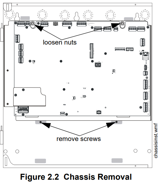
Removing the Chassis Assembly
- If present, remove the two (2) screws which fasten the lower chassis tabs to the backbox. These are for shipping purposes only and do not need to be reinstalled.
- Loosen the two nuts that secure the top of the chassis with an 11/32” socket.
- Carefully lift up and remove the chassis assembly from the backbox and store it in a safe, clean place. Avoid static discharge, which may damage static-sensitive components on the board.

Mounting the Backbox
- Mark and predrill hole in the wall for the center top keyhole mounting bolt using the dimensions illustrated in Figure 2.4 on page 29.
- Install center top fastener in the wall with the screw head protruding.
- Place backbox over the top screw, level and secure.
- Mark and drill the left and right upper and lower mounting holes.
Note: Outer holes (closest to sidewall) are used for 16” O.C. stud mounting. - Install the remaining fasteners and tighten.
- Carefully reinstall the chassis assembly and dress panel by reversing the steps above. Use appropriate precautions to prevent damage to components due to static discharge. When reinstalling the chassis assembly, be sure that all four (4) tabs are seated properly in the slots of the backbox to avoid possible damage to the unit.

- Draw wires through the respective knockout locations. An optional Trim Ring (P/N TR-CE) is available for semi-flush mount installations.
Programming

All ECC programming is done using the built-in web-based programming utility. It is recommended that tone selection, message repeat cycles, and background music options be reviewed and approved by the local AHJ. To start programming, use a standard CAT5e Ethernet cable to connect a personal computer’s IP port (Ethernet) to the IP port (Ethernet) J2 on the main control board (right side of the board). See the computer’s local area network connection address as follows:
- IP address: 169.254.3.5
- Subnet mask: 255.255.0.0
Activate the PC’s web browser (Microsoft Internet Explorer version 8 or Mozilla Firefox). Enter the following in the browser’s navigation bar: http://169.254.3.3
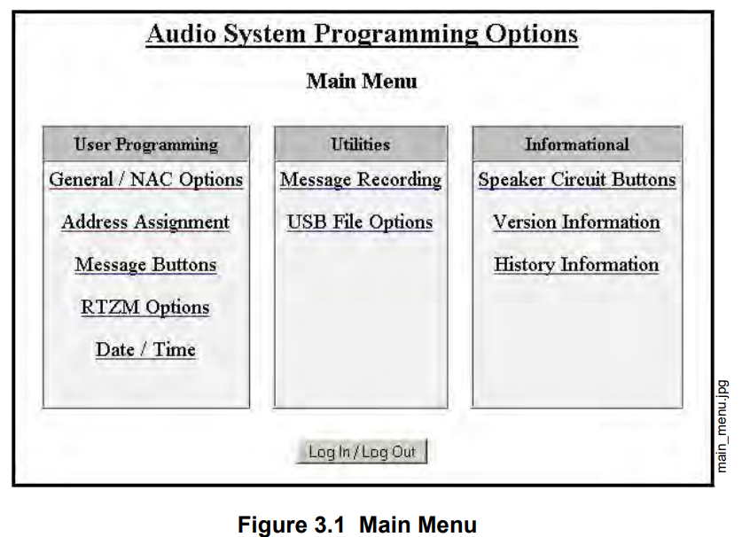
The main menu will display and allow further menu navigation.
Security and Data Protection:
NO ENCRYPTION EMPLOYED
- Communication Security:
- a. Level 1
- Stored Data Security:
- a. Level 0
- Access Control Security:
- a. Level 1
- Physical Security:
- a. Level 1
- Audit Control: not provided
ECC-50/100 Panel Installation/Maintenance Security Checklist
System Description:_____________________________________________________
System Location: _______________________________________________________
Installer: _______________________________________ Date: __________________
Complete the following security tasks for each ECC-50/100 installation.
- Install the ECC-50/100 panel in a secure location, considering both software and hardware vulnerabilities.
- Change the default password to a unique password.
- Securely configure networks and firewalls.
- Assess security risks.
- Develop a Disaster and Recovery Plan.
- Develop a Backup and Recovery Strategy.
- Install, configure, and maintain anti-virus software on all computers that access the panel.
- Keep the operating system updated and maintain version compatibility with the panel.
- Deliver all required system information upon delivery to the system owner.
- Train end-users on security maintenance tasks upon system delivery.
- For decommissioning, dispose of data securely.
- Ensure the Ethernet cable is removed from the ECC-50/100 when not being utilized for configuration.
Main Menu – User Programming
This screen shows the main menu for the ECC user programming options. Changes to programming require a valid password for system login. Note that a password is NOT required to change the date/time, view the informational screens, or view the panel history.
Password Options
Changes to ECC programming require a valid password login. Programming changes cannot be made when there is an active event in the system.
- Log In Password: The default password for the ECC-50/100 is 0000.
- New Password: It is recommended that the password be changed to increase system security.
- Valid passwords: contain four digits from 0000-9999.
- Verify New Password: Re-enter the new password for confirmation.
- Inactivity Timeout: Select the amount of time, 5 minutes, 10 minutes, 20 minutes, 30 minutes, or 60 minutes, the system is allowed to remain idle before automatic user log out. The timeout feature helps the system protect against unauthorized programming changes.
- Log Out: When all programming has been completed, the user must log out to allow the system to reboot and apply the programming changes.
General/NAC Options
General Options
- Unit Operation Select whether the ECC will function for Fire Evacuation, Mass Notification, or a Combination of both.
- Event Priority When Combo or Mass Notification is selected for Unit Operation, select whether Mass Notification events or Fire Evacuation events will take priority in the system. If Mass Notification is selected as the Unit Operation with the Event Priority set to Fire Evacuation, the ECC will be a mass notification only system but will allow the FACP to override it if a fire alarm sounds. If Mass Notification is selected as the Unit Operation with the Event Priority also set to Mass Notification, the ECC will not have any fire evacuation capabilities and will report mass notification events to the FACP. In this configuration, FACP outputs can be turned off for mass notification events if desired.
- FACP Data Bus Control. If an FACP will directly communicate with the ECC, select which communication protocol will be used, ACS-Bus or ANN-Bus.
- FACP Data Bus Address. This field has no effect on programming and is used for informational purposes only. When using the FACP ACS-bus protocol, address 01 must be enabled in the FACP programming. When using the ANN-Bus protocol, the FACP will automatically detect the audio system connection during annunciator auto-configuration. No ANN-Bus address selection is necessary at the FACP. Enter the ECC’s address (1-8) here. If FACP control of the ECC is not selected, enter 0.
- 24-Hour Resound As enabled (default), the 24-Hour Resound feature causes the piezo on the ECC to sound a reminder ‘beep’ for alarms and troubles after the panel has been silenced.
- Canadian Configuration: Selecting enable will configure the panel to comply with Canadian requirements. See Appendix C for more information.
- Class A / Style Z Select enable if all circuits on the ECC will operate in Class A (Style Z) or disabled if all circuits will operate in Class B (Style Y).
- Canadian Isolator Modules. If audio isolator modules are required in the system, select enabled. Refer to “Audio Room Isolator Modules” on page 103 for more information.
- AC Loss Delay. The reporting of a loss of AC power using the AC Loss relay output can be delayed by programming the length of the desired delay. The factory default setting is 2 hours.
- Options are 0, 2, 6, 12, or 23 hours.
- Secondary Amplifier If an ECC-50W-25/70V is installed, select whether it will be used as a backup amplifier or for secondary speaker circuits. If an ECC-50W-25/70V is not installed, select none.
- Primary Amp 70 VAC. This field does not affect programming and is used for informational purposes only. The system can be converted from 25V to 70V by installing the ECC-XRM-70V. If this transformer has been installed, be sure that SW5 on the main control board has been set to “70V” operation. Use this field to record the amplifier’s settings.
- Secondary Amp 70 VAC. This field does not affect programming and is used for informational purposes only. When the ECC-XRM-70V has been installed and a secondary amplifier is required, the model number ECC-50W-70V must be used. Use this field to record which model has been installed in the system.
- External Audio Input If there is a permanent connection to TB5 on the display board, select whether the external audio input will function as Background Music or External Paging – Night Ring. See Section 4.4.15 for more information.
- IP Address The default IP address of 169.254.3.3 can be changed to another address with numbers from 0-255. Changing the IP address is suggested for a higher level of security on the system’s programming. This number should be written down and stored in a safe location.
- Identification: Enter a label for this ECC system. Up to 80 characters may be entered.
Operating Instructions
Main Control Panel Keypad Labels
The ECC-50/100 is shipped with slide-in labels installed in the keypad as illustrated in the following figure. Blank labels are provided to allow the user to customize the zone and message description. Remove the center piece to access the label slots. Using a small, flat screwdriver, press and release the small plastic latch located on the left side of the center piece. The top row of labels can be easily removed by sliding them down through the slots in the middle of the keypad and installed by sliding them up. The bottom row of labels can be removed by sliding them up through the slots in the middle of they keypad and installed by sliding them down into position.
For more manuals by Honeywell, visit ManualsLibraryy
Honeywell ECC 50 100 Emergency Voice Evacuation System-FAQs
What is an emergency voice evacuation system?
It’s a system designed to help building management coordinate evacuations by broadcasting clear voice messages during emergencies, ensuring occupant safety.
What does ECC stand for in an emergency context?
ECC can refer to Emergency Coordination Center, which is a secure location used to coordinate response and recovery during large-scale emergencies.
What are emergency control function interfaces?
These interfaces allow fire alarm systems and other building systems to communicate with each other during a fire or emergency for better coordination and response.
What are the three main types of evacuation?
The three evacuation strategies include:
1. Simultaneous evacuation
2. Vertical or horizontal phased evacuation
3. Silent alarm evacuation
When is a voice evacuation system required?
A voice fire alarm system is required in buildings with over 1,000 occupants, especially in assembly areas where manual fire alarm systems are already mandatory above 300 people.
What does ECC mean in CPR training?
In CPR, ECC stands for Emergency Cardiovascular Care, which includes life-saving training and guidelines for cardiac arrest and other first aid emergencies.
What’s the difference between ECC and EOC?
The Emergency Coordination Center (ECC) and Emergency Operations Center (EOC) are both used during emergencies. While often interchangeable, some regulations (e.g., in airports) may define them separately.
Who is the emergency controller in a building?
An Emergency Control Organisation (ECO) is a trained team responsible for managing emergency responses—like evacuations, first aid, and contacting emergency services.


