Honeywell VISTA-20PCN Programming Alarm System
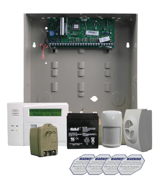
TO ENTER PROGRAMMING MODE:
Local programming requires the use of an alpha keypad connected to the keypad terminals on the control.
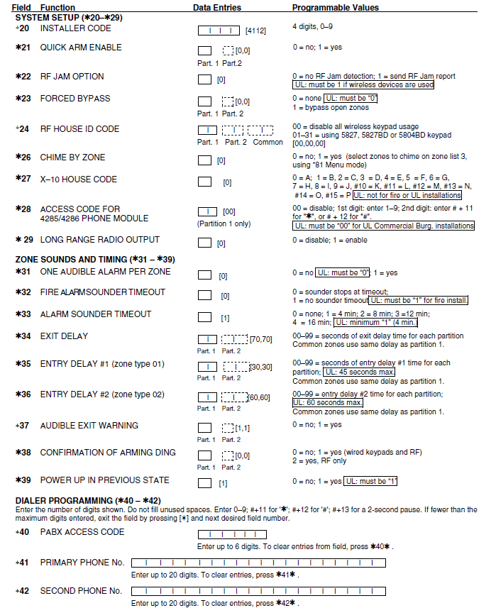
- POWER UP, then depress [✱] and [#] both at once, within 50 seconds of powering up.
- Initially, key: Installer Code (4 + 1 + 1 + 2) plus 8 + 0 + 0.
- If a different Installer Code is programmed, key: New Installer Code + 8 + 0 + 0. (If ✱98 was used to exit previously, method 1 above must be used to enter the program mode again)
Data Field Programming Procedures
| Task | Procedure |
| Go to a Data Field | Press [*] + [Field Number], followed by the required entry. |
| Entering Data | When the desired field number appears, simply make the required entry. When the last entry for a field is entered, the keypad beeps three times and automatically displays the next data field in sequence. If the number of digits that you need to enter in a data field is less than the maximum digits available (for example, the phone number fields *41, *42), enter the desired data, then press [*]. The entry is terminated and the next data field number appears. |
| Review a Data Field | Press [#] + [Field Number]. Data will be displayed for that field number. No changes will be accepted in this mode. |
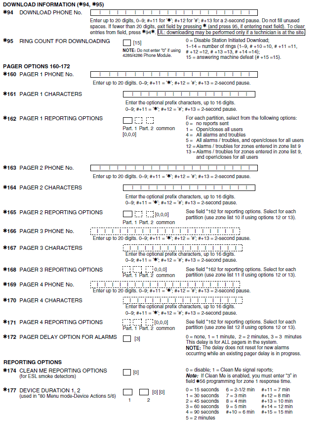
| Deleting an Entry | Press [*] + [Field Number] + [*]. (Applies only to fields *40–*43, *45, *94, and pager programming fields) |
Interactive Mode Programming (∗56, *57, ∗58, ∗80, ∗81, ∗82)
- Press [✱] + [Interactive Mode No.] (for example, ✱56). The alpha display keypad will display the first of a series of prompts requesting entries.
Interactive Mode Used to Program ✱56 Zone Programming Zone characteristics, report codes, alpha descriptors, and serial numbers for 5800 RF transmitters. ✱57 Function Key Programming Unlabeled keypad keys (known as ABCD keys) for special functions ✱58 Zone Programming (Expert mode) Same options as *56 mode, but with fewer prompts. Intended for those familiar with this type of programming, otherwise *56 mode is recommended. ✱79 Output Device Mapping Assign module addresses and map individual relays/powerline carrier devices ✱80 Output Programming 4229 or 4204 Relay modules, Powerline Carrier devices, or on-board triggers ✱81 Zone List Programming Zone Lists for relay/powerline carrier activation, chime zones, pager zones, etc. ✱82 Alpha Programming Zone alpha descriptors
INITIALIZE DOWNLOAD and RESET DEFAULTS
- ✱96 Initializes download ID and subscriber account number.
- ✱97 Sets all data fields to the original factory default values.
TO EXIT PROGRAMMING MODE:
- ✱98 Exits programming mode and prevents re-entry by: Installer Code + 8 + 0 + 0. If ✱98 is used to exit programming mode, the system must be powered down, and method 1 above must be used to enter the programming mode.
- ✱99 Exits programming mode and allows re-entry by: Installer Code + 8 + 0 + 0 or method 1 above.
- Special Messages
- OC = OPEN CIRCUIT (no communication between Keypad and Control).
- EE or ENTRY ERROR = ERROR (invalid field number entered; re-enter valid field number).
- After powering up, AC, dI (disabled), or Busy Standby and NOT READY will be displayed after approximately 4 seconds. This will revert to a “Ready” message in approximately 1 minute, which allows PIRS, etc., to stabilize. You can bypass this delay by pressing [#] + [0].
- If E4 or E8 appears, more zones than the expansion units can handle have been programmed. Correct the programming and then completely de-power and re-power the control to clear this indication and remove the disabled indication
PROGRAMMING FORM
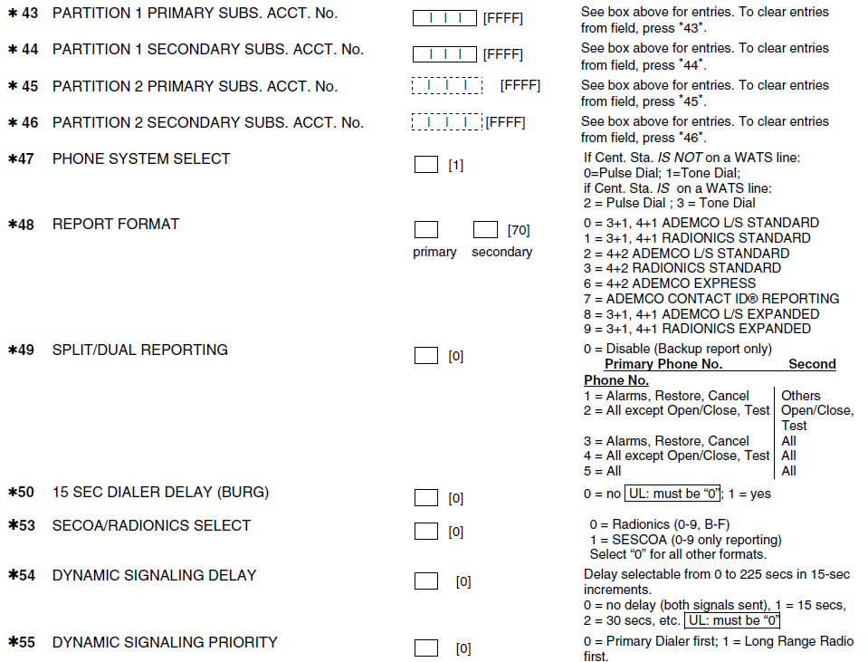
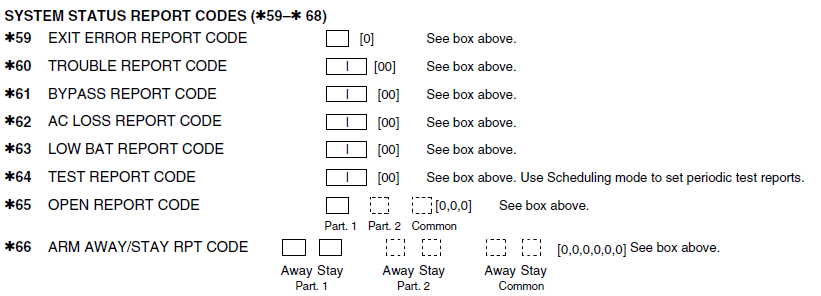
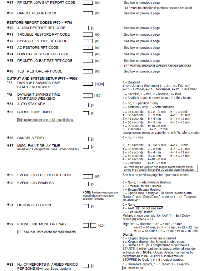
- Entry of a number other than one specified will give unpredictable results. Values shown in brackets are factory defaults. Entries shown in dashed boxes indicate partition entries for VISTA-20P only (not applicable for VISTA-15P)


- TO PROGRAM SYSTEM STATUS, & RESTORE REPORT CODES (✱59 – ✱76, & ✱89):
- For 3+1 or 4+1 Standard Format: Enter a code in the first box: 1–9, #+10 for 0, #+11 for B, #+12 for C, #+13 for D, #+14 for E, #+15 for F.
- A 0 (not #+10) in the first box will disable a report. A 0 (not #+10) in the second box will result in automatic advance to the next field.
- For Expanded or 4+2 Format: Enter codes in both boxes (1st and 2nd digits) for 1–9, 0, or B–F, as described above.
- A 0 (not #+10) in the second box will eliminate the expanded message for that report. A 0 (not #+10) in both boxes will disable the report.
- For Ademco Contact ID® Reporting: Enter any digit (other than 0) in the first box, to enable zone to report (entries in the second boxes are ignored


Configurable Zone Types Worksheets
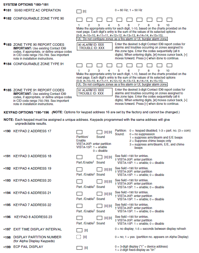
- Configurable zone types 90 and 91 can be programmed via the downloader software or from a keypad using data fields* 182-* 185. Configurable zone types 92 and 93 (VISTA-20P only) can only be programmed using the downloader software.
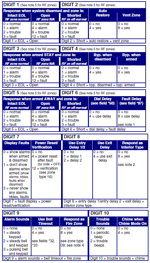
- Programming Configurable Zone Type options involves entering 10 digits in the data field *182 for zone type 90 and field *184 for zone type 91, where each digit represents the sum of the values of its various options as shown in the tables below. Use fields *183 and *185 to program Contact ID report codes for these zone types.

NOTES:
- Do not use the “fault delay” option with a configurable zone type if it is set for an entry or exit delay, otherwise, unpredictable results may occur.
- To create an interior type zone, select “respond as interior zone type” (Digit 8, interior type = yes), and set zone response to “fault” in digits 3-4 to ensure fault displays; do not set as “normal,” “alarm,” or “trouble.”
- Do not set fire zones to respond as a “fault” (digits 1-6), otherwise, faults will not display unless the [∗] key is pressed.
- 4219/4229 modules must use EOLR,s or unpredictable results may occur.
- RF Zones: The “open” option in digits 1, 3, and 5 is not applicable for RF zones. Use the “intact EOL” option for normal RF zone conditions and “shorted” for off-normal RF zone conditions.
- Zone-Doubling/Double-Balanced: A short on either zone of a zone-doubled pair or on a double-balanced zone causes a tamper condition.
57 FUNCTION KEY PROGRAMMING
| Option | Function | A | B | C | D | Comments |
| 01 | Paging | |||||
| 02 | Time Display | |||||
| 03 | Arm AWAY | |||||
| 04 | Arm STAY | |||||
| 05 | Arm NIGHT-STAY | |||||
| 06 | Step Arming | |||||
| 07 | Device Activation | Device: | ||||
| 08 | Comm. Test | |||||
| 09 | Macro Key 1 | |||||
| 10 | Macro Key 2 |
| 00 | Emergency Keys: | |||||
| Personal Emergency | ||||||
| Silent Alarm | ||||||
| Audible Alarm | ||||||
| Fire | ||||||
| Emergency Keys: A = [1] / [*] B = [*] / [#] C = [3] / [#] | ||||||
✱81 ZONE LISTS FOR OUTPUT DEVICES
- Fill in the required data on the worksheet below, and follow the procedure in the installation manual as you enter the data during the displays and prompts that appear in sequence.
- Note: Record desired zone numbers below, noting that a list may include any or all of the system’s zone numbers
List No. Used For… Contains These Zones… 01 General Purpose (GP) 02 General Purpose 03 Chime-by-Zone or GP 04 Cross Zones 05 Night-Stay Zones or GP 06 General Purpose 07 General Purpose 08 General Purpose 09 Zones activating pager 1 10 Zones activating pager 2 11 12
Zones activating pager 3 Zones activating pager 4
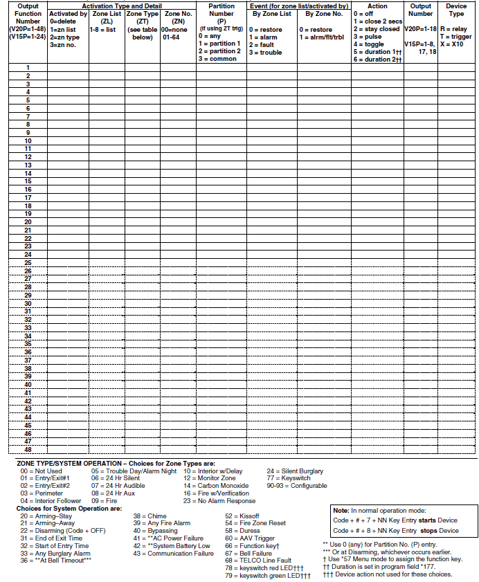
✱80 OUTPUT DEFINITIONS
- Fill in the required data on the worksheet below and follow the programming procedure in the installation manual as you enter the data during the displays and prompts that appear in sequence.
Notes: - 1. For Relays, 4229 and 4204 devices are programmed in *79, *80, and *81 modes.
- 2. For Powerline Carrier devices (PLCD), field ✱27 must be programmed with a House Code.
- 3. Tampers of expansion units cannot be used to operate devices

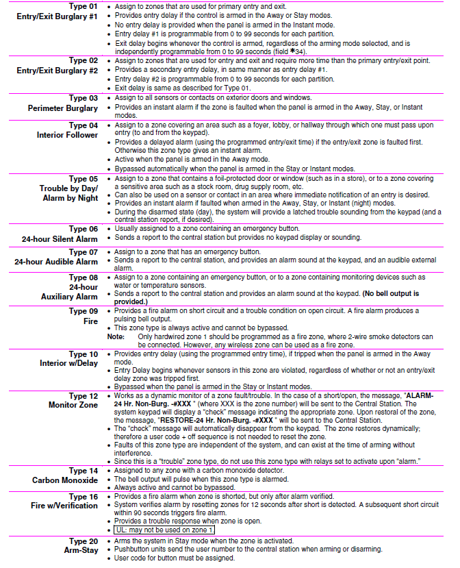
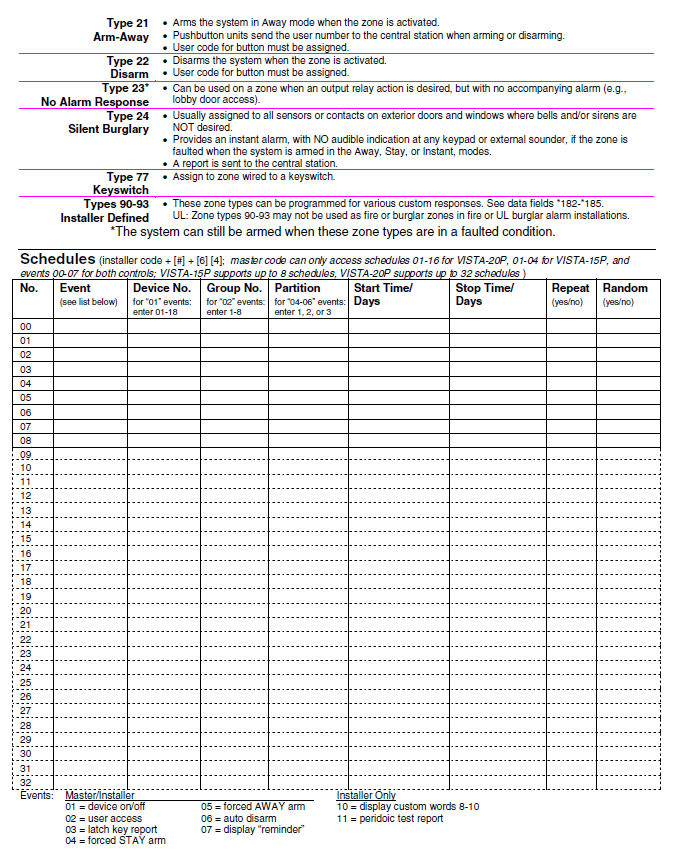
Zone Type Definitions
- Type 00 Use this zone type if the zone is not used.
- Zone Not Used


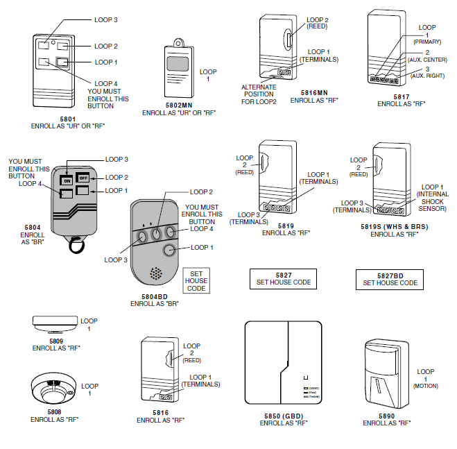
5800 Series Transmitter Input Loop Identification
- All of the transmitters illustrated below have one or more unique factory-assigned input (loop) ID codes. Each of the inputs requires its own programming zone (e.g., a 5804’s four inputs require four programming zones).
- Transmitter inputs entered as:
- “RF” (Supervised RF) Type sends periodic check-in signals, as well as fault, restore, and low battery signals. The transmitter must remain within the receiver’s range.
- “UR” (Unsupervised RF) Type sends all the signals that the “RF” Type does, but the control does not supervise the check-in signals. The transmitter may, therefore, be carried off-premises.
- “BR” (Unsupervised Button RF) Type only sends fault signals. They do not send restore or check-in signals. They will indicate a low battery condition when tested or activated normally. The transmitter may be carried off-premises.

Table of Device Addresses
| Address | Report†† | Device | Programmed by… |
| 00 | 100 | RF Receiver | *56 zone programming: input device type entry |
| 03 | 103 | Long Range Radio | automatic if output to long-range radio field *29 enabled |
| 04 | 104 | 4286 Voice Module | automatic if phone module access code field *28 enabled |
| Zone Expanders (4219/4229): | *56 zone programming: input device type entry, then: | ||
| 07 | 107 | Module 1 zones 09 – 16 | · automatic if zone no. 9-16 entered as AW type or relay assigned |
| 08 | 108 | Module 2 zones 17 – 24 | · automatic if zone no. 17-24 entered as AW type or relay assigned |
| 09† | 109 | Module 3 zones 25 – 32 | · automatic if zone no. 25-32 entered as AW type or relay assigned |
| 10† | 110 | Module 4 zones 33 – 40 | · automatic if zone no. 33-40 entered as AW type or relay assigned |
| 11† | 111 | Module 5 zones 41 – 48 | · automatic if zone no. 41-48 entered as AW type or relay assigned |
| Relay Modules (4204): | *79 output device programming: device address prompt: · entered at device address prompt · entered at device address prompt · entered at device address prompt · entered at device address prompt | ||
| 12 | 112 | module 1 | |
| 13 | 113 | module 2 | |
| 14† | 114 | module 3 | |
| 15† | 115 | module 4 | |
| Keypads: | Data field programming as listed below: | ||
| 16 | n/a | keypad 1 | · Always enabled for partition 1, all sounds enabled. |
| 17 | n/a | keypad 2 | · data field *190 |
| 18 | n/a | keypad 3 | · data field *191 |
| 19 | n/a | keypad 4 | · data field *192 |
| 20 | n/a | keypad 5 | · data field *193 |
| 21 | n/a | keypad 6 | · data field *194 |
| 22 | n/a | keypad 7 | · data field *195 |
| 23 | n/a | keypad 8 | · data field *196 |
| 28 | n/a | 5800TM Module | automatic |
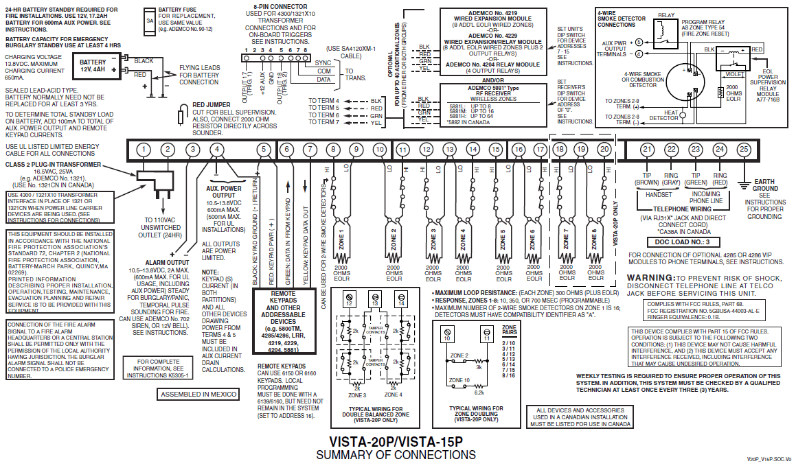
For more manuals by Honeywell, visit ManualsLibraryy
Honeywell VISTA-20PCN Programming Alarm System-FAQs
How do I add a user code on the VISTA-20P?
To add a new user code, press [8], enter the user number (e.g., 03), and then enter the new 4-digit code. A single beep confirms that the code was successfully added.
How many wireless zones does the VISTA-20P support?
The VISTA-20P supports up to 64 zones total: up to 48 hardwired and up to 56 wireless zones (with a wireless receiver). It also supports up to 16 key fob zones.
How do I exit programming mode on the VISTA-20P?
Press [*98] to exit programming mode. This also prevents re-entry using the installer code and [800].
How can I enter programming mode on the Honeywell VISTA-20P?
Use the default installer code [4112] followed by [800]. If the code is lost, use the backdoor method by pressing and holding [*] and [#] within 50 seconds of powering the system on.
What frequency does the VISTA-20P system use?
The system uses 345 MHz for wireless devices. Hardwired contacts can be used without additional equipment, but a wireless receiver is required for wireless devices.
How do I connect the VISTA-20P to Wi-Fi?
To connect wirelessly, add an IP communicator to the system and use an Ethernet-to-Wi-Fi bridge to link the system to your Wi-Fi network.
How do I bypass a zone on the VISTA-20P?
Enter your 4-digit user code, press [6] (Bypass), and then enter the 2-digit zone number (use 0 before single digits, e.g., 02). The keypad will briefly show a message for each bypassed zone.
What is the default master code for the VISTA-20P?
The default master code is [1234], which should be changed for better security. For system programming, use the installer code [4112].

