
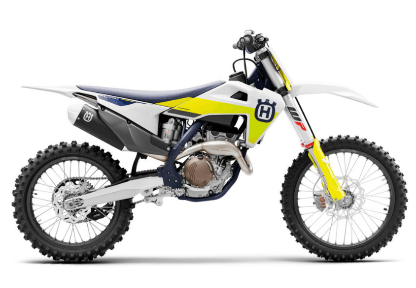
Husqvarna FC 250 Bike
IMPORTANT NOTES
Manufacturer and implied warranty
The work prescribed in the service schedule must be carried out by an authorized Husqvarna Motorcycles workshop only and confirmed both in the customer’s Service & Warranty Booklet and the Husqvarna Motorcycles Dealer.net; otherwise, all warranty claims will be void. Damage or secondary damage caused by tampering with and/or conversions on the vehicle are not covered by the warranty. Additional information on the manufacturer or implied warranty, and the procedures involved, can be found in the Service & Warranty Booklet.
Spare parts, accessories
For your safety, only use spare parts and accessory products that are approved and/or recommended by Husqvarna Motorcycles and have them installed by an authorized Husqvarna Motorcycles workshop. Husqvarna Motorcycles accepts no liability for other products and any resulting damage or loss. The article numbers of some spare parts and accessory products are specified in parentheses in the descriptions. Your authorized Husqvarna Motorcycles dealer will be glad to advise you.
The current Husqvarna Motorcycles accessories for your vehicle are available from your authorized Husqvarna Motorcycles dealer and on the Husqvarna Motorcycles website. International Husqvarna Motorcycles website: www.husqvarna-motorcycles.com
Service
A prerequisite for perfect operation and prevention of premature wear is that the service, care, and tuning work on the engine and chassis is properly carried out as described in the Owner’s Manual. Incorrect adjustment and tuning of the engine and chassis can lead to damage and breakage of components.
Use of the vehicle under difficult conditions, such as on sand or on wet and muddy surfaces, can lead to con- considerably more rapid wear of components such as the drive train, brake system, or suspension components.
For this reason, it may be necessary to inspect or replace parts before the next scheduled service. You must adhere to the stipulated run-in times and service intervals. If you observe these exactly, you will ensure a much longer service life for your motorcycle.
Figures
The figures contained in the manual may depict special equipment. In the interest of clarity, some components may be shown disassembled or may not be shown at all. It is not always necessary to disassemble the component to perform the activity in question. Please follow the instructions in the text.
Customer service
Your authorized Husqvarna Motorcycles dealer will be happy to answer any questions you may have regarding your vehicle and Husqvarna Motorcycles.
A list of authorized Husqvarna Motorcycles dealers can be found on the Husqvarna Motorcycles website. International Husqvarna Motorcycles website: www.husqvarna-motorcycles.com
VIEW OF VEHICLE
View of vehicle, front left (example)
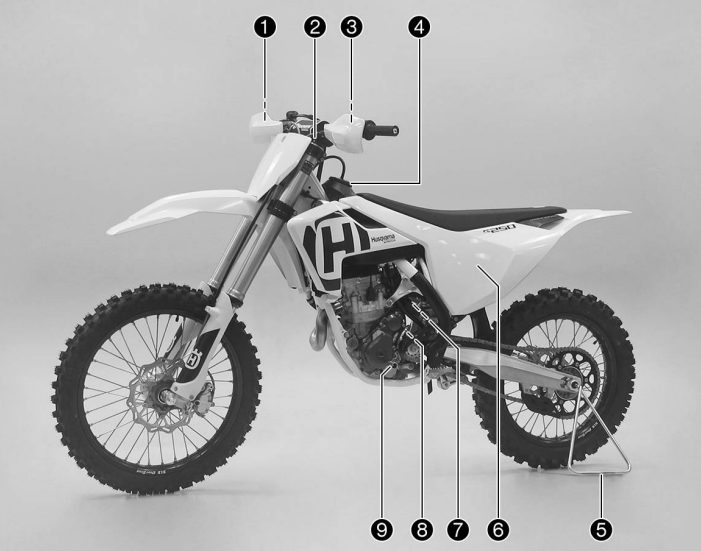
- Hand brake lever ( p. 15)
- Fork air pressure adjustment
- Clutch lever ( p. 15)
- Filler cap
- Plug-in stand ( p. 20)
- Air filter box cover
- Cold start button ( p. 18)
- Engine number ( p. 13)
- Shift lever ( p. 19)
View of vehicle, rear right (example)
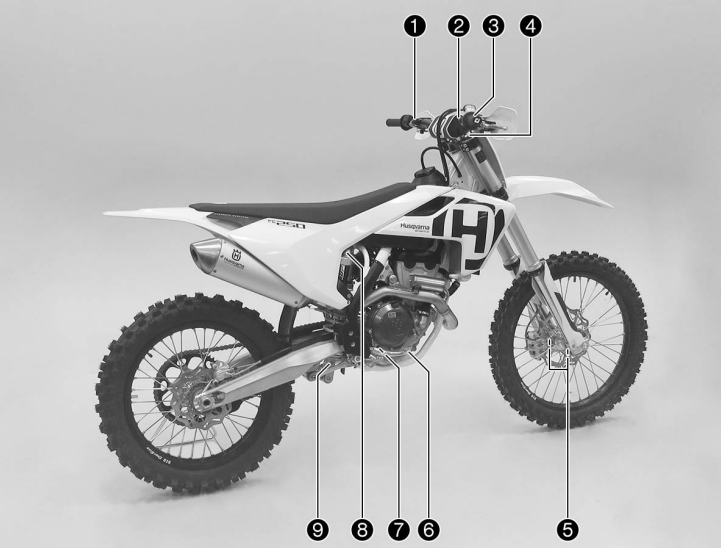
- Kill switch ( p. 16)
- Electric starter button ( p. 16)
- Throttle grip ( p. 15)
- Fork compression adjustment
- Fork article number ( p. 13)
- Foot brake lever ( p. 20)
- Engine oil level viewer
- Shock absorber compression adjustment
- Shock absorber rebound adjustment
SERIAL NUMBERS
Chassis number
The chassis number ![]() is stamped on the right side of the steering head.
is stamped on the right side of the steering head.
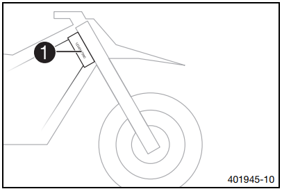
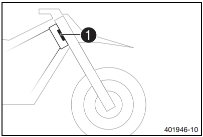
Type label
The type label ![]() is fixed to the front of the steering head.
is fixed to the front of the steering head.
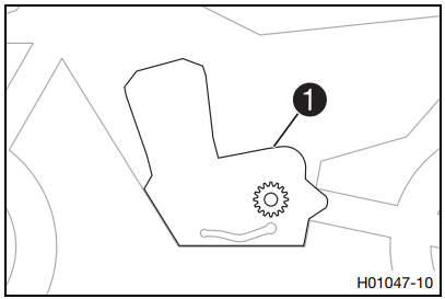
Engine number
The engine number ![]() is embossed on the left side of the engine over the engine’s sprocket.
is embossed on the left side of the engine over the engine’s sprocket.
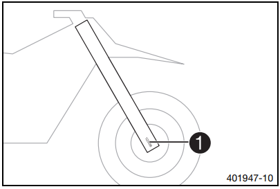
For the article number.
The fork article number ![]() is stamped on the inside of the axle clamp.
is stamped on the inside of the axle clamp.
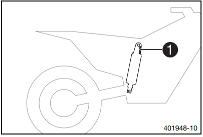
Shock absorber article number
The shock absorber article number ![]() is stamped on the top of the shock absorber above the adjusting ring towards the engine side.
is stamped on the top of the shock absorber above the adjusting ring towards the engine side.
CONTROLS
Clutch lever
The clutch lever ![]() is fitted on the left side of the handlebar. The clutch is hydraulically operated and self-adjusting.
is fitted on the left side of the handlebar. The clutch is hydraulically operated and self-adjusting.
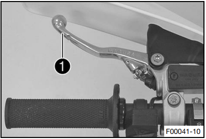
Hand brake lever
(Option: Brembo)
The hand brake lever ![]() is fitted on the right side of the handlebar.
is fitted on the right side of the handlebar.
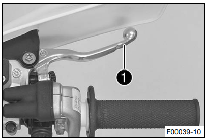
(Option: Magura)
The hand brake lever ![]() is fitted on the right side of the handlebar.
is fitted on the right side of the handlebar.
The front brake is engaged using the hand brake lever.
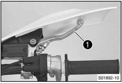
Throttle grip
The throttle grip ![]() is fitted on the right side of the handlebar.
is fitted on the right side of the handlebar.
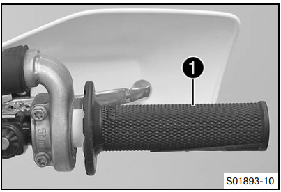
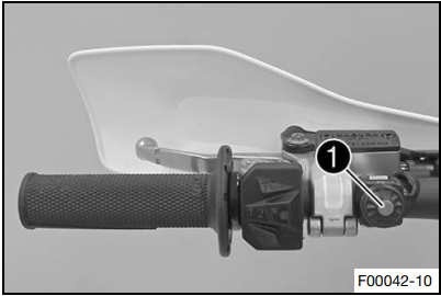
Kill switch
The kill switch ![]() is fitted on the left side of the handlebar.
is fitted on the left side of the handlebar.
Possible states
- Kill switch
 in the basic position – In this position, the ignition circuit is closed, and the engine can be started.
 - Kill switch
 pressed – In this position, the ignition circuit is interrupted, a running engine stops, and a non-running engine will not start.
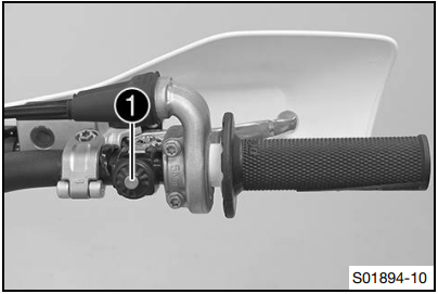
Electric starter button
The electric starter button ![]() is fitted on the right side of the handlebars.
is fitted on the right side of the handlebars.
Possible states
- Electric starter button
 in basic position
 - Electric starter button
 pressed – In this position, the electric starter is actuated.
Combination switch
The combination switch is fitted on the left side of the handlebar.
Possible states
- 1: STANDARD – STANDARD mapping is activated when LED 1 lights up.
- 1TC: STANDARD with TC – STANDARD mapping with traction control is activated when LED 1 and TC light up.
- 2: ADVANCED – ADVANCED mapping is activated when LED 2 lights up.
- 2TC: ADVANCED with TC – ADVANCED mapping with traction control is activated when LED 2 and TC light up.
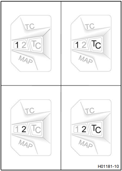
The engine characteristic can be changed using the MAP button on the combination switch.
The launch control and the traction control can also be activated using the combination switch.
Overview of indicator lamps
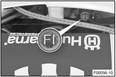
Possible states
 Malfunction indicator lamp lights up/flashes orange – The OBD has detected an error in the vehicle electronics. Come safely to a halt, and contact an authorized Husqvarna Motorcycles workshop.
 Malfunction indicator lamp flashes orange rapidly – Launch control is activated.
Opening the filler cap
Danger
Fire hazard: Fuel is highly flammable.
The fuel in the fuel tank expands when warm and can escape if overfilled.
- Do not refuel the vehicle in the vicinity of open flames or lit cigarettes.
- Switch off the engine for refueling.
- Make sure that no fuel is spilled, particularly not on hot parts of the vehicle.
- If any fuel is spilled, wipe it off immediately.
- Observe the specifications for refueling.
Warning
The danger of poisoning Fuel is poisonous and a health hazard.
- Avoid skin, eye, and clothing contact with fuel.
- Immediately consult a doctor if you swallow fuel.
- Do not inhale fuel vapors.
- In case of skin contact, rinse the affected area with plenty of water.
- Rinse the eyes thoroughly with water, and consult a doctor in case of fuel contact with the eyes.
- Change your clothing in case of fuel spills on them.
- Keep fuels correctly in a suitable canister and out of the reach of children.
Warning
Environmental hazard: Improper handling of fuel is a danger to the environment.
- Do not allow fuel to enter the groundwater, the soil, or the sewage system.
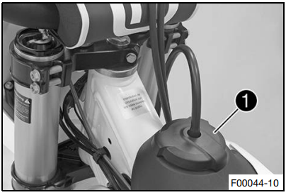
- Turn the filler cap
 counterclockwise and lift it off.
Closing the filler cap
Mount the filler cap![]() and turn it clockwise until the fuel tank is tightly closed.
and turn it clockwise until the fuel tank is tightly closed.
![]() Info
Info
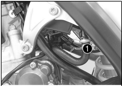
Run the fuel tank breather hose ![]() without kinks.
without kinks.
Cold start button
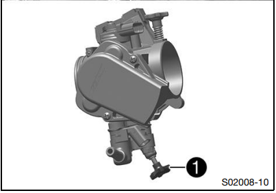
The cold start button ![]() is fitted on the bottom of the throttle valve body.
is fitted on the bottom of the throttle valve body.
The injection system extends the injection time if the engine is cold and the outside temperature is low. To help the engine burn the increased amount of fuel, it must be supplied with additional oxygen by pushing the cold start button.
After briefly opening up the throttle and then releasing the throttle grip again, or turning the throttle grip towards the front, the cold start button returns to its original position.
![]() Info
Info
Check whether the cold start button has returned to its basic position.
Possible states
- The cold start button is activated – The cold start button is pushed in all the way.
- The cold start button is deactivated – The cold start button is in its basic position.
Idle speed adjusting screw
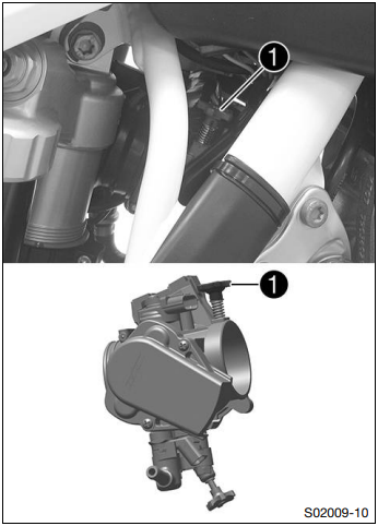
The idle setting of the throttle valve body has a big influence on the vehicle’s starting behavior, on stable idling, and on vehicle response when the throttle is opened.
An engine with a correctly set idle speed is easier to start than an engine with the idle speed set incorrectly.
The idle speed is adjusted with idle speed adjusting screw ![]() . Increase the idle speed by turning the idle speed adjusting screw clockwise.
. Increase the idle speed by turning the idle speed adjusting screw clockwise.
Decrease the idle speed by turning the idle speed adjusting screw counterclockwise.
Shift lever
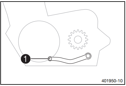
The shift lever ![]() is mounted on the left of the engine.
is mounted on the left of the engine.
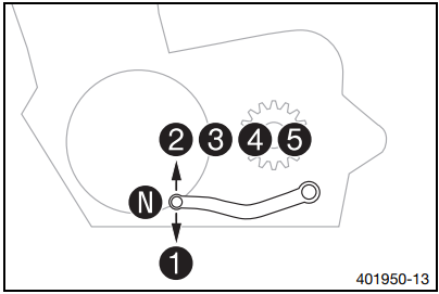
The gear positions can be seen in the figure.
The neutral or idle position is between the first and second gears.
Foot brake lever
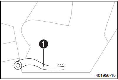
The foot brake lever ![]() is located in front of the right footrest. The foot brake lever is used to activate the rear brake.
is located in front of the right footrest. The foot brake lever is used to activate the rear brake.
Plug-in stand
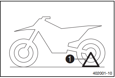
The holder for the plug-in stand ![]() is on the left side of the wheel spindle.
is on the left side of the wheel spindle.
The plug-in stand is used to park the motorcycle.
![]() Info
Info
Remove the plug-in stand before starting on a trip.
Service hour counter
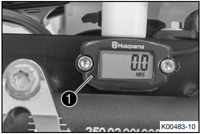
The service hour counter ![]() is fitted in front of the handlebars. It shows the total number of service hours of the engine. The service hour counter begins counting when the engine is started and stops when the engine is switched off.
is fitted in front of the handlebars. It shows the total number of service hours of the engine. The service hour counter begins counting when the engine is started and stops when the engine is switched off.
![]() Info
Info
It is not possible to delete or adjust anything on the service hour counter.
CLEANING, CARE
Cleaning the motorcycle
Note
Material damage: Components become damaged or destroyed if a pressure cleaner is used incorrectly.
The high pressure forces water into the electrical components, connectors, throttle cables, and bearings, etc. Pressure that is too high causes malfunctions and destroys components.
- Do not direct the water jet directly onto electrical components, connectors, throttle cables, or bearings.
- Maintain a minimum distance between the nozzle of the pressure cleaner and the component. Minimum clearance 60 cm (23.6 in)
Warning
Environmental hazard: Hazardous substances cause environmental damage.
- Dispose of oils, grease, filters, fuel, cleaning agents, brake fluid, etc., correctly and in compliance with the applicable regulations.
![]() Info
Info
If you clean the motorcycle regularly, its value and appearance will be maintained over a long period. Avoid direct sunshine on the motorcycle during cleaning.
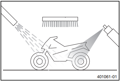
- Close off the exhaust system to keep water from entering.
- First, remove coarse dirt particles with a gentle spray of water.
- Spray very dirty areas with a normal motorcycle cleaner and then clean with a paintbrush.
![]() Info
Info
Use warm water containing normal motorcycle cleaner and a soft sponge.
Never apply motorcycle cleaner to a dry vehicle; always rinse the vehicle with water first.
- After rinsing the motorcycle with a gentle spray of water, allow it to dry thoroughly.
- Remove the closure of the exhaust system.
Warning
Danger of accidents. Moisture and dirt impair the brake system.
Brake carefully several times to dry out and remove dirt from the brake linings and the brake discs.
- After cleaning, ride a short distance until the engine reaches operating temperature.
![]() Info
Info
The heat produced causes water at inaccessible locations in the engine and on the brake system to evaporate.
- Push back the protection caps of the handlebar controls to allow any water that has penetrated to evaporate.
- After the motorcycle has cooled off, lubricate all moving parts and bearings.
- Clean the chain. ( p. 68)
- Treat bare metal parts (except for brake discs and the exhaust system) with a corrosion inhibitor.
Preserving materials for paints, metal, and rubber ( p. 139) - Treat all plastic parts and powder-coated parts with a mild cleaning and care agent.
TROUBLESHOOTING
The engine does not turn when the electric starter button is pressed
Possible cause
- Operating error
- Battery discharged
- Main fuse blown
- Faulty starter relay
- Faulty starter motor
Action
- Carry out the start procedure. (p. 26)
- Recharge the battery. (p. 102)
- Check the charging voltage.
- Check the open-circuit current.
- Check the stator winding of the alternator.
- Change the main fuse. (p. 104)
- Check the starter relay.
- Check the starter motor.
The engine turns but does not start
Possible cause
- The plug-in connection of the fuel line is not connected
- The fuel screen in the fuel hose connection is clogged
- The idle speed is not set correctly
- A spark plug is oily or wet
- The electrode distance (plug gap) of the spark plug is too wide
- Short circuit cable in wiring harness frayed, kill switch defective
- Defect in the fuel injection system
Action
- Connect the plug-in connection of the fuel line.
- Change the fuel screen. ( p. 116)
- Adjust the idle speed. (p. 113)
- Clean and dry the spark plug, or change it if necessary.
- Adjust the plug gap. Guideline Spark plug electrode gap 0.8 mm (0.031 in)
- Check the wiring harness. (visual check)
- Check the electrical system.
- Read out the fault memory using the Husqvarna Motorcycles diagnostics tool.
The engine does not speed up
Possible cause
- Defect in the fuel injection system
Action
- Read out the fault memory using the Husqvarna Motorcycles diagnostics tool.
The engine dies during the trip
Possible cause
- Lack of fuel
Action
- Refuel.
Engine overheats
Possible cause
- Too little coolant in the cooling system
- Too little air stream
- Radiator fins are very dirty
- Foam formation in the cooling system
- Bent radiator hose
Action
- Check the cooling system for leakage.
- Check the coolant level. ( p. 107)
- Switch off the engine when standing.
- Clean the radiator fins.
- Drain the coolant. ( p. 108)
- Refill with coolant. ( p. 108)
- Change the radiator hose.
Battery discharged
Possible cause
- The battery is not charging
- Unwanted power consumer
Action
- Check the charging voltage.
- Check the stator winding of the alternator.
- Check the open-circuit current.
The malfunction indicator lamp lights up or flashes
Possible cause
- Defect in the fuel injection system
Action
- Check the cabling for damage and the electrical plug-in connections for corrosion and damage.
- Read out the fault memory using the Husqvarna Motorcycles diagnostics tool.
High oil consumption
Possible cause
- The engine vent hose is bent
- The engine oil level is too high
- Engine oil is too thin (low viscosity)
- Piston or cylinder worn
Action
- Route the vent hose without bends or change it if necessary.
- Check the engine oil level. ( p. 117)
- Change the engine oil and oil filter, and clean the oil screen. ( p. 118)
- Measure the piston/cylinder mounting clearance.
The engine has too little power.
Possible cause
- The air filter is very dirty.
- The fuel filter is very dirty.
- Defect in the fuel injection system
- The exhaust system is leaky, deformed, or has too little glass fiber yarn filling in the main silencer.
- The valve clearance is too little
Action
- Clean the air filter and air filter box. ( p. 62)
- Change the fuel filter.
- Read out the fault memory using the Husqvarna Motorcycles diagnostics tool.
- Check the exhaust system for damage.
- Change the glass fiber yarn filling of the main silencer. ( p. 64)
- Adjust the valve clearance.
For more manuals by Husqvarna, visit ManualsLibraryy.
Husqvarna FC 250 Bike- FAQs
What type of bike is the Husqvarna FC 250?
The Husqvarna FC 250 is a motocross bike with a 250cc 4-stroke engine, designed for competitive off-road racing.
Where is the Husqvarna FC 250 manufactured?
Husqvarna motorcycles are produced in Mattighofen, Austria.
Is the Husqvarna FC 250 street legal?
No, it is a competition-only motocross bike and not designed for road use.
What is the horsepower of the FC 250?
The 2025 model produces ~40.7 HP (measured at the rear wheel).
Does the FC 250 have a quick shifter?
Yes, it features a quickshifter for smooth upshifts without using the clutch.
What is the top speed of the FC 250?
Approximately 125 km/h (78 mph), depending on gearing and terrain.
Is the FC 250 fuel-injected?
Yes, it has electronic fuel injection (EFI) for optimal performance.
What fuel should I use?
Use premium unleaded gasoline (95+ RON) for best performance.
What type of frame does the FC 250 have?
A chromium molybdenum steel frame for lightweight durability.
What is the fuel tank capacity?
1.9 gallons (7.2 liters).
What suspension does it use?
Front: WP XACT 48mm forks (adjustable)
Rear: WP XACT monoshock (fully adjustable)

 Malfunction indicator lamp lights up/flashes orange – The OBD has detected an error in the vehicle electronics. Come safely to a halt, and contact an authorized Husqvarna Motorcycles workshop.
 Malfunction indicator lamp flashes orange rapidly – Launch control is activated.