JLG Sky Trak MMV Telehandler
Safety Practices
TRAINING MECHANICS AS OPERATORS
Because it is necessary to move the vehicle to service or maintain the vehicle, it is necessary that all mechanics are OSHA trained and certified as operators. A mechanic trained in the proper operation of the vehicle can better determine whether all the functions are operating correctly. At the time of original purchase, the purchaser of this vehicle was instructed by the seller on its proper use. When this vehicle is to be serviced or maintained by someone other than the purchaser, make certain that the mechanic is trained, by the OSHA regulations listed in the NOTICE below, and reads and understands the Sky Trak MMV Telescopic Material Handler Owners/Operators Manual before operating or maintaining the vehicle.
NOTICE: Under OSHA rules, it is the responsibility of the employer to provide operator training. Successful completion and certification of Safety Training for Rough Terrain Forklifts is required. Operator Training Kits are available by calling Ken Cook Company at (414) 466-6060. An order form for these kits is available on our website at http://www.jlg.com.
In addition, make sure that the mechanic has completed a walk-around inspection of the vehicle, is familiar with all decals and/or decal plates on the vehicle, and has demonstrated the correct use of all controls.
SAFETY INFORMATION
The following information provides general safety instructions, including examples of hazard statements with signal words, notification of hazards, methods to help avoid hazards and the consequences of failing to follow the Safety information. To avoid possible death or injury, Carefully read and follow all safety messages. Fully understand the potential causes of death or injury. In the event of an accident, know where to obtain medical assistance, use a first-aid kit, and fire extinguisher/fire suppression system. Keep emergency telephone numbers (fire department, ambulance, rescue squad/paramedics, police department, etc.) nearby. If working alone, check with another person routinely to help ensure personal safety. The information in this manual does not replace any other safety rules or proper judgment. Governmental authorities and employers also have their own sets of rules, codes, regulations, and laws. Before starting work at a worksite, check with the supervisor or safety coordinator and ask about the safety policy. Learn the safety requirements in effect before operating, maintaining, servicing, or testing the vehicle. Safety depends on following safety requirements.
General Information, Specifications, and Maintenance
MMV COMPONENT TERMINOLOGY
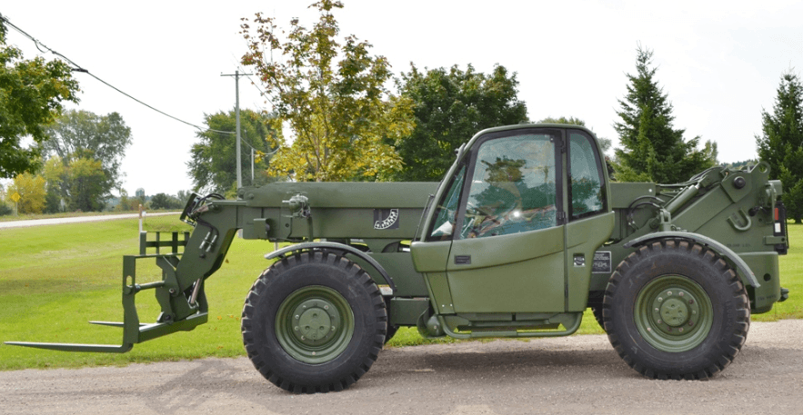
To understand the safety, operation, and maintenance information presented in this manual, the operator/mechanic must be familiar with the name and location of the major assemblies on this vehicle. The following illustration identifies the components that are referred to throughout this manual.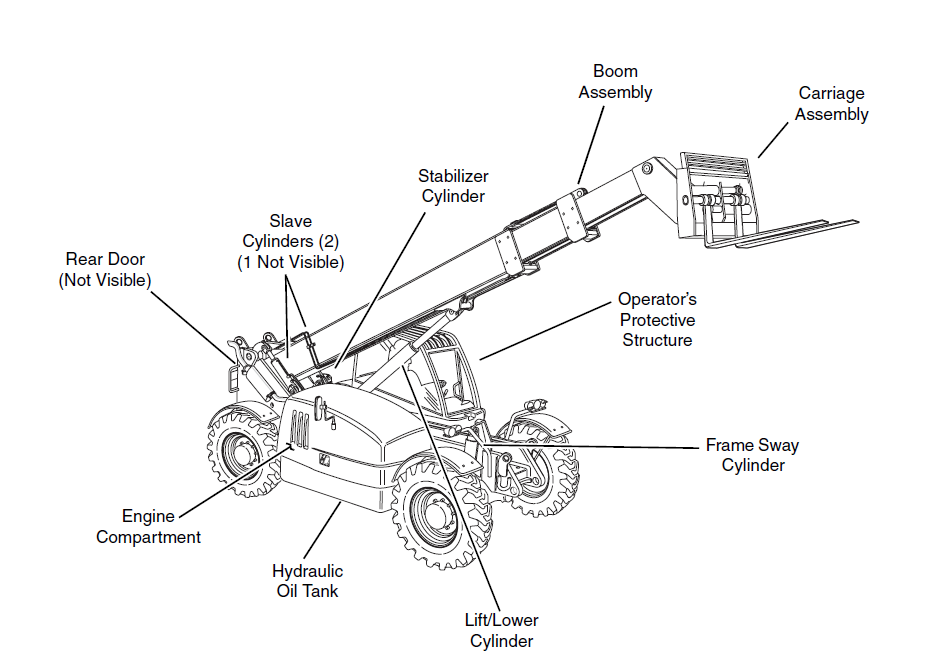
INTRODUCTION
Service Methods
Appropriate service methods and proper repair procedures are essential for safe, reliable operation of this vehicle and the safety of the individual doing the work. This Service Manual provides general direction for accomplishing service and repair work with tested, effective techniques. Following them will assure reliability. There are many variations in procedures, techniques, tools, and parts for servicing vehicles, as well as work skills. This Manual cannot possibly anticipate all such variations and provide advice or cautions for each one. Accordingly, anyone who intends to depart from the instructions in this Manual must first consider personal safety and then vehicle integrity.
IMPORTANT: JLG recommends the use of environmentally sound waste storage and disposal practices. NEVER drain fluids on the ground or into a sewer or catch basin. Use suitable collection containers, then store and/or dispose of waste products in an approved and safe manner. Check and obey all Federal, State, and/or Local regulations regarding waste storage, disposal, and recycling.
The Owners/Operators Manual
The Owner’s/Operator’s Manual provides information you need to properly operate and maintain this vehicle.
IMPORTANT: Before you operate this vehicle, read the manual completely and carefully, so that you will understand the safety instructions and the operation of the controls and safety equipment. You must comply with all Danger, Warning, and Caution notices. They are for your benefit. All references to the right side, left side, front, and rear are given from the operator’s seat looking in a forward direction.
Replacement Parts and Warranty Information
For reference, when ordering replacement parts or making service inquiries about the vehicle, the vehicle serial number is required to help assure the provision of correct parts and information. Before ordering parts or initiating service inquiries, make note of the serial number. The vehicle serial number plate (1) is located on the front of the main frame.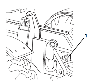
IMPORTANT: The replacement of any part on this vehicle with any other than a JLG authorized replacement part can adversely affect the performance, durability, or safety of the vehicle and will void the warranty. JLG disclaims liability for any claims or damages, whether regarding property damage, personal injury, or death, arising out of the use of unauthorized replacement parts. A warranty registration form must be filled out by the JLG Authorized Service Center (ASC), signed by the purchaser, and returned to JLG when the vehicle is sold and/or put into use. Registration activates the warranty period and helps to assure that warranty claims are promptly processed. To guarantee full warranty service, verify that the distributor has returned the business reply card of the warranty registration form to JLG.
Disclaimer
JLG reserves the right to make changes to and to add improvements upon its product at any time, without public notice or obligation. JLG also reserves the right to discontinue manufacturing any product at its discretion at any time.
TORQUES
Fasteners
All fasteners (nuts, bolts, washers, etc.) are equal to SAE Grade 5 (PC8.8) and are plated, unless otherwise specified.
Bolts and Nuts
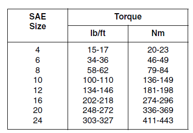
Unless otherwise specified, the following values apply for Grade 5 (PC8.8) nuts and bolts: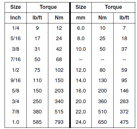
Straight Thread O-ring Fitting (Non-Adjustable)
When the vehicle leaves the factory, it is equipped only with straight thread o-ring fittings. Customer-added accessories may differ; therefore, consult the manufacturer’s product literature for information.
- Verify that both threads and sealing surfaces are free of burrs, nicks, scratches, and any foreign material.
- Lubricate the new o-ring with a light coating of hydraulic oil.
- Tighten fitting to the proper torque according to the following chart:

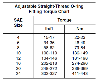
Straight Thread O-ring Fitting (Adjustable)
When the vehicle leaves the factory, it is equipped only with straight thread o-ring fittings. Customer-added accessories may differ; therefore, consult the manufacturer’s product literature for information.
- Verify that both mating parts are free of burrs, nicks, scratches, and any foreign material.
- Lubricate the new o-ring with a light coat of hydraulic oil.
- Back off the locknut as far as possible.
- Screw the fitting into the port by hand until the backup washer contacts the face of the port and is pushed all the way towards the locknut.
- To position the fitting, unscrew by the required amount, but not more than one full turn.
- Hold the fitting in the desired position and tighten to the proper torque according to the following chart:

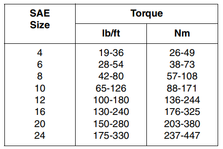
Flat-Face O-ring Fittings
When the vehicle leaves the factory, it is equipped only with straight thread o-ring fittings. Customer-added accessories may differ; therefore, consult the manufacturer’s product literature for information. Improper assembly of this type of joint will result in a leaking joint. Under-tightening will result in the joint loosening during normal use. Foreign material on either sealing surface will cause damage to one or both mating parts when the joint is tightened, resulting in a leaking joint. The absence of the fitting o-ring will cause the joint to leak.
- Verify that both threads and sealing surfaces are free of burrs, nicks, scratches, and any foreign material.
- Inspect the male fitting for the presence of the o-ring seal. Replace the o-ring if missing or damaged.
- Place the flat surface of the female connector in full contact with the o-ring in the male connector.
- Finger-tighten the nut onto the fitting
- Hold the fitting in the desired position. For hoses and swivel fittings, use a second wrench to keep the female connector from moving during tightening. Tighten to the proper torque according to the following chart:

SPECIFICATIONS
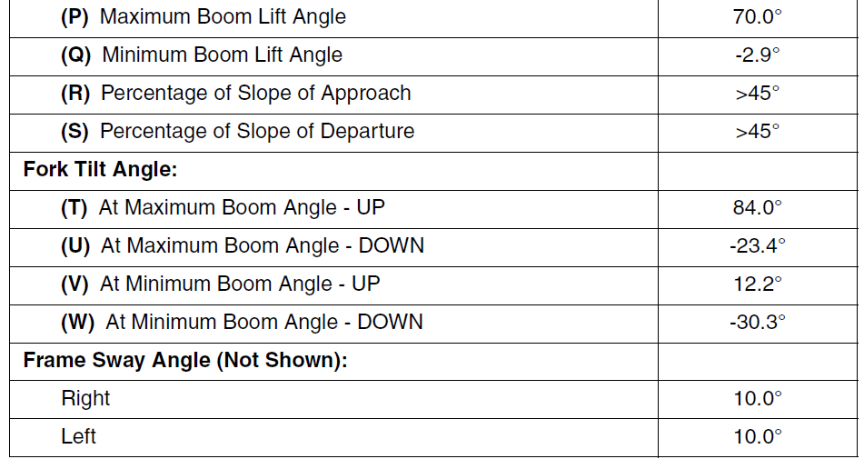
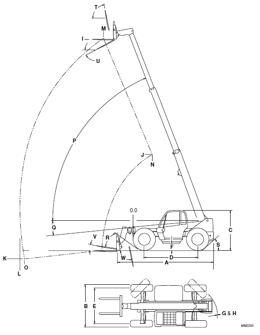
Vehicle Dimensions
With 15.50-25 Radial Tires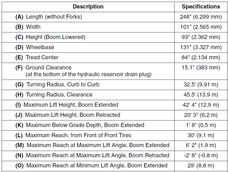
Cab, Covers, and Mirrors
OPERATOR’S CAB AND COVERS COMPONENT TERMINOLOGY
To understand the safety, operation and maintenance information presented in this section, it is necessary that the operator/mechanic be familiar with the name and location of the major assemblies of the vehicle cab and covers. The following illustration identifies the components that are referred to throughout this section.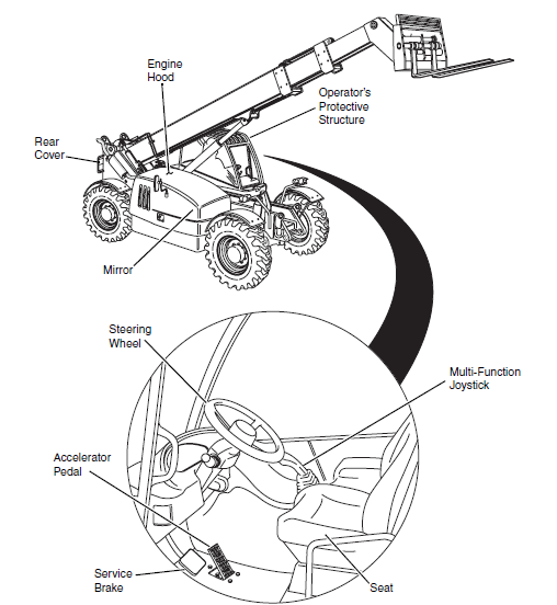
OPERATOR’S CAB
Operator’s Cab Description
The welded metal cab features European styling and a modular design, allowing for a relatively quick, simple exchange of the entire cab and/or component parts. The cab is bolted to the cab mount, which in turn is bolted to the frame. The cab is set up as an enclosed cab configuration. The enclosed cab includes a heater/window defroster system, and windshield, roof, and rear window wipers. The operator’s cab is a protective structure. The cab itself contains roll-over protective and falling object protective structures (ROPS/FOPS) for the operator.
WARNING: he protection offered by this ROPS/FOPS will be impaired if subjected to any modification or structural damage, at which time replacement is necessary. ROPS/FOPS must be properly installed using fasteners of the correct size and grade, and torqued to their specified value.
DO NOT weld, grind, drill, repair, or modify the cab in any way. Any modification or damage to the cab’s structural components requires a cab replacement. The lives of the operator and others are potentially at stake. To help ensure optimum safety, protection, and performance, replace the cab if it is damaged. Refer to the appropriate parts manual for ordering information. The cab contains the seat, operating controls, numerous panels, steering and brake components, and more. Covers and mirrors on the vehicle exist for safety, protection, and appearance. They are relatively simple to remove and replace.
Serial Number Decal
The cab serial number decal (1) is located on the left side of the cab, behind the seat. Information specified on the serial number plate includes the cab model number, the cab serial number, and other data. Write this information down in a convenient location to use in cab correspondence.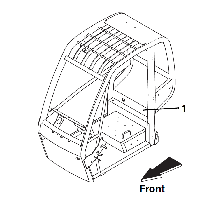
Cab Maintenance
Replacement
WARNING: risk of death or serious personal injury. NEVER modify, weld or drill the cab.
WARNING: The protection offered by this ROPS/FOPS will be impaired if subjected to any modification or structural damage, at which time replacement is necessary. ROPS/FOPS must be properly installed using fasteners of the correct size and grade, and torqued to their specified value.
IMPORTANT: To help ensure safety and optimum performance, replace the cab if it is damaged. Refer to the appropriate parts manual for ordering information. Before performing any inspection, maintenance or service operation, thoroughly clean the vehicle. DO NOT spray water or cleaning solution in, on, near or around the operator’s dash panels and electrical components. Inspect the cab, its welds, and mounts. If modification, damage, a cracked weld and/or fatigued metal is discovered, replace the cab. Contact the JLG Service Department or the local JLG Authorized Service Center (ASC) with any questions about the suitability or condition of a cab.
Cab Removal
WARNING: Wear protective footwear with reinforced toe caps and slip-resistant soles. Failure to comply can result in foot injury from falling objects or other bodily injury from slipping or falling.
WARNING: Never lift a heavy object without the help of at least one assistant or a suitable sling or hoist. Failure to comply can result in death or serious personal injury.
IMPORTANT: Remove and label cab panels and other components as needed before removing the cab from the vehicle. Label, disconnect, and cap hydraulic hoses. Transfer the cab parts to the replacement cab after the replacement cab is securely mounted on the vehicle.
- Park the vehicle on a firm, level surface. Allow sufficient overhead and side clearance for cab removal. Level the vehicle, ground the attachment, place the travel select lever in the [N] NEUTRAL position, place the neutral lock lever in the [N] NEUTRAL LOCK position, engage the parking brake switch, and shut the engine OFF. Open the engine hood. Allow the engine and hydraulic fluid to cool.
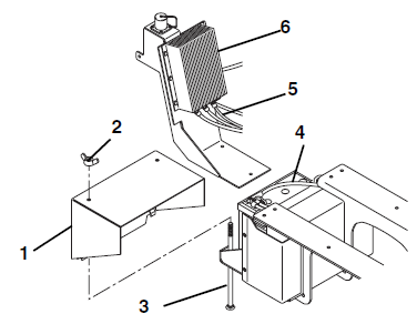
- Remove engine side battery box cover (1). Remove wing nut (2) and carriage bolt (3,) and set cover and mounting hardware aside for later re-assembly.
- Disconnect the negative (-) battery cable (4) at the negative (-) terminal on the battery in the engine side battery box.
- Disconnect the negative (-) cable (5) at the bottom of the battery equalizer (6).
- Remove the joystick assembly (refer to Section 3.5.2, b. Joystick Assembly Replacement. Label, disconnect and cap the six hydraulic hoses mounted at the base of the joystick assembly.

- Drain coolant from the radiator (refer to Section 2.13.4, b. Drain and Flush the Radiator. The coolant capacity is approximately 3 gallons (11,4 liters). Allow the coolant to drain into a clean container and save for putting back into the radiator at a later time.
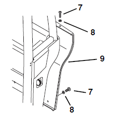
- Working from the outside rear of the cab, remove the four button head capscrews (7) and flat plastic washers (8) and remove the rear cab panel (9).

- Remove the seat assembly from the seat support (refer to Section 3.3.2, Seat Replacement). Remove the two elastic locknuts and rebound washers from the rear of the cab and leave the tethers attached to the seat.
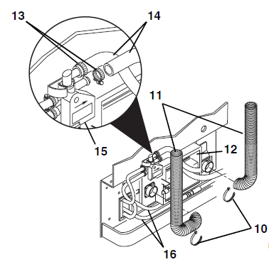
- On the back side of the cab, clip the two tie wraps. (10) Securing the two flexible heater hoses (11) to the plenum (12).

- Loosen both hose clamps (13) securing the heater hoses (14) to the heater valve (15). Disconnect and label both hoses.
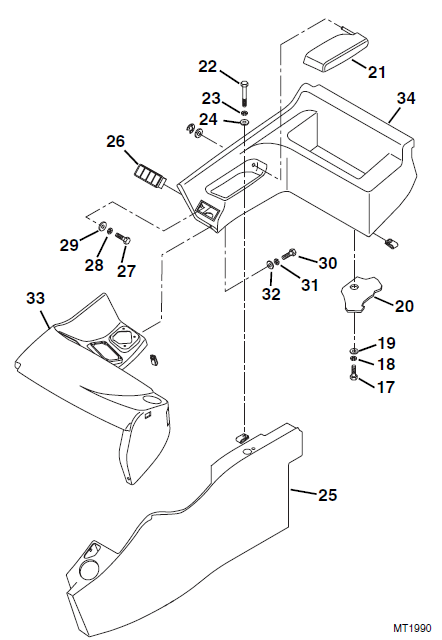
IMPORTANT: Before the cab can be removed from the vehicle, the air conditioning hoses (16) need to be disconnected from the heater/air conditioning blower beneath the seat. This procedure must be completed by an authorized air conditioning service technician. This service technician will also need to be available when the cab is reinstalled to reinstall the air conditioning hoses to the heater/air conditioning blower. - Remove two capscrews (17), lockwashers (18), and rebound washers (19) from the rear of the cab (20).
- Open the armrest (21) and remove cthe apscrew (22), lockwasher (23), and rebound washer (24) securing the rear tool bin (34) to the console support (25).
- Carefully pry the switch bezel assembly (26) out of the panel. Label and disconnect the switch wiring connector(s).
- Remove capscrew (27), lockwasher (28), and flat washer (29), securing the rear tool bin (34) to the side of the cab.
- Remove capscrew (30), lockwasher (31), and rebound washer (32), securing the rear tool bin (34) to the front dash (33).
- Remove rear tool bin (34).

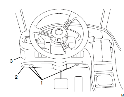
- Remove the three self-drilling screws (1) (one screw is not visible in illustration) securing the lower dash cover (2) to the front dash (3).
- Remove the lower dash cover (2).

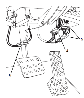
- Label and disconnect the transmission range selector switch wiring connector (4), turn signal/lights wiring connectors (5), and brake switch connector (6).

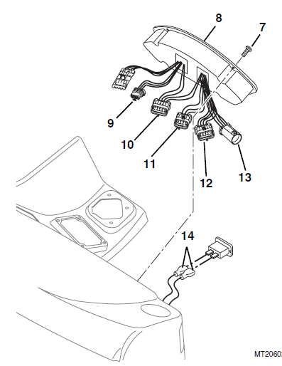
- Remove the four bution head screws (7) from the display panel (8) in the front dash. Carefully pull the display panel forward and lay it aside.
- Label and disconnect the 8-pin male (9), 10-pin gray female (10), 8-pin female (11), 10-pin black female (12), and 7-pin female (13) display panel connectors from the harness and remove the display panel from the front dash.

- Remove the four screws securing the logic panel to the side console. Carefully lift the logic panel from the side console and tag the wire connectors as they are removed. Remove the logic panel from the side console. Save all hardware for reassembly.
- Working through the display panel opening, label and disconnect the wiring connectors (14) at the hourmeter.
Electrical System
ENGINE START CIRCUIT
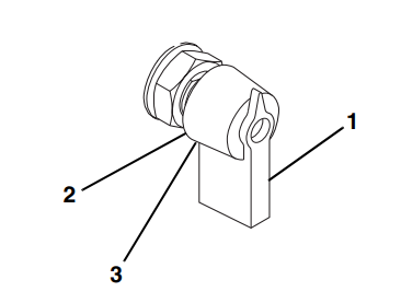
The purpose of the engine start circuit is to energize the starter solenoid and engage the starter motor to start the engine. To start the engine, the ignition switch (1) must be in the START (2) position, the parking brake switch must be in the ON position, and the transmission shift control switch (travel select lever) must be in the NEUTRAL (center) position. When the ignition switch is turned to the START (2) position, and with the transmission in NEUTRAL (N), the starting circuit activates the starter relay, starter solenoid, and fuel shutoff solenoid. The fuel shutoff solenoid opens a valve that supplies fuel to the injection pump.
Starting Circuit
The starting circuit functions as follows:
- 24V direct current from the battery flows through the Positive (+) battery cable to the starter solenoid.
- 12V direct current also flows through the ignition Switch the circuit breaker and the ignition switch.
- When the ignition is pushed IN and turned to the START (2) position, current flows through the contacts in the ignition switch, through the fuse panel, to the parking brake switch.

- If the parking brake is set, current flows through contacts in the brake switch to the neutral engage relay.
- If the transmission select lever is in NEUTRAL (N), current flows through the neutral engage relay to energize the coil of the engine start relay. (This closes the contacts in the engine start relay.) The engine start relay contacts close, and current flows to the engine start solenoid. (The flow of current closes internal contacts in the engine start solenoid that allow current to flow through the starter solenoid.) The. engine start solenoid coil energizes and its contacts close, allowing current to flow 0 the starter motor.
- The starter solenoid engages a gear on the starter pinion shaft to mesh with the flywheel, and the starter pinion and gear begin to spin, in turn rotating the flywheel, crankshaft, and related components within the engine.
- When the ignition switch was initially turned, the fuel shutoff solenoid opened a valve to supply fuel to the fuel injection pump. AS the starter rotated the engine components, the fuel injection pump and related lines and injectors supplied fuel to the cylinders.
- When the pistons compress the injected fuel, ignition occurs, the engine starts, and the starter pinion retracts.
- As the engine runs, it operates an alternator that recharges the battery used during the starting cycle.
- When the ignition switch is released after starting the engine, the ignition switch returns 10 the neutral RUN (3) position where it directs current to the fuse panel that distributes electrical current for the operation of vehicle controls, including the joystick, gauges, and other equipment.
Stabil-TRAK™ System
STABIL-TRAK™ CIRCUIT OPERATION AND TROUBLESHOOTING
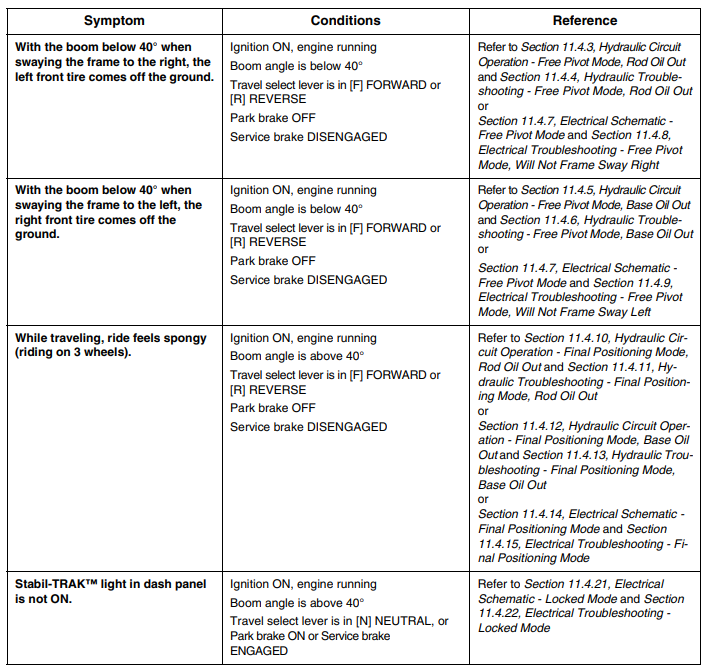
The function of the Stabil-TRAK™ system varies under different operating conditions. The basic modes include the FREE PIVOT MODE, FINAL POSITIONING MODE, and LOCKED MODE. The hydraulic and electrical operation and troubleshooting information for each of these modes will be described on the following pages.

For more manuals by JLG industries, visit ManualsLibraryy
JLG Sky Trak MMV Telehandler-FAQs
Are JLG and SkyTrak the same company?
No. JLG offers a full line of aerial work platforms (boom lifts, scissor lifts) and telehandlers. SkyTrak specializes only in telehandlers.
What’s the main difference between JLG and SkyTrak telehandlers?
JLG Telehandlers: Advanced tech, precision controls, higher-end models
SkyTrak Telehandlers: Cost-effective, simpler operation, reliable performance
Is SkyTrak owned by JLG?
No. SkyTrak was originally an independent brand before being acquired by Manitou, while JLG is part of Oshkosh Corporation.
How much hydraulic fluid does a SkyTrak 10054 hold?
The SkyTrak 10054 holds 60 gallons (225 liters) of hydraulic fluid.
What’s the maximum reach of a telehandler?
Vertical reach: 18–56 feet
Horizontal reach: 11–42 feet
(Varies by model; larger telehandlers may have outriggers for stability.)
What’s the lifting capacity of a standard telehandler?
Most telehandlers lift between 5,500–11,000 lbs (2.5–5 tons). High-capacity models can exceed 22,000 lbs (10 tons).
Can telehandlers operate on uneven terrain?
Yes! They feature 4WD, multiple steering modes, and rugged tires for rough terrain.
What training is needed to operate a JLG or SkyTrak telehandler?
MEWP (Mobile Elevated Work Platform) certification (required for JLG aerial lifts)
Telehandler-specific training (OSHA-compliant for safe operation)
How do you inspect a telehandler before use?
Perform a pre-operation walk-around check:
✔ Boom & hydraulic cylinders
✔ Tires/wheels
✔ Engine & fluid levels
✔ Safety sensors & controls
How do you read a telehandler load chart?
Bottom axis = Forward reach
Left axis = Lift height
Center values = Maximum load capacity at each position

