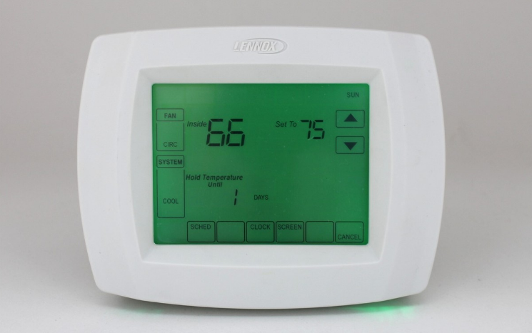
Lennox X4147 Touch Screen Thermostat
General
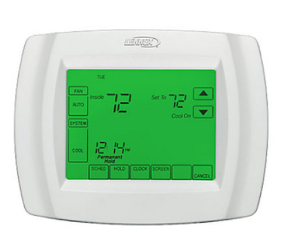
The Lennox ComfortSense™ 5000 Series L5732U programmable touch screen thermostat provides control for up to three stages of heating and two stages of cooling. The thermostat may be used to control either a conventional HVAC system, which includes an outdoor condensing unit and indoor furnace, or a heat pump unit and indoor air handler. The thermostat terminal block accommodates 24V power common from the furnace or air handler. Three AAA alkaline batteries are provided to be used as an alternate power source or as backup in case of an interruption of power.
Shipping and Packing List
Package 1 of 1 contains
- 1 − Assembled thermostat (includes wallplate and thermostat)
- 1− Bag assembly containing the following:
- 2 − Screws
- 2 − Wall anchors
- 3 − AAA alkaline batteries
- 1 − Installation instructions
- 1 − Owner’s guide
- 1 − Warranty certificate
Necessary Tools
- No. 2 Phillips screwdriver
- Standard pocket screwdriver
- Drill
- Drill bits (use 3/16″ for drywall and 7/32″ for plaster)
- Pencil
- Level
- Hammer
- Electrical tape
Thermostat Location
Install the thermostat about 5 feet (1.5m) above the floor in an area with good air circulation.
Do not install the thermostat where it may be affected by the following:
- Drafts or dead spots behind doors and in corners.
- Hot or cold air from ducts.
- Radiant heat from the sun or appliances.
- Concealed pipes or chimneys.
- Adjacent unconditioned areas (outside wall behind the thermostat).
Remove Existing Thermostat
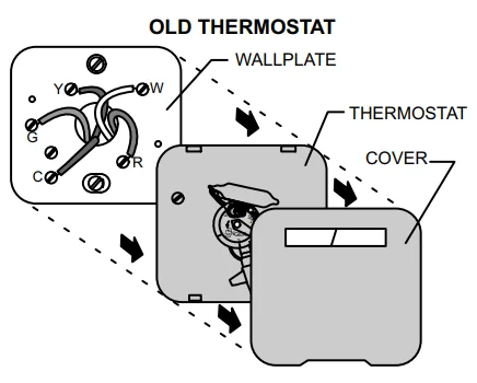
If this thermostat is being used to replace an existing thermostat, remove the old thermostat:
- Turn off the power at the heating and/or cooling system or fuse/circuit breaker panel.
- Remove the cover from the existing thermostat.
- Remove securing screws and remove the existing thermostat from the wall or wallplate. Disconnect and label the existing wires.
- Remove any remaining portion of the existing thermostat from the wall. Do not install the replacement thermostat faceplate on the existing wallplate. Though the wallplates may appear to be the same and the faceplate may fit on the existing wallplate, the terminal positions may vary in important ways. In addition, serial number and part number information is carried on the replacement wallplate.
Do not allow the thermostat wires to fall behind the drywall.
![]() WARNING
WARNING
This thermostat must be installed using the provided replacement wallplate.
Failure to do so will bypass thermostat control and activate continuous heating.
![]() WARNING
WARNING
MERCURY NOTICE
If the existing thermostat includes a mercury bulb, the thermostat must be disposed of properly.
Contact your local waste management authority for instructions regarding recycling and proper disposal of thermostats, which include mercury bulbs.
Thermostat Installation
The thermostat may be installed horizontally in a 4 in. X 2 in. (101.6 mm X 50.8 mm) wiring box or on the wall using the provided anchors.
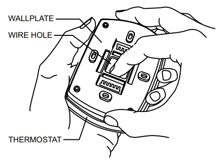
- Separate the wallplate from the thermostat as shown.

- Pass the labeled wires through the hole in the wallplate.
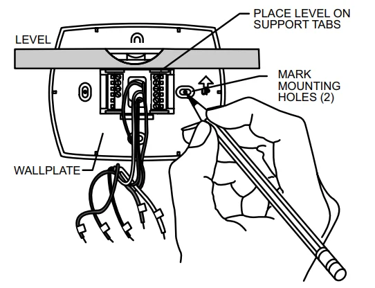
- Position the wallplate on the wall with the arrow pointing up. Level the wallplate (for appearance only) and use a pencil to mark the mounting holes.

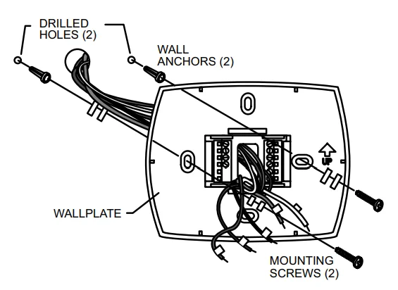
- If anchors are used, move the wallplate aside and drill two new holes (3/16″ for drywall; 7/32″ for plaster).
- Tap the provided wall anchors into the drilled holes until the back of the anchor head touches the wall surface.
- Position the wallplate over the anchors and pull the thermostat wires back through the wiring opening.
- Secure the wallplate using the provided screws.

![]() Note:
Note:
The thermostat heat function will not operate if the thermostat has been stored at, or is being used in, ambient temperatures at or above 90°F. Heat function will be enabled after the thermostat has been placed in ambient temperatures less than 90°F for about 30 minutes.
Wiring Connections
![]() WARNING
WARNING
Use a minimum 18-gauge wire for all thermostat connections.
![]() IMPORTANT
IMPORTANT
Do not connect the wires to this thermostat based on wire color. Improper wiring may cause damage to the HVAC system.
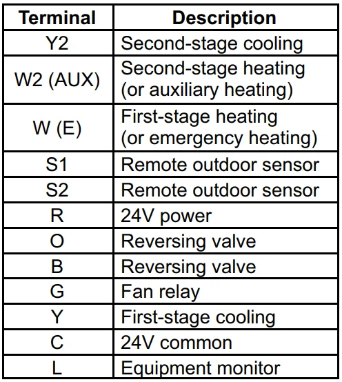
- Make wiring connections per the appropriate wiring diagram on pages 6 or 7. Refer to the table below for terminal designations.

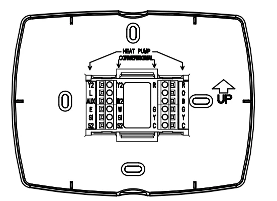
- Refer to inner terminal labels when using the thermostat with conventional systems (gas, oil, or electric heat plus air conditioning). Refer to outer terminal labels in heat pump applications. See the figure below.

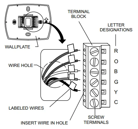
- Loosen the screws of the terminals that will be used. Insert appropriate wires in the terminal block under the loosened screws. Securely tighten each screw.

- Connect wires to the corresponding screw terminals per the appropriate diagram.
- Push excess wire back into the wall.
- Plug the hole with nonflammable insulation to prevent drafts from affecting the thermostat.
LED Indicator
An LED indicator is located in the upper right corner of the thermostat. It is only visible when lit. When an equipment monitor is connected to the thermostat L terminal, the LED lights when the monitor sends a check or failure message to the thermostat.
The LED requires the use of 24VAC common power. The indicator will not light when the thermostat is powered by the batteries alone or when 24VAC power is interrupted.
Outdoor Temperature Sensor
Install the optional outdoor temperature sensor (X4148) as outlined in the instructions provided with the sensor.
Field Wiring Diagrams
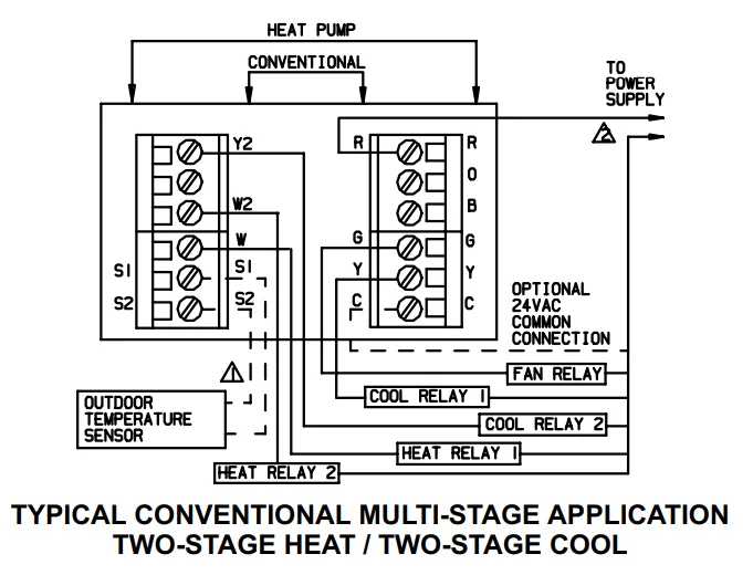
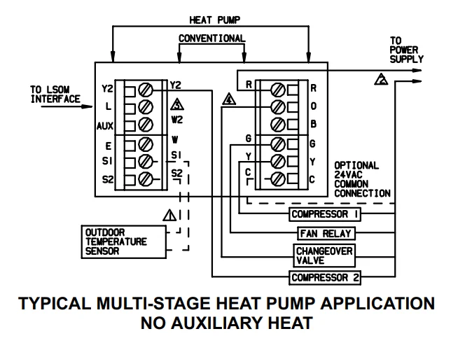
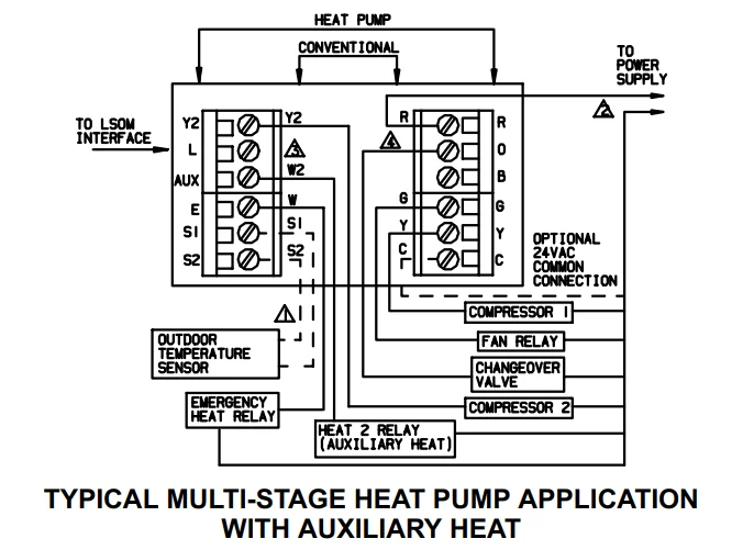
 OPTIONAL OUTDOOR TEMPERATURE SENSOR WIRES MUST HAVE A CABLE SEPARATE FROM THE THERMOSTAT CABLE
 POWER SUPPLY. PROVIDE DISCONNECT MEANS AND OVERLOAD PROTECTION AS REQUIRED
 MUST CONNECT THE 24VAC COMMON WHEN USING “L” THE TERMINAL IS SHOWN AS EQUIPMENT MONITOR.
 CONNECT CHANGEOVER VALVE TO “O” IF THE VALVE IS TO BE ENERGIZED DURING COOLING. CONNECT TO *B” IF ENERGIZED IN HEATING.
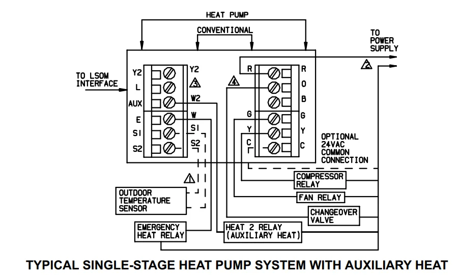
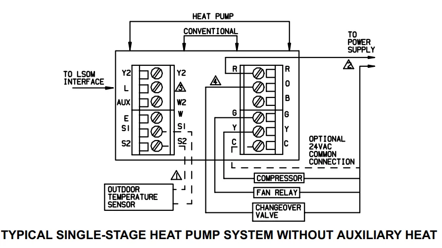
 OPTIONAL OUTDOOR TEMPERATURE SENSOR WIRES MUST HAVE A CABLE SEPARATE FROM THE THERMOSTAT CABLE
 POWER SUPPLY. PROVIDE DISCONNECT MEANS AND OVERLOAD PROTECTION AS REQUIRED
 MUST CONNECT THE 24VAC COMMON WHEN USING “L” THE TERMINAL IS SHOWN AS EQUIPMENT MONITOR.
 CONNECT CHANGEOVER VALVE TO “O” IF THE VALVE IS TO BE ENERGIZED DURING COOLING. CONNECT TO *B” IF ENERGIZED IN HEATING.
Install Batteries
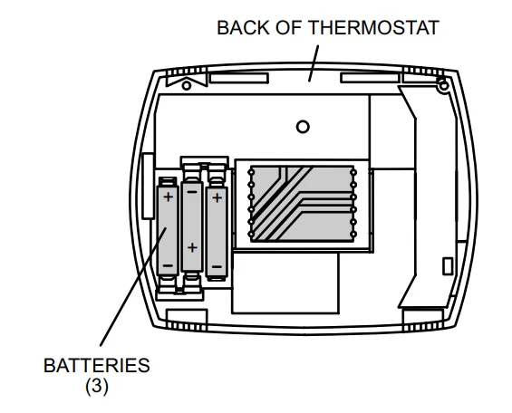
- Install three provided AAA alkaline batteries in the back of the thermostat as shown.

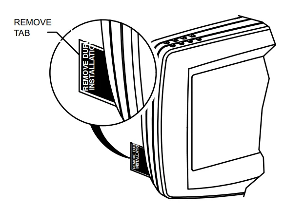
- Remove the tab from the lower right-hand corner of the thermostat to activate the real−time clock.

Attach Thermostat to Wallplate
NOTE − The thermostat may be programmed before it is secured to the wallplate.
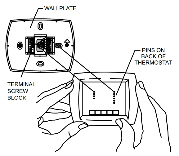
- Align the terminal blocks on the wallplate with the pins on the back of the thermostat.
- Push the thermostat straight onto the pins until it snaps into place.
- Turn on the power at the furnace or air handler or at the fuse, or circuit breaker.
Set Calendar and Clock
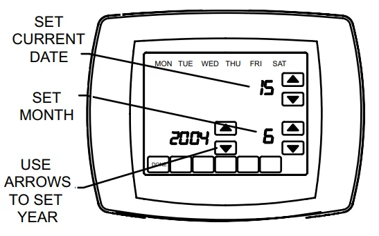
This thermostat is designed to automatically keep the current time and date in memory for up to ten years, under normal use, once the calendar has been set. When power is first applied to the thermostat, the display is ready to set the calendar.
- Use the arrow keys to set the year, month, and day.
- Press the DONE key.

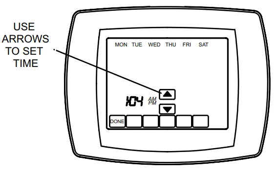
- Use the arrow keys to set the current time.
- Press the DONE key.

NOTE − Date and time may be adjusted after the initial setup using either the installer or user setup menu.
Advanced Heat Pump Features
The thermostat installer setup may be configured in several different ways to ensure the desired system operation.
Heat Pump Application
Dual Fuel (Fossil Fuel) Aux. Heat Outdoor Temperature Sensor and Thermostat Control Aux. Heat
(No external dual fuel kit)
Installer set−up as follows:
- Installer set−up number 0170 −− option 7, 11, or 12 −− heat pump.
- Installer set−up number 0200 −− option 1 −− back−up heat is fossil fuel.
- Installer set−up number 0210 −− option 0 −− no external fossil fuel kit.
- Installer set−up number 0340 −− not shown −− outdoor temperature sensor for control option chosen by default.
- Installer set−up number 0350 −− choose the appropriate balance point temperature.
Heating Mode Operation
Outdoor Temp. Above Balance Point
When the outdoor temperature is above the selected balance point, the compressor satisfies the heating demand.
However, if the room thermostat senses an indoor temperature drop of 2°F or more while the compressor is operating, the heat pump operation will stop, and the furnace will satisfy the remaining heating demand.
NOTE − The balance point setting is selected using Installer Set−Up Number 0350.
Heating Mode Operation
Outdoor Temp. Below Balance Point
When the outdoor temperature is below the selected balance point, only the furnace (fossil fuel) operates to satisfy the heating demand. The fan (G terminal) does not energize when the thermostat calls for heat.
Emergency Heat Operation
When the emergency heat mode of operation is selected by the thermostat, compressor operation is locked out. The first stage of heat becomes what is connected to the thermostat E terminal. The second stage of heat becomes what is connected to the Aux. Terminal. In cases where there is only one source of non−compressor heat, the E terminal must be jumped to the Aux. Terminal.
Heat Pump Application
Dual Fuel (Fossil Fuel) Aux. Heat Using External Dual Fuel Kit
Installer set−up as follows:
- Installer set−up number 0170 −− option 7, 11, or 12 −− heat pump.
- Installer set−up number 0200 −− option 1 −− back−up heat is fossil fuel.
- Installer set−up number 0210 −− option 1 −− external fossil fuel kit is controlling heat pump auxiliary heat.
- Installer set−up number 0340 −− option 0 or 1 −− outdoor temperature sensor not used or used for display only.
- Installer set−up number 0350 −− choose the appropriate balance point temperature.
Heat pump operation is determined by an external fossil fuel kit.
Heat Pump Application
Electric Auxiliary Heat with Outdoor Temperature Sensor
- Installer set−up number 0170 −− heat pump.
- Installer set−up number 0200 −− back−up heat is electric.
- Installer set−up number 0340 −− outdoor temperature sensor for control option chosen.
- Installer set−up number 0350 −− choose appropriate compressor lock−out temperature.
- Installer set−up number 0360 −− choose appropriate auxiliary lock-out temperature.
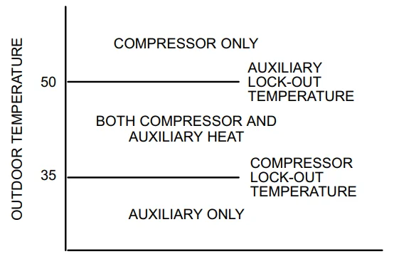
NOTE − There is a minimum 5°F deadband between the compressor and auxiliary heat lock−out temperatures.
Heating Mode Operation
When the outdoor temperature is below the compressor lock−out temperature (balance point), only the auxiliary heat operates.
When the outdoor temperature is above the auxiliary lock−out temperature (balance point), only the compressor operates.
When the outdoor temperature is between the two temperatures, both the compressor and auxiliary heat operate.
Emergency Heat Operation
When the thermostat is set for the emergency heat mode, the compressor and auxiliary lock−out features are turned off. Compressor operation is locked out. The first stage of heat becomes what is connected to the thermostat E terminal. The second stage of heat becomes what is connected to the Aux. tTerminal
Installer Set−Up
Use the following steps and the Installer Set−Up menu to match the thermostat to the HVAC system.
- Press and release the SYSTEM key.
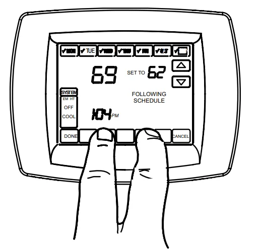
- Press and hold the two blank keys on either side of the center blank key for approximately five seconds.

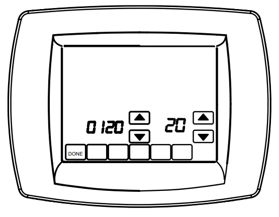
- Release the two keys when the thermostat display matches the display below.

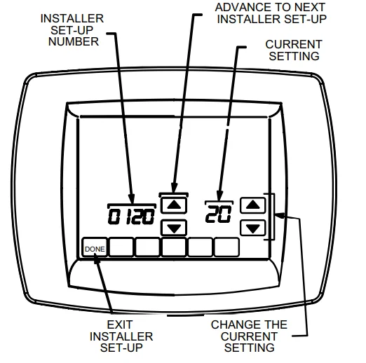
- Refer to the following figure to see how the thermostat keys are used to make selections from the setup menu.

- The installer set−up number is displayed on the left−hand side of the screen. The current installer’s setup number is displayed on the right−hand side of the screen. Use the up and down arrows on the right−hand side of the thermostat to select the proper setting for that particular setup number.
- After the proper selection has been made, use the up arrow in the center of the thermostat to advance to the next setup screen.
- Refer to the tables on pages 9 through 15 to make proper setup choices for your application.
- When all set−up selections have been made, press the DONE key to save your settings. The thermostat display will return to the main screen.
NOTE − Press and release the SYSTEM key, then press and hold the center blank key to access the user set−up screens. The user set−up options are limited to those features that would be used by the homeowner. Press the DONE key when finished.
System Test
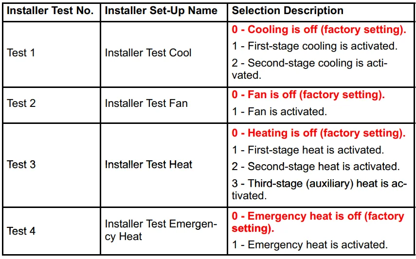
The system test function allows the installer to check the HVAC system after the thermostat set−up has been completed. The system test function is accessed through the installer setup menu.
- Press and release the SYSTEM key.
- Press and hold the two blank keys on either side of the center blank key for approximately five seconds, until the screen changes.
- Use the down arrow in the center of the thermostat to reach the installer test selections.
- The installer test number is displayed on the upper portion of the screen. Press the up or down arrow next to the word test on the screen to change the output to be tested.
- Refer to the following table to select the proper test options.
![]() CAUTION
CAUTION
While the system is in the test mode, the compressor’s minimum off time is bypassed.
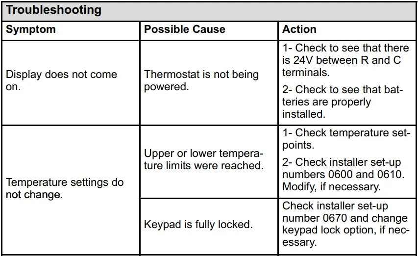
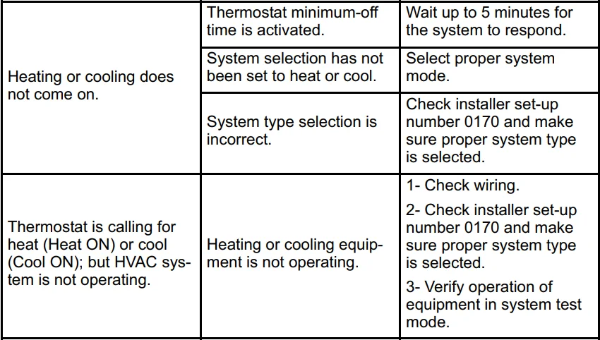
Troubleshooting

For more manuals by Lennox, visit ManualsLibraryy
Lennox X4147 Touch Screen Thermostat- FAQs
How do I use the Lennox X4147 thermostat?
You can adjust temperature, fan, and system settings directly on the touchscreen. Use the menu to schedule heating/cooling, set programs, or access advanced options.
Can I control my Lennox thermostat from my phone?
Yes, using the iComfort® Smart Thermostat app, you can control temperature, set schedules, receive alerts, and monitor your HVAC system remotely.
Why isn’t my touch screen thermostat responding?
This may happen due to a power issue, dead batteries, or dirt on the screen. Try a soft reset by briefly cutting power, check for firmware updates, and ensure the HVAC system is powered properly.
How do I reset my Lennox thermostat?
Go to Menu > Settings > Reboot, then confirm by pressing Yes. For a manual reset, turn off power to the unit for 30 seconds, then restore it.
How do I unlock my Lennox touchscreen thermostat?
Touch and hold the lock icon on the screen for 5–6 seconds until it unlocks.
Does the Lennox thermostat have a battery?
Yes, it uses backup batteries to retain settings and maintain operation during power outages.
How do I connect my Lennox thermostat to Wi-Fi?
Open the iComfort app and follow the on-screen instructions to link your thermostat to your home Wi-Fi network for remote control and smart features.
Can a smart thermostat work without Wi-Fi?
Yes, it can control heating and cooling locally, but advanced features like remote access, notifications, and automated energy optimization won’t work.
What is the “3-minute rule” for air conditioners?
After turning off your AC, wait at least 3 minutes before turning it back on. This prevents damage by allowing refrigerant pressure to equalize.
How do I check if my thermostat is working?
Ensure the system responds to temperature changes. If the HVAC doesn’t turn on/off as expected, the thermostat may need troubleshooting or resetting.

