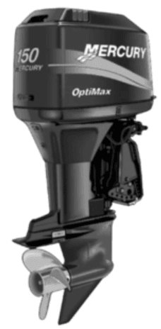
Mercury OptiMax 150 Outboard Motor Engine
GENERAL INFORMATION
Propellers are designated by the diameter, pitch, number of blades, and material. The diameter and pitch are stamped (cast) into the side or the end of the propeller hub. The first number represents the diameter of the propeller, and the second number represents the pitch. For example, 14×19 represents a propeller with a 14-inch diameter and 19 inches of pitch.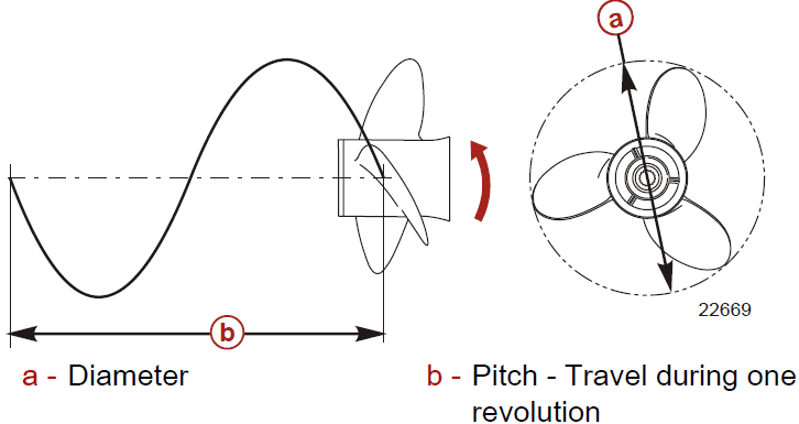
The following are some propeller basics that will help you determine the correct propeller for your boating application.
Diameter
The diameter is the distance across the imaginary circle that is made when the propeller rotates. The correct diameter for each propeller has been predetermined for the design of your outboard. However, when more than one diameter is available for the same pitch, use a larger diameter for heavy boat applications and a smaller diameter for lighter applications.
Pitch
The pitch is the theoretical distance, in inches, that a propeller travels forward during one revolution. Pitch can be thought of as similar to gears in a car. The lower the gear, the faster the car will accelerate, but with a lower overall top speed. Likewise, a lower pitch propeller will accelerate quickly, but top‑end speed will be reduced. The higher the propeller pitch, the faster the boat will usually go, though typically with slower acceleration.
Determining the Correct Pitch Size
First, check the full throttle RPM under normal load conditions. If the full throttle RPM is within the recommended range, select a replacement or upgrade propeller with the same pitch as the current propeller.
- Adding 1 inch of pitch will reduce the full throttle RPM by 150 to 200
- Subtracting 1 inch of pitch will increase full throttle RPM by 150 to 200
- Upgrading from a 3‑blade propeller to a 4‑blade propeller will generally decrease full throttle RPM by 50 to 100
IMPORTANT: Avoid damage to the engine. Never use a propeller that allows the engine to exceed the recommended full throttle RPM range when under normal full throttle operation.
PROPELLER MATERIAL
Most propellers manufactured by Mercury Marine are made from either aluminum or stainless steel. Aluminum is suitable for general-purpose use and is standard equipment on many new boats. Stainless steel is over five times more durable than aluminum and typically provides performance gains in acceleration and top-end speed due to design efficiencies. Stainless steel propellers also come in a larger variety of sizes and styles that allow you to dial in the ultimate performance for your boat.
3 BLADE VS. 4 BLADE
Available in many sizes of both aluminum and stainless, 3 and 4‑blade propellers have unique performance characteristics. In general, 3‑blade propellers offer good all-around performance and higher top speed than 4‑blade propellers. However, 4‑blade propellers are usually faster to plane and more efficient at cruising speeds, but lack the top-end speed of a 3‑blade propeller.
Outboard Remote Control Model
The remote control connected to your outboard must be equipped with a start-in-neutral-only protection device. This prevents the engine from starting when the shift is actuated in any position other than neutral.
Remote Steering Notice
The steering link rod that connects the steering cable to the engine must be fastened utilizing self‑locking nuts. These self‑locking nuts must never be replaced with common nuts (non‑locking) as they will work loose and vibrate off, freeing the link rod to disengage.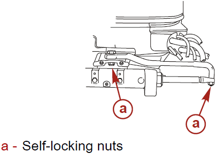
WARNING
Improper fasteners or improper installation procedures can result in loosening or disengagement of the steering link rod. This can cause a sudden, unexpected loss of boat control, resulting in serious injury or death due to occupants being thrown within or out of the boat. Always use required components and follow instructions and torque procedures.
Lanyard Stop Switch
The purpose of a lanyard stop switch is to turn off the engine when the operator moves far enough away from the operator’s position (as in accidental ejection from the operator’s position) to activate the switch. Tiller handle outboards and some remote control units are equipped with a lanyard stop switch. A lanyard stop switch can be installed as an accessory, generally on the dashboard or side adjacent to the operator’s position.
The lanyard is a cord usually 122 ‑ 152 cm (4 ‑ 5 feet) in length when stretched out, with an element on one end made to be inserted into the switch and a snap on the other end for attaching to the operator. The lanyard is coiled to make its at‑rest condition as short as possible to minimize the likelihood of lanyard entanglement with nearby objects. Its stretched‑out length is made to minimize the likelihood of accidental activation should the operator choose to move around in an area close to the normal operator’s position. If it is desired to have a shorter lanyard, wrap the lanyard around the operator’s wrist or leg, or tie a knot in the lanyard.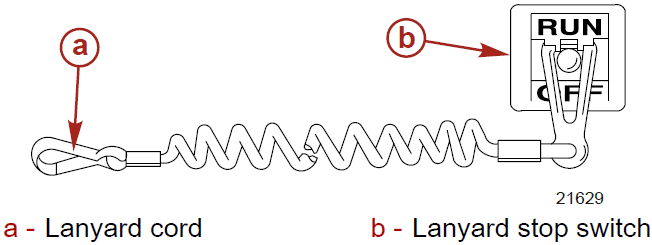
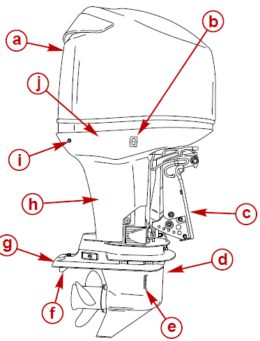
Component Identification
- Top cowl
- Auxiliary tilt switch
- Transom brackets
- Gearcase
- Cooling water intake holes
- Trim tab
- Anti‑ventilation plate
- Driveshaft housing
- Water pump indicator hole
- Bottom cowl
TRANSPORTING
Trailering Boat/Outboard
Trailer your boat with the outboard tilted down in a vertical operating position.
If additional ground clearance is required, the outboard should be tilted up using an accessory outboard support device. Refer to your local dealer for recommendations. Additional clearance may be required for railroad crossings, driveways, and trailer bouncing.
IMPORTANT: Do not rely on the power trim/tilt system or tilt support lever to maintain proper ground clearance for trailering. The outboard tilt support lever is not intended to support the outboard for trailering.
Shift the outboard to forward gear. This prevents the propeller from spinning freely.
FUEL AND OIL
The fuel system components on your Mercury Marine engine will withstand up to 10% alcohol content in the gasoline. We do not know what percentage of your boat’s fuel system will withstand.
Contact your boat manufacturer for specific recommendations on the boat’s fuel system components (fuel tanks, fuel lines, and fittings). Be aware that gasolines containing alcohol may cause increased:
- Corrosion of metal parts
- Deterioration of rubber or plastic parts
- Fuel permeation through rubber fuel lines
- Starting and operating difficulties
WARNING
Fuel leakage is a fire or explosion hazard, which can cause serious injury or death. Periodically inspect the fuel system components for leaks, softening, hardening, swelling, or corrosion, particularly after storage. Any sign of leakage or deterioration requires replacement before further engine operation.
Because of the possible adverse effects of alcohol in gasoline, it is recommended that only alcohol‑free gasoline be used where possible. If only fuel containing alcohol is available, or if the presence of alcohol is unknown, increased inspection frequency for leaks and abnormalities is required.
IMPORTANT: When operating a Mercury Marine engine on gasoline containing alcohol, storage of gasoline in the fuel tank for long periods should be avoided. Long periods of storage, common to boats, create unique problems. In cars, alcohol‑blend fuels normally are consumed before they can absorb enough moisture to cause trouble, but boats often sit idle long enough for phase separation to take place. In addition, internal corrosion may take place during storage if alcohol has washed protective oil films from internal components.
Fuel Requirements
Do not use pre‑mixed gas and oil in this engine. The engine automatically receives extra oil during engine break‑in. Use a fresh supply of the recommended gasoline during engine break‑in and after engine break‑in.
Fuel Additives
To minimize carbon deposit buildup in the engine, it is recommended to add Mercury or Quicksilver Quickleen Engine Treatment additive to the engine’s fuel at each tank fill throughout the boating season. Use the additive as directed on the container.
Avoiding Fuel Flow Restriction
IMPORTANT: Adding components to the fuel supply system (filters, valves, fittings, etc.) may restrict the fuel flow. This may cause engine stalling at low speed, and/or a lean fuel condition at high RPM that could cause engine damage.
Filling the Fuel Tank
WARNING
Avoid serious injury or death from a gasoline fire or explosion. Use caution when filling fuel tanks. Always stop the engine and do not smoke or allow open flames or sparks in the area while filling fuel tanks.
Fill fuel tanks outdoors away from heat, sparks, and open flames.
Remove portable fuel tanks from the boat to refill them.
Always stop the engine before refilling the tanks.
Do not completely fill the fuel tanks. Leave approximately 10% of the tank volume unfilled. Fuel will expand in volume as its temperature rises and can leak under pressure if the tank is completely filled.
FEATURES AND CONTROLS
WARNING
Trimming the outboard beyond a neutral steering condition may result in a pull on the steering wheel or tiller handle and loss of boat control. Maintain control of the boat if trimming beyond a neutral steering condition.
Consider the following lists carefully.
- Trimming In or Down Can:
- Lower the bow.
- Result in quicker planning off, especially with a heavy load or a heavy stern boat.
- Generally, improve the ride in choppy water.
- Increase steering torque or pull to the right (with the normal right-hand rotation propeller).
- In excess can lower the bow of some boats to a point where they begin to plow with their bow in the water while on plane. This can result in an unexpected turn in either direction (called bow steering or over‑steering) if any turn is attempted, or if a significant wave is encountered. WARNING: Operating the boat at high speeds with the outboard trimmed too far under can create excessive bow steer, resulting in the operator losing control of the boat. Install the trim limit pin in a position that prevents excessive trim under and pilot the boat in a safe manner.
- In rare circumstances, the owner may decide to limit the trim in. This can be accomplished by purchasing a stainless steel tilt pin from your dealer and inserting it in whatever adjustment hole in the transom brackets is desired. The non‑stainless steel shipping bolt should not be used in this application.
- Trimming Out or Up can:
- Lift the bow higher out of the water.
- Generally, increase top speed.
- Increase clearance over submerged objects or a shallow bottom.
- Increase steering torque or pull to the left at a normal installation height (with the normal right-hand rotation propeller).
- In excess can cause boat porpoising (bouncing) or propeller ventilation.
- Cause engine overheating if any cooling water intake holes are above the water line.
MAINTENANCE
INSTALLATION
Position the cover onto the three mounting pins. Insert the tabs into the slots in the side panel and push the cover down onto the mounting pins.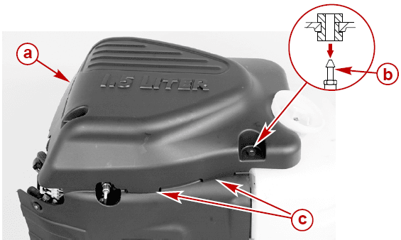
- Flywheel cover
- Mounting pins
- Tabs
Position the side panel onto the three mounting pins. Insert the tabs on the flywheel cover into the upper slots and push the side panel onto the mounting pins.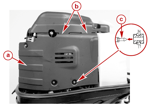
- Side panel
- Upper slots
- Mounting pins
Fuel System
WARNING
Fuel is flammable and explosive. Ensure the key switch is off and the lanyard is positioned so that the engine cannot start. Do not smoke or allow sources of spark or open flame in the area while servicing. Keep the work area well ventilated and avoid prolonged exposure to vapors. Always check for leaks before attempting to start the engine, and wipe up any spilled fuel immediately.
Corrosion Control Anode
Your outboard has corrosion control anodes at different locations. An anode helps protect the outboard against galvanic corrosion by sacrificing its metal to be slowly corroded instead of the outboard’s metals.
Battery Inspection
The battery should be inspected at periodic intervals to ensure proper engine starting capability.
IMPORTANT: Read the safety and maintenance instructions that accompany your battery.
- Turn off the engine before servicing the battery.
- Add water as necessary to keep the battery full.
- Make sure the battery is secure against movement.
- Battery cable terminals should be clean, tight, and correctly installed. Positive to positive and negative to negative.
- Make sure the battery is equipped with a non‑conductive shield to prevent accidental shorting of battery terminals.
Gearcase Lubrication
When adding or changing gearcase lubricant, visually check for the presence of water in the lubricant. If water is present, it may have settled to the bottom and will drain out prior to the lubricant, or it may be mixed with the lubricant, giving it a milky colored appearance. If water is noticed, have the gearcase checked by your dealer. Water in the lubricant may result in premature bearing failure or, in freezing temperatures, will turn to ice and damage the gearcase.
Examine the drained gearcase lubricant for metal particles. A small amount of metal particles indicates normal gear wear. An excessive amount of metal filings or larger particles (chips) may indicate abnormal gear wear and should be checked by an authorized dealer.
DRAINING GEARCASE
- Place the outboard in a vertical operating position.
- Place a drain pan below the outboard.
- Remove vent plugs and fill/drain plug, and drain lubricant.
STORAGE
Storage Preparation
The major consideration in preparing your outboard for storage is to protect it from rust, corrosion, and damage caused by freezing of trapped water.
The following storage procedures should be followed to prepare your outboard for out-of-season storage or prolonged storage (two months or longer).
NOTICE
Failure to provide sufficient cooling water will damage the water pump and cause the engine to overheat. Provide a sufficient supply of water at the water inlets during operation.
Fuel System
IMPORTANT: Gasoline containing alcohol (ethanol or methanol) can cause the formation of acid during storage and can damage the fuel system. If the gasoline being used contains alcohol, it is advisable to drain as much of the remaining gasoline as possible from the fuel tank, remote fuel line, and engine fuel system.
The most effective method of storage preparation is to add the recommended amount of Mercury Precision Fuel Stabilizer and Mercury Precision Quickleen products as described on the containers, to the fuel tank before the last operation of the boat.
Adding a fuel stabilizer will help prevent the formation of varnish and gum in the gasoline. The Mercury Precision Quickleen product will help clean and lubricate the fuel injectors.
- Portable Fuel Tank ‑ Pour the required amount of gasoline stabilizer and Quickleen (follow instructions on containers) into the fuel tank. Tip the fuel tank back and forth to mix stabilizer and Quickleen with the fuel.
- Permanently Installed Fuel Tank ‑ Pour the required amount of gasoline stabilizer and Quickleen (follow instructions on containers) into a separate container and mix with approximately 1 liter (1 quart) of gasoline. Pour this mixture into the fuel tank.
- Pull the drain hose off the right side fitting. Hold the open end of the hose over a container.
- Loosen drain screw and drain the fuel filter chamber.
- Retighten the drain screw and reattach the hose.
- Pull the drain hose off the left side fitting. Hold the open end of the hose over a container.
- Loosen the drain screw and drain the float chamber.
- Retighten the drain screw and reattach the hose.
- Premix the following in a container: 8 cc (0.27 oz.) or 2 teaspoons of Mercury Precision Quickleen lubricant. 8 cc (0.27 oz.) or 2 teaspoons of Mercury Precision Fuel Stabilizer.
- Remove the fuel filter. See Maintenance – Fuel System for procedure.
- Pour this mixture into the fuel filter opening. Reinstall the fuel filter.
- Prime the fuel system. See Operation – Starting The Engine.
- Place the outboard in water or use the flush hose or flushing device for circulating cooling water. Start the engine and run at idle speed for five minutes to allow the treated fuel to fill the fuel system.
Battery Storage
- Follow the battery manufacturer’s instructions for storage and recharging.
- Remove the battery from the boat and check the water level. Recharge if necessary.
- Store the battery in a cool, dry place.
- Periodically check the water level and recharge the battery during storage.
TROUBLESHOOTING
Starter Motor Will Not Crank the Engine
POSSIBLE CAUSES
- Blown 20 amp fuse in the starting circuit. Refer to Maintenance.
- The outboard is not shifted to the neutral position.
- Weak battery or battery connections are loose or corroded.
- Ignition key switch failure.
- The wiring or electrical connection is faulty.
- Starter motor solenoid or slave solenoid failure.
Engine Will Not Start
POSSIBLE CAUSES
- The lanyard stop switch is not in the “RUN” position.
- Battery not fully charged.
- Incorrect starting procedure. Refer to the Operation section.
- Old or contaminated fuel.
- Fuel is not reaching the engine.
- The fuel tank is empty.
- Fuel tank vent not open or restricted.
- The fuel line is disconnected or kinked.
- The primer bulb was not squeezed.
- The primer bulb check valve is faulty.
- The fuel filter is obstructed. Refer to the Maintenance section.
- Fuel pump failure.
- The fuel tank filter was obstructed.
- Open 20 20-amp fuse. Check fuses, refer to the Maintenance section.
- The threaded connection of the air hose is loose.
- Ignition system component failure.
- Spark plugs are fouled or defective. Refer to the Maintenance section.
For more Manuals by Mercury, visit ManualsLibraryy
Mercury OptiMax 150 Outboard Motor Engine-FAQs
Is the Mercury OptiMax 150 a reliable engine?
Yes, the Mercury OptiMax 150 is widely considered one of the best Mercury engines. It features a proven 2.5L, 60° V6 powerhead known for durability and strong performance.
How much fuel does a Mercury 150 outboard use?
At full throttle, the Mercury 150 burns around 55 liters per hour, giving you roughly 0.67 nautical miles per liter—a solid fuel efficiency for a high-output engine.
What is the oil-to-fuel ratio for a Mercury 150 2-stroke?
The recommended oil ratio is 100:1, which means you should mix 50 ml of oil per 5 liters of fuel.
How often should I change the oil in a Mercury 150 FourStroke?
Oil and oil filters should be changed every 100 hours of use or once a year, whichever comes first.
Can I run my outboard motor without water?
No, never run your outboard engine without water or a water flushing device attached. Doing so can damage the impeller, which needs water for cooling.
What type of fuel should I use in my Mercury outboard?
Use unleaded fuel with up to 10% ethanol (E10). Do not use fuels with higher ethanol content like E15 or E85.
How long can an outboard engine run before issues start?
Most outboard engines, including the Mercury 150, can run for around 1,500 hours with regular maintenance. Well-cared-for engines may last longer.
How many hours does a Mercury OptiMax engine typically last?
With proper use and care, an OptiMax engine can last between 2,000 to 3,000 hours.

