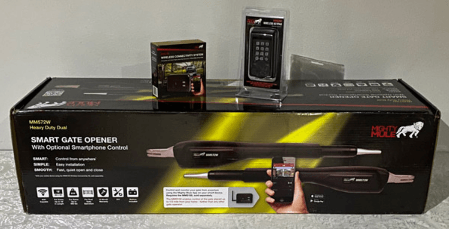
Mighty Mule TS571W Single Swing Smart Gate Opener
Important Safety Information
Because automatic gate operators produce high levels of force, consumers need to know the potential hazards associated with improperly designed, installed and maintained automated gate operator systems. Keep in mind that the gate operator is just one component of the total gate operating system. Each component must work in unison to provide the end user with convenience, security, and safety. This manual contains various safety precautions and warnings for the installer and end user. Because there are many possible applications of the gate operator, the safety precautions and warnings contained in this manual cannot be completely exhaustive in nature. It does, however, provide an overview of the safe design, installation, and use of this product. CAREFULLY READ AND FOLLOW ALL SAFETY PRECAUTIONS, WARNINGS, AND INSTALLATION INSTRUCTIONS TO ENSURE THE SAFE SYSTEM DESIGN, INSTALLATION, AND USE OF THIS PRODUCT.
MANUALLY OPENING AND CLOSING GATE
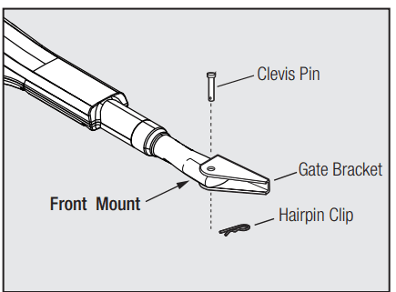
Disconnecting the Operator
- Turn control box power switch OFF.
- Remove the hairpin clip and clevis pin.
- Remove the operator’s front mount from the gate bracket.
The gate can be opened and closed manually when the operator is disconnected.
- READ AND FOLLOW ALL INSTRUCTIONS.
- Never let children operate or play with gate controls. Keep the remote control away from children.
- Always keep people and objects away from the gate. NO ONE SHOULD CROSS THE PATH OF THE MOVING GATE.
- Test the gate operator monthly. The gate MUST reverse on contact with a rigid object or stop when an object activates the non-contact sensors. After adjusting the force or the limit of travel, retest the gate operator. Failure to adjust and retest the gate operator properly can increase the risk of injury or death.
- Use the manual/emergency release only when the gate is not moving.
- KEEP GATES PROPERLY MAINTAINED. Read the user’s manual. Have a qualified service person make repairs to gate hardware.
- The entrance is for vehicles only. Pedestrians must use separate entrances.
- The gate must be installed in a location that provides adequate clearance between it and adjacent structures when opening and closing to reduce the risk of entrapment. Swinging gates must not open into public access areas.
- SAVE THESE INSTRUCTIONS.
Before Installation
- Verify this operator is proper for the type and size of the gate, frequency of use and class of the gate system.
- Make sure the gate has been properly installed and swings freely in both directions. Repair or replace all worn or damaged gate hardware prior to installation. A freely moving gate will require less force to operate and will enhance the performance of the entrapment protection devices used with the system (see page 13).
- Review the operation of the system to become familiar with its safety features. Understand how to disconnect the operator for manual gate operation (see page 4).
- The gate and operator installation must comply with any applicable local codes.
- This gate operator is intended for vehicular gates only. A separate entrance or gate must be installed for pedestrian use (see page 9).
- Always keep people and objects away from the gate and its area of travel. No one should cross the path of a moving gate.
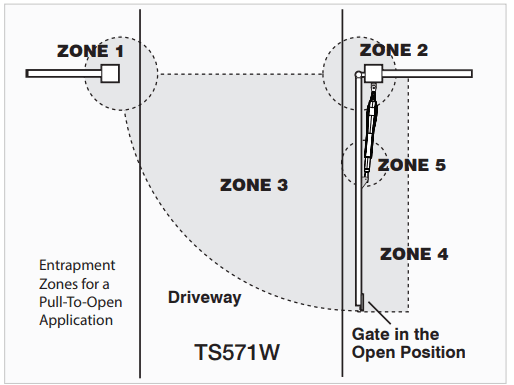
- Identify all of the entrapment zones for the type of installation. An entrapment zone is an area around the automatic gate system where a person or object could be caught that increases the risk of injury. Entrapment zones should be eliminated, guarded, or protected.
- When designing a system that will be entered from a highway or main thoroughfare, make sure the gate system is placed far enough from the road to prevent traffic congestion.

During Installation
- Install the gate operator on the inside of the property and fence line. DO NOT install an operator on the outside of the gate where the public has access to it.
- Be careful with moving parts and avoid close proximity to areas where fingers or hands could be pinched.
- Devices such as contact sensors (sensing edges) and noncontact sensors (photo beams) provide
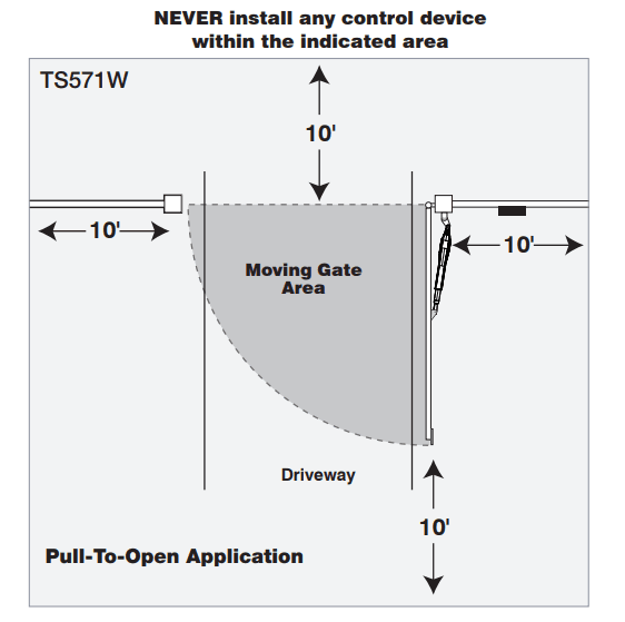
additional protection against vehicular damage. - If push buttons or key switches are installed, they should be within sight of the gate, located at least 10 feet from any moving part of the gate (see diagram below). Never install any control device where a user will be tempted to reach through the gate to activate the gate operator.
- Secure outdoor or easily accessed gate operator controls to prohibit unauthorized use of the gate.

Before You Begin
Determine the Charging Option for the Battery: Transformer OR Solar
IMPORTANT:
- The TS571 is designed for a 12-volt auto or marine battery.
- The transformer is designed for indoor use. If the transformer can be plugged only into an outside electrical outlet, a weatherproof cover/housing (available at local electrical supply stores) must be used.
- If your gate is more than 1000 ft. from an AC power source, you will need to use at least 10-watt solar charging power to charge the battery [FM123]. Refer to the Solar Panel and Gate Activity chart below.
- All low voltage wire used with the Mighty Mule gate operator must be 16 gauge dual conductor, stranded, direct burial wire [RB509]. Do not run more than 1000 ft. of wire.
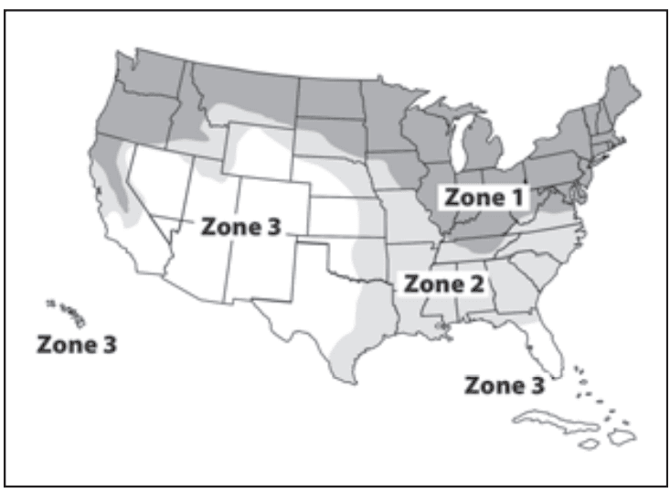
SOLAR PANEL AND GATE ACTIVITY CHART
The table and map illustrate the maximum number of gate cycles to expect per day in a particular area when using from 10 to 30 watts of solar charging power before the battery depletes to a state where the unit will not function. The figures shown are for winter (minimum sunlight). Accessories connected to
your system will draw additional power from the battery. A deep-cycle marine battery is recommended for solar and/or high-traffic applications.
NOTE: Up to 250 feet of dual conductor, 16 gauge, multi-stranded wire may be used to allow installation of solar panels in direct sunlight. 10 Watt Solar Panel [FM123]
| Single Gate Winter Ratings | Zone 1 | Zone 2 | Zone 3 |
| 12 v single gate (10 watts) solar charger | 8 | 16 | 26 |
| 12 v single gate (20 watts) solar charger | 14 | 28 | 38 |
| 12 v single gate (30 watts) solar charger | 20 | 44 | 54 |
IMPORTANT: CHECK FOR PROPER GATE INSTALLATION
- The gate must be plumb, level, and swing freely on its hinges.
- The gate must move throughout its arc without binding or dragging on the ground.
- Wheels must NOT be attached to the gate.
- Gates over 250 lb. should have ball-bearing hinges with grease fittings.
- Post must be secured in the ground with concrete (minimizes twist/flex when the operator is activated).
- Make sure there is a stable area for mounting the gate bracket (this may require the addition of a horizontal or vertical cross member).
- We recommend you position the operator near the center line of a gate to keep the gate from twisting and flexing, and to avoid back-splash from rain.
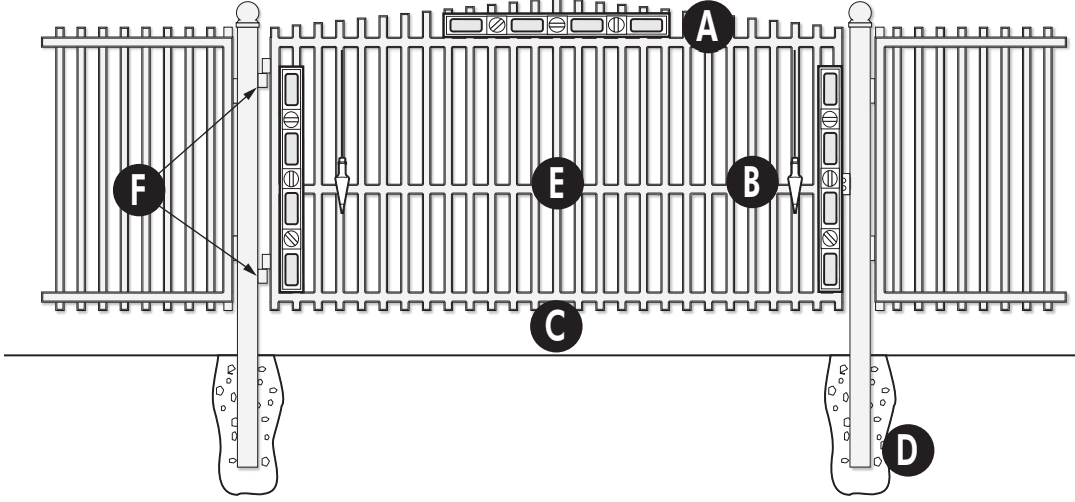
- A – Level
- B – Plumb
- C – Free Swinging
- D – Secured Posts in Concrete
- E – Center line Mounting
- F – Good Working Hinges (ball bearing hinges are recommended on gates over 250 pounds)
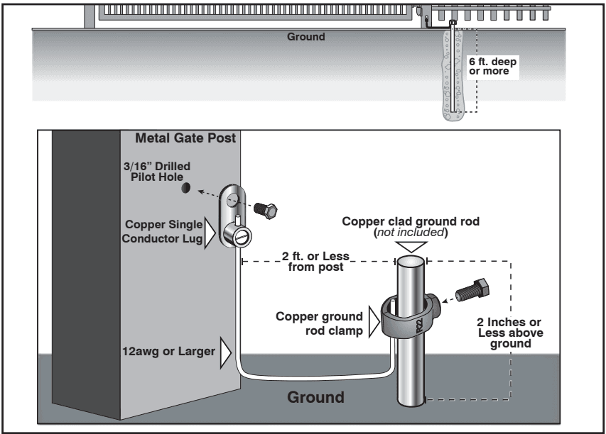
Gate Grounding
- For reference only.
Cooper Clad Ground Rod (not included)
Use an 8-foot, 5/8-inch ground rod, positioned two feet or less from the post and 2 inches or less above the ground. Available at local home centers or hardware stores.
NOTE: No grounding system protects against lightning strikes. If installed correctly, a grounding system will help minimize damage to your gate operator.
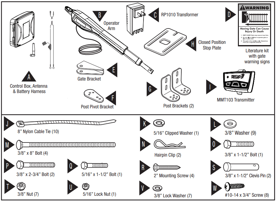
ITEMS INCLUDED FOR GATE OPERATOR INSTALLATION (TS571W)
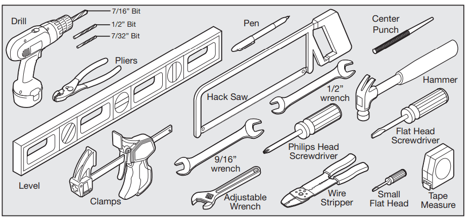
TOOLS NEEDED
ITEMS NOT INCLUDED
- 12 Volt Auto or Marine Battery.
- Needed is 16 gauge low voltage direct burial wire to run from the transformer to the control box; length depends upon the distance between the transformer power supply and the control box. See Transformer or Solar panel wiring Installation on page 33, and the accessory catalog.
- PVC conduit.
- If you have thin-walled tube or panel gates, see Reinforcing Gates for the Gate Brackets, next page.
- Depending on the type of gate, a horizontal cross member or mounting plate may be needed to mount the front of the operator and gate bracket to the gate. See the Reinforcing Gates for the Gate
Brackets examples, next page. - Surge protection for transformer.
- Some types of installations require U-bolts.
- Additional washers or a metal plate may be needed for wooden post.
- Weatherproof cover for outdoor outlet and transformer.
- If the post is larger than 6”, bolts longer than 8” are needed.
- 12 Volt outdoor auto or marine battery
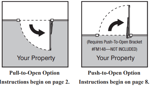
CHECK THE DIRECTION OF THE GATE SWING
Mechanical Installation
ASSESSING THE GATE FOR INSTALLATION
Your gate operator can be mounted to a variety of gate types. This section shows some of the most common, along with the reinforcement methods recommended prior to or while mounting your gate operator.
Reinforcing Gates for the Gate Brackets
We recommend using a muffler clamp, wood, or metal, to reinforce thin-walled tube gates, or wood to reinforce panel gates as shown. These reinforcement methods will prevent damage to the opener and gate. Additional hardware may be needed depending on the installation. Additional hardware is necessary but not included.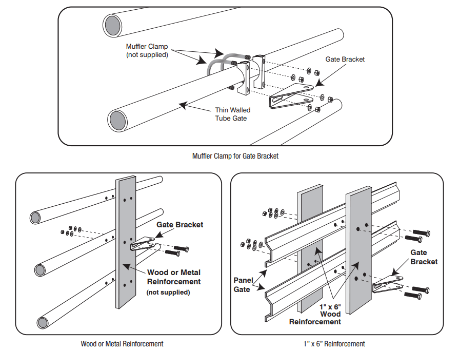
PULL-TO-OPEN OPERATOR MOUNTING (MOST COMMON)
Step 1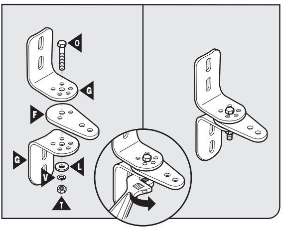
- Assemble the gate post bracket sub-assembly as displayed.
Step 2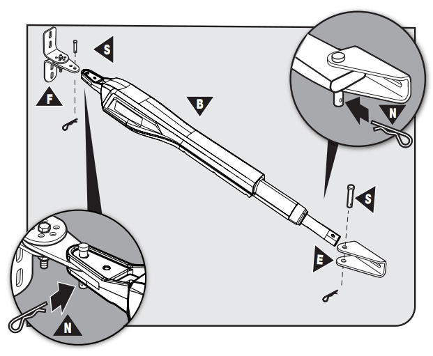
- Attach the gate post bracket subassembly and gate bracket to the operator as shown.
Step 3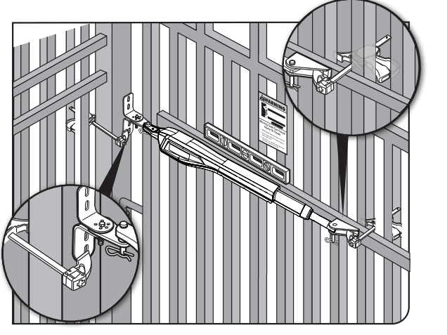
- With the gate in the OPEN position, use clamps to secure the operator to the gate post and center cross member of the gate.
- Ensure that the operator is level.
- With the operator’s arm temporarily secured to the gate, check to ensure there is at least 2 inches of clearance between the operator’s arm and gate. (See illustration in Step 4 below).
Step 4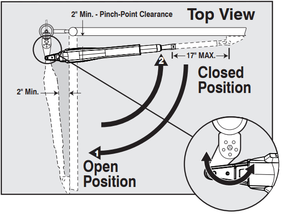
- Disconnect the operator arm from the gate bracket.
- While supporting the operator, swing the gate and operator to the closed position.
- Check for recommended clearances and binding as shown.
- Ensure that the necessary arm stroke does not exceed 20 inches.
- Make adjustments to the mounting brackets to achieve the recommended clearances.
TIP: Turning the pivot bracket over gives more hole alignment options for the gate post pivot bracket assembly.
Step 5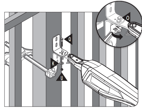
- Open the gate and reattach the operator to the gate bracket.
- Ensure that the operator’s arm is level and the brackets are securely clamped.
- Secure the post-pivot bracket in place by installing the hardware shown. Tighten both bolts (O and Q).
Step 6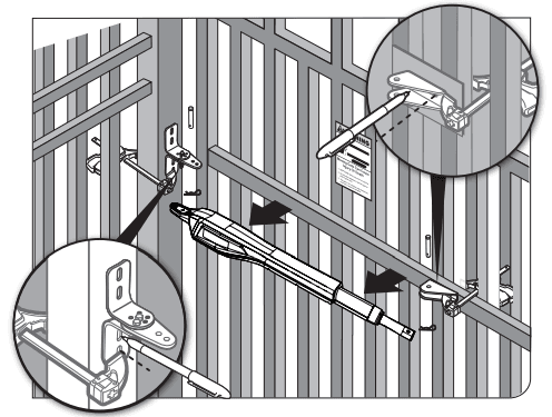
- Using a permanent marker, mark the center of the mounting locations for the gate post bracket subassembly.
- Remove the operator arm from the gate post and gate brackets.
- Mark the center of the mounting locations for the gate bracket.
Step 7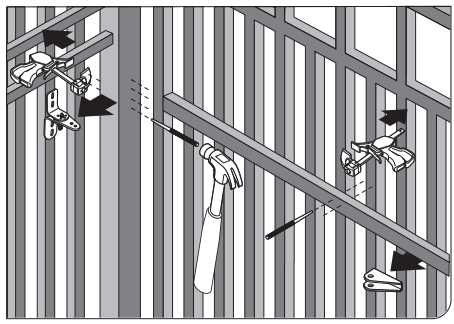
- Remove the gate post and gate brackets.
- Use a hammer and center punch to mark the center of the mounting locations.
Step 8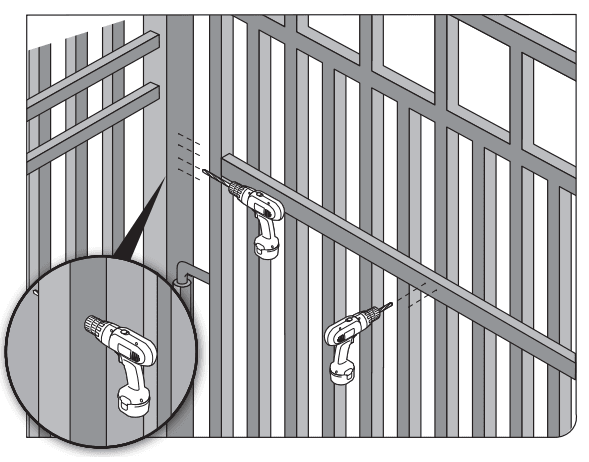
- Using a drill and 7/16” drill bit, drill the necessary holes to mount the gate post and gate brackets.
Note: Some installations may require additional reinforcement to be installed on the gate. See page 16.
Step 9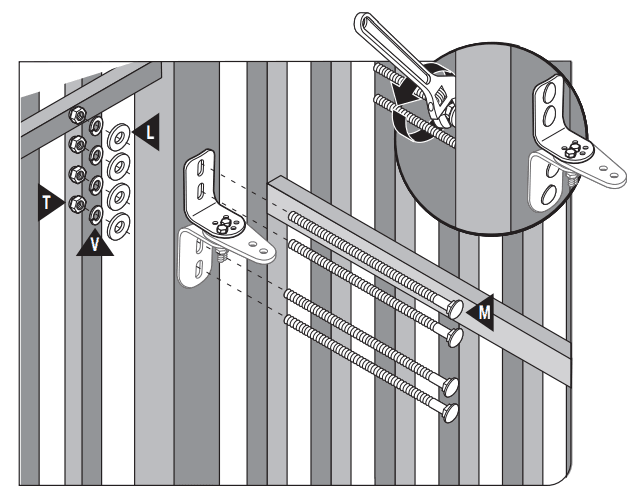
- Secure the gate post bracket subassembly with the supplied hardware as shown.
Step 10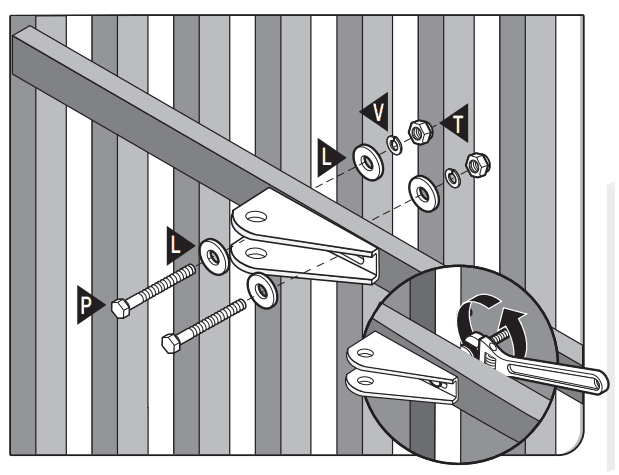
- Secure the gate bracket with the supplied hardware as shown.
Step 11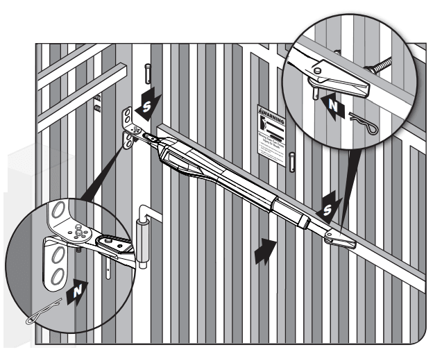
- Once the gate post and gate brackets are installed, reattach the operator’s arm.
- Ensure the operator’s arm is level, adjusting the post bracket location if necessary.
- Once level, ensure all hardware is tight.
- Remove excess bolt length with a hacksaw.
INSTALLING THE CLOSED POSITION STOP PLATE / PULL-TO-OPEN
Step 1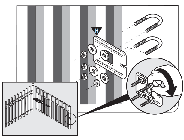
- Remove the operator from the gate post and gate brackets.
- With the gate fully open, install the closed position stop plate (hardware not included).
- Do not fully tighten the hardware until after the next step.
Step 2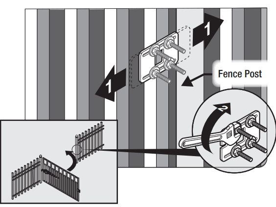
- Swing the gate to the closed position, and adjust the closed position stop plate against the fence post.
- Tighten the mounting hardware.
- Return the gate to the open position and reinstall the operator’s arm.
- To complete the pull-to-open installation, see page 17.
PUSH-TO-OPEN OPERATOR MOUNTING
Step 1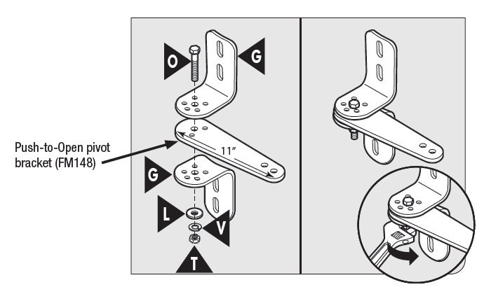
- Assemble the gate post bracket subassembly as shown with the Push-to-Open pivot bracket (FM148). Must be purchased separately.
Step 2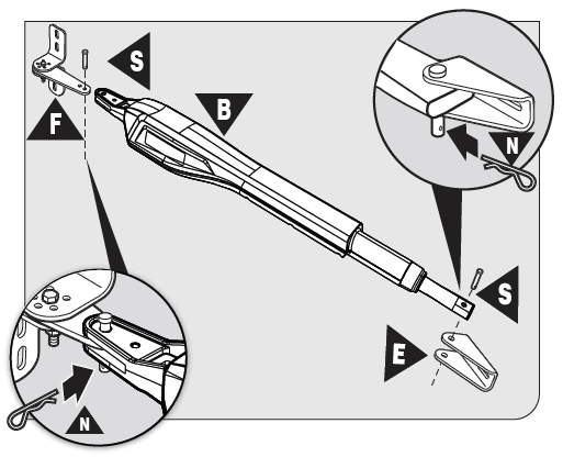
- Attach the gate post bracket subassembly and gate bracket to the operator as shown.
- The operator must be fully retracted with the gate in the desired open position.
Step 3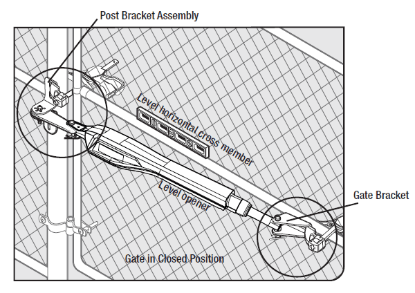
- With the gate in the CLOSED position, use clamps to secure the operator to the gate post and center cross member of the gate.
- Ensure that the operator is level.
- With the operator arm temporarily secured to the gate, check to ensure there is at least 2 inches of clearance between the operator arm and gate. (See illustration in Step 4 below).
Step 4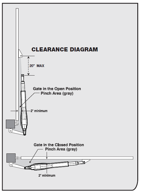
- Disconnect the operator arm from the gate bracket.
- While supporting the operator, swing the gate and operator to the OPEN position.
- Check for recommended clearances and binding as shown.
- Ensure that the necessary arm stroke does not exceed 20 inches.
- Make adjustments to the mounting brackets to achieve the recommended clearances.
TIP: Turning the Push-to-Open bracket (sold separately) over gives more hole alignment options for the gate post pivot bracket assembly.
Step 5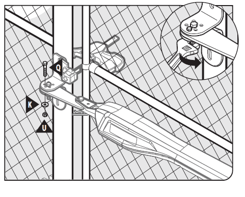
- Close the gate and reattach the operator to the gate bracket.
- Ensure that the operator’s arm is level and the brackets are securely clamped.
- Secure the Push-to-Open pivot bracket in place by installing the hardware shown. Tighten both bolts ‘O’ and ‘Q’.
Step 6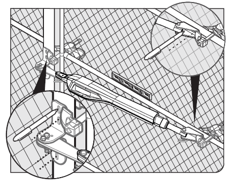
- Using a permanent marker, mark the center of the mounting locations for the gate post bracket subassembly.
- Remove the operator arm from the gate post and gate brackets.
- Mark the center of the mounting locations for the gate bracket.
Step 7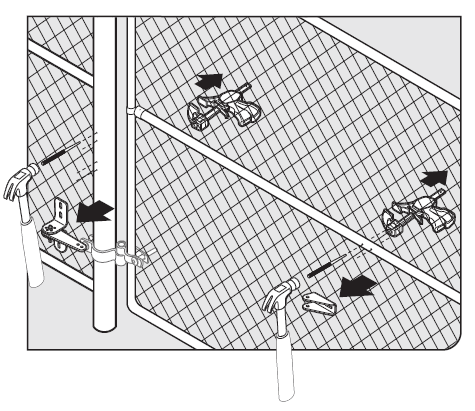
- Remove the gate post and gate brackets.
- Use a hammer and center punch to mark the center of the mounting locations.
Step 8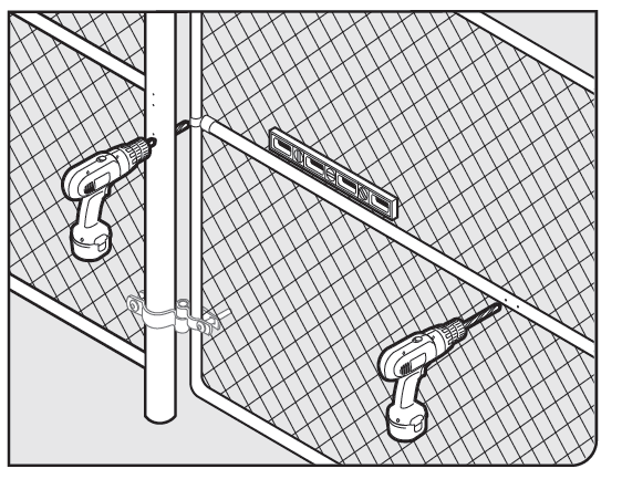
- Using a drill and 7/16” drill bit, drill the necessary holes to mount the gate post and gate brackets.
Note: Some installations may require additional reinforcement to be installed on the gate. See page 16.
Step 9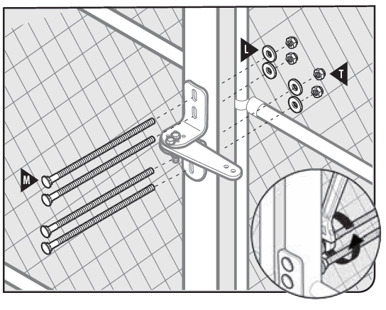
- Secure the gate post bracket subassembly with the supplied hardware as shown.
Step 10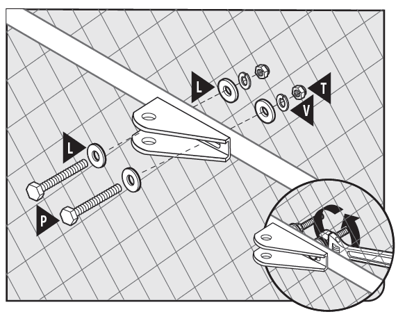
- Secure the gate bracket with the supplied hardware as shown.
Step 11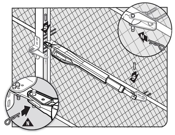
- Once the gate post and gate brackets are installed, reattach the operator’s arm.
- Ensure the operator’s arm is level, adjusting the post bracket location if necessary.
- Once level, ensure all hardware is tight.
- Remove excess bolt length with a hacksaw.
INSTALLING THE CLOSED POSITION STOP PLATE / PUSH-TO-OPEN
Step 1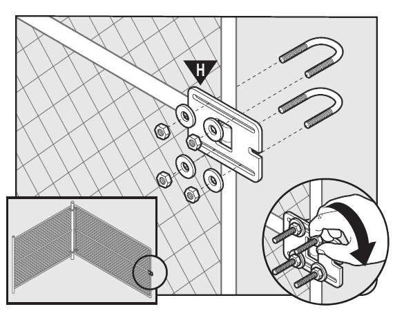
- Remove the operator from the gate post and gate brackets.
- Swing the gate to the open position.
- With the gate fully open, install the closed position stop plate on the gate opposite the operator (hardware not included).
- Do not fully tighten the hardware until after the next step.
Step 2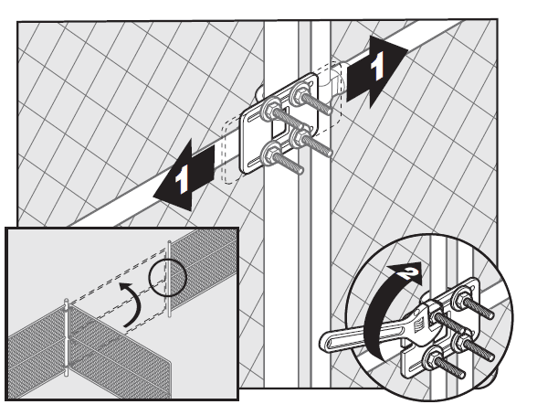
- Swing the gate to the closed position, and adjust the closed position stop plate against the fence post.
- Tighten the mounting hardware.
- With the gate in the closed position, reinstall the operator’s arm.
Maintenance
- Monthly, test the obstruction and entrapment protection systems.
- Monthly, service the gate operator (make sure the power switch is OFF). Clean the extended operator arm with a soft, dry clean cloth.
- On all gates weighing 250 lb. or more, routinely grease the ball bearing hinges at least 4 times a year; more frequently if the gates are near a coastal area.
- Monthly, turn off the power switch disconnect the Mighty Mule, and move the gate to make sure the gate is moving freely without sticking or binding. Lubricate the hinges or repair the gate as required before reattaching the Mighty Mule.
- Monthly, check the gate system for potential entrapments from new landscaping or construction. Eliminate or guard as required.
- Monthly, check that the warning signs are mounted on each side of the gate and clearly visible. Replace the signs if they are missing or damaged.
- Replace batteries every 2-3 years and properly recycle old batteries.
Troubleshooting Guide – Audible Feedback
If your gate operator does not function properly after it is installed, use this guide before calling the Nortek Security & Control Service Department.
| Visual Feedback | Possible Diagnosis | Check/Solution | |
|
The unit does not seem to turn on | Blown fuse(s) Lack of power Power switch | ► Ensure the unit is switched on ► Check fuses ► Battery harness connections ► Battery under load or inadequate charge | |
| Unit requires powercycle in order to reset the error | LED 2 (red) 1 blink, pause, 1 blink,…… | Cycle (CYCL) terminal shorted |
Detach all wires connected to the affected terminal. Turn the system power off and back on. After the start up beep, ensure the system functions as expected. Troubleshoot each accessory that was removed and associated wiring individually.
► Check fuses ► Battery harness connections ► Battery under load or inadequate charge ► Check fuses ► Battery harness connections ► Battery under load or inadequate charge ► AC output at 120 Vac, transformer output at 19 Vdc ► Solar panel(s) output based on weather conditions ► Wiring from charge source to control board, verify correct polarity |
| LED 2 (red) 2 blinks, pause, 2 blinks,…… | Safety (SAFE) terminal shorted | ||
| LED 2 (red) 3 blinks, pause, 3 blinks,…… | Exit (EXIT) terminal shorted | ||
| LED 2 (red) 4 blinks, pause, 4 blinks,…… | Shadow (SHDW) terminal shorted | ||
| LED 2 (red) 5 blinks, pause, 5 blinks,…… | Close Edge (CLOSE EDGE) terminal shorted | ||
| LED 2 (red) 6 blinks, pause, 6 blinks,…… | Open Edge (OPEN EDGE) terminal shorted | ||
| Charge LED rapidly flashing | Unit does not detect the presence of a battery | ||
|
Charge LED off |
Unit not charging | ||
| Charge LED Flashing | Battery or Batteries disconnected | Connect battery/batteries | |
| Visual Feedback | Possible Diagnosis | Check/Solution |
| The unit will not run | 1) Closed / open limit not programmed 2) Transmitter not programmed 3) Battery issues 4) Arm problem | ► Program closed / open limit, see pages 36-37 ► Program transmitter ► Check fuses ► Battery harness connections ► Battery under load or inadequate charge ► Check arm connections to control board, and then turn the system off and back on. If there is a click and no movement, there is an issue with the arm or power cable. |
| The unit stops before reaching the proper open or close position. | Limit position not adjusted/set correctly The unit is receiving a stop command Hardware not positioned correctly | ► Reset the extended limit position. Note: if this problem has occurred, make sure the resetting of limit(s) begins with the operator arm fully retracted. Do not spin the tube out by hand in order to attach it to the gate bracket. ► Adjust the arm’s retracted position by moving or repositioning the hardware. ► Adjust the arm hardware (this would correct the retracted position of the arm) ► Check for a triggered (stuck) transmitter or accessory by removing batteries from all other wireless accessories. |
| The unit reverses before completing an open or close. | Gate/unit has sensed an obstruction | ► Path of gate ► Gate for Level and Plumb ► The gate requires maintenance, it is to difficult to move. ► Adjust Force Factor ► For diagnostic purposes disconnect the external obstruction detection devices, if the unit works troubleshoot these devices. ► Arm rev. counter ► Arm power cable connections. |
| The auto close seems to be working in reverse and/or accessories not operating properly | Dip switch 1 in the wrong position, or was not updated by the system. | ► Turn unit off then back on ► Move dip 1 to the correct position and then turn unit off then back on. ► Check accessories and connections |
| F1 fuse (top left) blown | Transformer or solar wired to board incorrectly | ► Correct wiring ► Replace fuse |
| F2 fuse (bottom left fuse) blown | Battery or Batteries connected incorrectly | ► Check battery connections and harness, ensure the battery is connected red to red (+) and black to black (-) ► Replace F2 fuse and harness fuse if blown |
| Harness fuse blown | Battery or Batteries connected incorrectly | ► Check battery connections and harness, ensure the battery is connected red to red (+) and black to black (-) ► Replace harness fuse and F2 fuse if blown |
For more manuals by Mighty Mule, visit ManualsLibraryy
Mighty Mule TS571W Single Swing Smart Gate Opener-FAQs
Why is my Mighty Mule blinking blue?
The LED flashes blue while attempting to connect to the gate operator. Wait about 5 minutes to see if the system connects at the current power level.
Why does my Mighty Mule gate open by itself?
Wireless interference from remote controls, car alarms, or nearby radio towers can cause unintended gate operation. Electrical interference from other devices may also be a factor.
How do I keep my electric gate open?
If your gate has an automatic closing feature, you can adjust or disable it in the control panel by modifying the timer settings.
How do I connect my Mighty Mule to WiFi?
1. Connect the gate opener to your home Wi-Fi network.
2. Download the Mighty Mule app on your smartphone.
3. Follow the in-app instructions to complete the setup.
What is a remote transmitter?
A remote transmitter, or remote controller, sends radio signals to operate the gate based on your button inputs.
Does the Mighty Mule gate opener require a battery?
Yes, models like FM260, MM271, FM350, MM360, MM371W, MM362, MM372W, MM660, and TS571W require a 12V automotive or lawn tractor battery with at least 250 cold cranking amps (CCA) or the MMB200 Mighty Mule Battery Enclosure Kit.
Why does my Mighty Mule keep beeping?
Beeping may indicate a battery issue, such as a dead cell or lack of charge. Check your power source and battery condition.
How does the Mighty Mule gate opener work?
It has a built-in safety obstruction sensor, which stops and reverses the gate if an obstacle is detected, similar to a garage door opener. The sensitivity of this feature can be adjusted.

