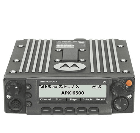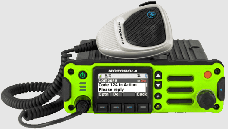
Motorola APX 6500 Mobile Radio

RADIO PARTS AND CONTROLS
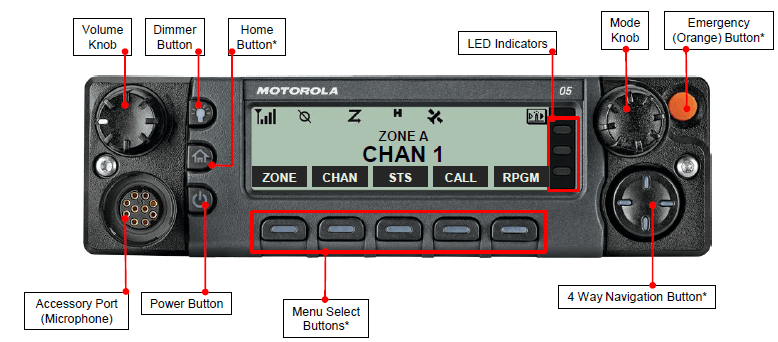
O5 Control Head
These radio controls/buttons are programmable.
PREPARING YOUR RADIO FOR USE
Turning on/off the Radio
Press the Power Button briefly to power on the radio.
After a short time, the red, yellow, and green LEDs light up. The display then shows Zone and channel text, and menu items display on the screen. The backlight will turn on to the last selected dim level.
Note: Pressing the Power Button before the LED lights up will be ignored.
- If FAIL ##/## appears in the display, the radio will not function until the condition has been corrected.
- If ERROR ##/## appears, some non-critical data has been changed.
- If the power-up test is unsuccessful, you see Error XX/YY (XX/YY is an alphanumeric code).
- Turn off the radio, check the battery, and turn the radio back on. If the radio fails the power-up test again, record the Error XX/YY code and contact your dealer.
- If CH MISMATCH appears, it means that either the Control Head has been connected to an incompatible transceiver or vice versa.
If your radio does not power up, contact your dealer.
To turn off the radio, press the Power Button after the LEDs light up.
Adjusting the Volume
To increase the volume, rotate the Volume Knob clockwise.
To decrease the volume, rotate the Volume Knob counterclockwise.
IDENTIFYING RADIO CONTROLS
Emergency
Depending on the programming, initiates or cancels an emergency alarm or call.
Ext PA On/Off
Toggles the audio routing between the connected public address (PA) loudspeaker amplifier and the radio’s internal public address (PA) system.
Information
Displays the basic radio information, IP-related information, and buttons or switches control mapping.
Intercom
Enables users of multiple control heads to talk to each other via the control heads in a multi-control head setup.
Internet Protocol Address
Displays the Internet Protocol (IP) address, device name, and status of the radio.
Location
Determines the current location (latitude, longitude, time, and date), and also the distance and bearing to another location. Or, turns the GPS functionality on or off for all locations.
Message
Enter the current message list.
Monitor (Conventional Only)
Monitors a selected channel for all radio traffic until the function is disabled.
Multiple Private Line (Conventional Only)
Selects the Multiple Private Line lists.
Nuisance Delete
Temporarily removes an unwanted channel, except for priority channels or the designated transmit channel, from the scan list.
One Touch 1 – 4
Launches a specific feature with one single button-press. You can set up as many as four separately programmed buttons for four different features.
Phone
Allows you to make and receive calls similar to standard phone calls.
Private Call (Trunking Only)
Allows a call from one individual radio to another individual radio.
Private Line Defeat (Conventional Only)
Overrides any coded squelch (DPL or PL) that is preprogrammed to a channel.
Radio Profiles
Allows for easy access to a set of preprogrammed visual and audio settings of the radio.
Recent Calls
Allows for easy access to the list of calls recently received or made.
Rekey Request
Notifies the dispatcher that you want a new encryption key.
Repeater Access Button (RAB) (Conventional Only)
Allows manual sending of a repeater access code.
Reprogram Request (Trunking Only)
Notifies the dispatcher that you want a new dynamic regrouping assignment.
Request-To-Talk (Conventional Only)
Notifies the dispatcher that you want to send a voice call.
Scan
Toggles scan on or off.
Scan List Programming
Selects the scan list for editing.
Secure/Clear
Toggles secure transmission on or off.
Select
Selects the assigned list for editing.
Selective Call (Conventional Only)
Calls an assigned radio.
Site Display (Trunking Only)
View the current site or enable a site search for SmartZone operation.
Site Lock/Unlock (Trunking Only)
Locks onto a specific site.
Status (Astro 25 Trunking Only)
Sends data calls to the dispatcher about a predefined status.
Talkaround/Direct (Conventional Only)
Toggles between using a repeater and communicating directly with another radio.
Talkgroup (Conventional Only)
Allows a call from an individual radio to a group of radios.
Text Messaging Service (TMS)
Selects the text messaging menu.
TMS Quick Text
Selects a predefined message.
User Login
Automatically registers with the server.
Zone Down
Toggles downward through the zones on the radio.
Zone Select
Allows selection from a list of zones.
Zone Up
Toggles upward through the zones on the radio.
Assignable Settings or Utility Functions
Dimmer
Changes the display brightness.
Front/Rear
Switches one of two control heads to be active at a time.
TX Power Level
Toggles transmit power level between high and low.
Voice Announcement
Audibly indicates the current feature mode, Zone, or Channel the user has just assigned.
Voice Mute
Toggles voice mute on or off for the channels that have enabled In-Call User Alert. When Voice Mute is active, the radio remains muted to all conventional dispatch calls and affiliated trunking group calls.
Accessing the Preprogrammed Functions
You can access various radio functions in one of the following ways:
- A short or long press of the relevant programmable buttons.
- Use the Menu Select Buttons.
Using the Menu Select Buttons
The Menu Select Buttons allow access to the menu entries of features.
Note: Check with your dealer or system administrator for the list of features activated in your radio.
Your radio may be preprogrammed differently from the following example, but the steps for selecting a zone may appear as shown below:
Press the Menu Select button directly below ZONE.
Using the Advanced Programmable Buttons
This feature is to help you shorten the process of applying certain common features.
(Quick Access) One Touch Button
Enter a menu with a short press on the preprogrammed One Touch button. Features assigned to these buttons are Call, Call Alert, Phone, Repeater Access, MDC RTT Button Access, Status, and Message.
These programmable buttons support the One Touch Button feature.
Using the Navigation Buttons
Home Button
The HOME button returns you to the Home (default) screen. In most cases, this is the current mode.
For selected radio features, the HOME button is also used to save user-edited radio settings or information before returning you to the Home screen.
Note: Some features do not require you to press HOME to go to the Home screen. Refer to the individual feature sections in this manual for further details on saving user-edited radio settings or information.
Dimmer Button
Use this button to adjust the brightness of the display.
Volume Knob
Use this Volume Knob to adjust the volume of the speakers by turning it clockwise or counterclockwise.
Mode Knob
Use this Mode Knob to scroll through the channels by turning it clockwise or counterclockwise.
4-Way Navigation Button
Use this button to scroll up, down, left, or right.
Press and release one of the buttons to scroll from one entry to the next one. Press and hold one of the buttons to have the radio toggle through the list automatically (release the button to stop).
IDENTIFYING STATUS INDICATORS
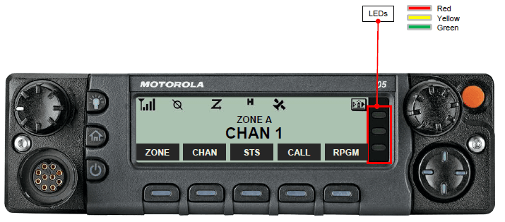
LED Indicator
The LED indicator shows the operational status of your radio.
Solid red
Radio is transmitting.
Rapidly blinking red
Radio has failed the self-test upon powering up or has encountered a fatal error.
Solid yellow (Conventional Only)
The channel is busy.
Blinking yellow
Radio is receiving a secure transmission.
Solid green
Radio is powering up, or is on a non-priority channel, while in the Scan List Programming mode.
Blinking green
Radio is receiving an individual or telephone call, or is on a Priority-Two channel while in the Scan List Programming mode.
Rapidly blinking green
Radio is on a Priority-One channel while in the Scan List Programming mode.
Intelligent Lighting Indicators
| This feature temporarily changes the radio’s display backlight color and the alert text background color to help signal that a radio event has occurred.
Note: This feature must be preprogrammed by a qualified radio technician. | ||
| Backlight and Bar Color | Notification | When |
| Orange | Emergency Alerts | The radio initiates an emergency alarm or call. |
| The radio receives an emergency alarm or call. | ||
| Red | Critical Alerts | The radio is out of range. |
| The radio enters fail-soft mode. | ||
| The radio is unable to establish a full connection with the system. | ||
| The radio is unable to authenticate or register with the system. | ||
| Green | Call Alerts | The radio receives a private call. |
| The radio receives a phone call. | ||
| The radio receives a call alert. | ||
| The radio receives a selective call. | ||
IDENTIFYING STATUS INDICATORS
Orange
Emergency Alerts
Red
Critical Alerts
Green
Call Alerts
GENERAL RADIO OPERATION
Selecting a Zone
A zone is a group of channels.
Procedure:
- Left or Right to ZONE.
- Press the Menu Select button directly below ZONE.
- Left or Right to the required zone.
- Press HOME or the PTT button to confirm the selected zone.
- Press the PTT button to transmit in the displayed zone.
Selecting a Radio Channel
A channel is a group of radio characteristics, such as transmit/receive frequency pairs.
Procedure:
Mode knob
- Rotate the Mode knob until the display shows the desired channel.
- Press the PTT button to transmit on the displayed channel.
Making a Radio Call
You can select a zone, channel, subscriber ID, or talkgroup by using:
- The preprogrammed Zone menu
- The Mode Knob
- A preprogrammed One Touch Call button
- The Contacts list
Note: If the feature inactivity timer is enabled, your radio automatically exits the feature when your radio is left idle long enough for the time to expire. You will hear the Menu Inactive Exit Tone upon feature exit.
ADVANCED FEATURES
Multiple Control Head Features
This feature allows a transceiver to control a combination of up to four O5 control heads on APX Mobile (depending on the model).
You can use the CAN cables to connect in any configuration that does not exceed 131 feet (40 meters) in combined length.
Refer to the O5 Control Head Installation Manual (HLN6947) for further information.
The Multiple Control Head (MCH) feature consists of 2 modes that can be programmed via Customer Programming Software (CPS):
- All Active mode
- One Active mode
Note: If two or more control heads are connected to the system before enabling the MCH feature in the CPS, the radio will display EXTRA CH or CH ID # ERR. Both errors are FATAL.
Multiple Control Head Features
All Active Mode
The All Active mode enables all connected control heads attached to the radio to operate concurrently with each other. When you activate a feature on one control head, the rest of the control heads will have the same activated features and indicators on their respective display.
Note: The multiple control head feature allows only control heads of the same type to be connected. Upon power up, if a control head of a different type is connected to the radio, the radio reports the FATAL error CH MISMATCH on the display of all attached control heads.
Intercom Feature in All Active Mode
The intercom feature allows one control head user to talk to another control head user in a Multiple Control Head configuration. At any given time, when a control head being operated has priority for the intercom call, all other control heads are blocked until the active control head releases the PTT button.
This can be made on any attached control head. This feature only applies to control heads in the All Active mode.
Procedure:
- Press the Menu Select button directly below INTC to activate the intercom feature of any of the control heads.
- Press the PTT button to initiate an intercom transmission. All control heads that are attached will receive the same intercom call. The display of the control heads receiving the intercom call shows the alias/ID number of the transmitting control head.
- Press the Menu Select button directly below EXIT to deactivate the intercom feature.
- Press HOME to deactivate the intercom feature.
The intercom feature also deactivates when the user initiates a mode change.
If the radio is on an emergency channel, pressing the Emergency button or the emergency footswitch button on any control head also deactivates the intercom feature.
Scan Lists
Scan lists are created and assigned to individual channels/groups.
Your radio scans for voice activity by cycling through the channel/group sequence specified in the scan list for the current channel/group.
Your radio supports different types of Scan Lists:
- Trunking Priority Monitor Scan List
- Conventional Scan List
- Talkgroup Scan List
A maximum of 200 Scan Lists can be programmed in your radio. These lists must be preprogrammed by a qualified radio technician.
Scan
Hang Up Box (HUB)
To temporarily suspend Scan Mode operation, remove the control head from the Hang Up Box (HUB). You are allowed to use the control head while the scan is suspended.
However, Priority Member scanning is not suspended. This feature applies to all Scan Lists and Scan Types. Scan is resumed once the control head is returned to the holding clip and the preprogrammed hang time has elapsed.
Note: Priority Scan List members are continuously scanned only when the Scan List, Designated Tx Member field is set to “Talkback” in the radio programming. Otherwise, all scan mode operation is suspended.
The Emergency feature is used to indicate a critical situation.
If the Orange button is preprogrammed to send an emergency signal, this signal overrides any other communication over the selected channel.
Your radio supports the following Emergency modes:
- Emergency Alarm
- Emergency Call (Trunking Only)
- Emergency Alarm with Emergency Call
- Silent Emergency Alarm
- Special Considerations for Emergencies
Check with your dealer or system administrator for more information on the programming of this feature.
Only one of the Emergency modes above can be assigned to the preprogrammed Emergency button or the Emergency footswitch.
Note: To exit emergency at any time, press and hold the preprogrammed Emergency button for about a second.
Emergency Operation
Sending an Emergency Alarm
This feature allows you to send a data transmission, which identifies the radio sending the emergency, to the dispatcher.
Procedure:
- Press the preprogrammed Emergency button. A tone sounds, and the display alternates between EMERGENCY and the home display.
A dispatcher acknowledgment, ACK RECEIVED, displays as follows.
AND, Trunking Only:
A high-pitched tone indicates that the alarm has been received by the trunked system’s central controller.
- Press and hold the emergency button or the PTT button to return to normal operation.
Special Considerations for Emergencies
- If you press the emergency button while in a channel that has no emergency capability, a low-pitched tone sounds.
- If the unit is out of the range of the system and/or the emergency alarm is not acknowledged, a tone sounds, and the display shows NO ACKNOWLEDGE.
- If you press the emergency button, then change to a mode that has no emergency capability, the display shows NO EMERGENCY, and a continuous low-pitched tone sounds until a valid emergency mode is selected or until the emergency is cancelled.
- When an emergency is active, changing to another mode where emergency is enabled (trunked or conventional) causes an emergency alarm and/or emergency call to be active on the new mode.
Trunking System Controls
Using the Fail-soft System
The fail-soft system ensures continuous radio communications during a trunked system failure.
If a trunking system fails completely, the radio goes into fail-soft operation and automatically switches to its fail-soft channel.
The fail-soft condition is indicated by a faint beeping tone every nine seconds (radio unsquelched) until the trunking system returns to normal operation.
To continue, in Fail-soft, to communicate with other talkgroups, refer to the following procedure.
Procedure:
- Rotate the Mode Knob to change to a different repeater frequency.
- Press the PTT button to talk, and release the button to listen.
When the trunking system returns to normal operation, your radio automatically leaves fail-soft operation and returns to trunked operation.
For more Manuals by Motorola, visit ManualsLibraryy
Motorola APX 6500 Mobile Radio-FAQs
What does the purple button on my Motorola radio do?
The purple button, located near the top side of the radio, controls scanning. A short press turns scanning on or off, while a long press allows you to edit the scan list.
Does the Motorola APX 6500 have GPS?
Yes, the APX 6500 includes GPS tracking functionality, which supports location-based services and improves safety during critical operations.
What does the “H” symbol mean on my radio display?
The “H” indicates that the radio is operating at high power. If you see a blinking dot, it means the radio is detecting activity on the Priority-One channel while scanning; a solid dot represents activity on the Priority-Two channel.
What is the function of the orange button?
The orange button is the emergency alert button. Pressing it sends an emergency signal and activates an alarm to alert others to your situation.
What is a radio button used for?
In digital interfaces, radio buttons are used to select one option from a list of mutually exclusive choices, such as preferences or settings.
Why is the LED on my Motorola radio blinking green?
A blinking green light means the battery has reached 90% charge. Leave it in the charger until the light becomes steady green, which indicates a full charge.
How do I use the scan feature on the APX 6500?
Press and hold the Scan button until a flashing box appears on the screen. Turn the channel knob to choose a channel, then press the side light button (blue) to add or remove it from your scan list or assign priority.
Can I program the Motorola APX 6500 myself?
Yes, Motorola radios, including the APX series, can be programmed using the appropriate software. This includes setting frequencies, channels, and other custom features.


