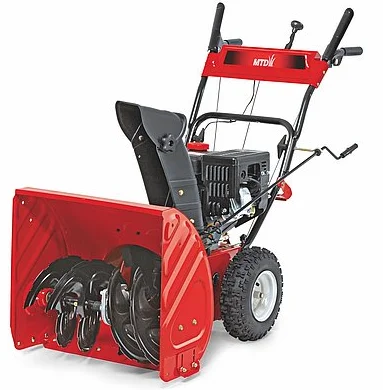
MTD 190-032-101 Two Stage Snow Thrower Operators
Carton Contents
If you are missing any parts, please do not contact the retailer where you purchased this unit; call MTD directly at 1-330-220-4MTD or toll-free at 1-800-800-7310.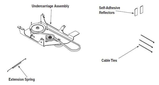
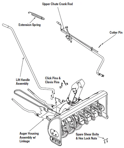
Before beginning installation, remove all parts from the carton to make sure everything is present. Carton contents are listed below and shown in Figure 3. Hardware part numbers are shown in parentheses.
- One Auger Housing Assembly w/ Lower V-belt
- One Undercarriage Assembly w/ Upper V-belt
- One Lift Handle Assembly
- One Upper Chute Crank Rod
- Three Cable Ties (725-0157)
- Two Spare Shear Pins (738-04124) & Cotter Pins (714-04040)
- One Cotter Pin (714-0507)
- Two Self-adhesive Reflectors (730-3000)
- Extension Spring (732-04237)
- Extension Spring (732-04237)
- Clevis Pin (711-0332)
- Click Pin (714-0145)
Assembly
Model Series 600-649 & All 800 series.
WARNING: Before installing the attachment, place the tractor on a firm and level surface. Place the PTO in the disengaged (OFF) position, set the parking brake, shut the engine off, and remove the key to prevent unintended starting.
NOTE: References to LEFT and RIGHT indicate the left and right sides of the tractor when facing forward in the operator’s position. Reference to the FRONT indicates the grille end; to the REAR the drawbar end.
IMPORTANT: You must first figure out which model of rider you are attaching this snow thrower to. Refer to Determine Your Model of Rider on page 3 of this manual to determine which model rider you are attempting to install this attachment to. Then proceed to the applicable instructions for your model of rider.
Your tractor’s cutting deck, PTO belt, and front deck stabilizer bracket must be removed prior to mounting the snow thrower attachment. Refer to your tractor’s Operator’s Manual for detailed instructions. If your tractor is equipped with any front-end accessory (i.e., front bumper kit), it must also be removed.
Do you have an Electric PTO or a Manual PTO?
If you engage your tractor’s cutting deck by using your left hand to pivot a lever forward, your tractor has a Manual PTO. If you engage your tractor’s cutting deck by pulling outward on a small knob located on the tractor’s dashboard, your tractor has an Electric PTO.
Mounting the Idler Assembly
Electric PTO Undercarriage Assembly Setup
Proceed as follows when mounting this snow thrower attachment to a tractor equipped with a 42, 46, 50, or 54-inch deck with electric PTO:
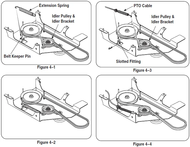
- Attach one end of the extension spring (732-0594A) to the hole in the idler assembly. Mount the opposite end of the extension spring to the belt keeper pin as illustrated in Figure 4–1.
- Refer to Figure 4–2 for the correct position.
Manual PTO Undercarriage Assembly Setup
- Attach the PTO cable to the idler bracket, then fit the cable into the slotted fitting as seen in Figure 4–3.
NOTE: The PTO cable should hang down under your tractor after you remove the mowing deck. You will need to slide the undercarriage unit under your tractor in the position for which it will be mounted. The slanted side should be pointed towards the front of your tractor.
- Refer to Figure 4–4 for the correct position.

Mounting The Undercarriage Assembly
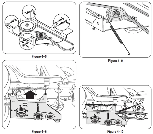
- Remove and retain the four hairpin clips from the weld pins found on the top side of the undercarriage assembly. Remove and retain the two clevis pins with hairpin clips. This hardware is for later installation. See Figure 4–5.
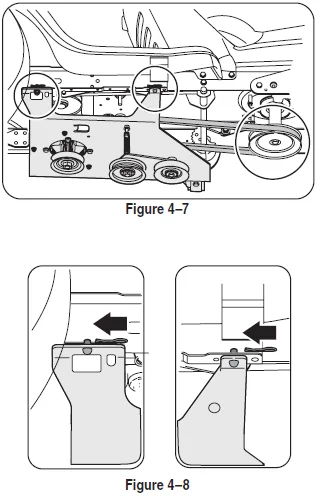
- With the undercarriage assembly beneath the tractor (see figure 4–6, lift the undercarriage assembly up against the frame of the tractor. The weld pins on the top of the undercarriage assembly should go through the aligning holes found along the tractor’s frame. See Figure 4–7.
- Fasten the undercarriage assembly to the frame with the hairpin clips removed in step 1. See figure 4–8
- Route the upper drive belt around the engine pulley. See Figure 4–7. NOTE: Proceed to the Assembling Controls section of this manual if you have an Electric PTO.
- Attach the extension spring to the idler pulley. See figure 4–9. Connect the other end to the tractor’s frame rail. See Figure 4–10.

Assembling Controls
NOTE: All references to the left or right side of the snow thrower are from the operating position only.
Attaching Chute Directional Control
- Attach the chute directional control assembly to the upper lift link on the left side of the auger housing. Assemble with two hex screws and washers as illustrated in Figure 6–1. Secure with two flange nuts.
- Secure the upper chute crank rod to the joint block (A) on the lower chute crank rod with the cotter pin (B) provided. See Figure 6–2.
- Fasten the chute tilt cables to the chute directional control with two of the cable ties provided. Pull cable ties until snug and trim excess.
Attaching Lift Handle
- Attach the lift handle to the lift bracket on the right side of the auger housing assembly with two hex screws and two flange nuts provided. See Figure 6–3.
- Fasten the lift cable to the lift handle with two of the cable ties provided. Pull the cable ties until snug and trim excess.
Mounting Auger Assembly
WARNING: Before installing the attachment, place the tractor on a firm and level surface. Place PTO in the disengaged (OFF) position, set the parking brake, shut the engine off, and remove the key to prevent unintended starting.
IMPORTANT: If you are installing this snow thrower attachment on any tractor model with a side discharge muffler (See Figure 6–4, then the heat shield on the auger housing must be removed. See figure 6–5.
To remove the heat shield, remove the four lock nuts and bolts (two on either side of the unit), securing the heat shield to the lift linkage. See figure 6–5.
IMPORTANT: It will be necessary to have a second person assist you to complete the following steps.
- Position the auger housing assembly in front of the tractor as seen in Figure 6–6. Lay the belt and support tubes on the installation surface.
- Carefully move the tractor forward (by pushing, NOT driving it) so that the support tubes found on the rear of the auger housing assembly are positioned between the tractor’s front tires. Set the parking brake.
- With the help of an assistant, lift up the auger housing and move it so that it rests over the shoulder bolts found on the tractor. See Figure 6–7.
- Maneuver the auger housing until the mounting holes line up. Insert the clevis pins from your hardware pack and secure with the click pins. See Figure 6–8.
Attaching Support Tubes
- Secure the left support tube to the front of the undercarriage assembly with the clevis pin and hairpin clip removed earlier. See Figure 6–9.
- Repeat the previous step on the right side.
Attaching Reflectors
Peel off the backing from each of the reflectors to expose the adhesive surface. Attach the reflectors to the rear of the tractor’s fender (one on the left and one on the right) so that the reflectors simulate taillights.
Belt Routing: Various Models
WARNING
Before installing the attachment, place the tractor on a firm and level surface. Place the PTO in the disengaged (OFF) position, set the parking brake, shut the engine off, and remove the key to prevent unintended starting.
IMPORTANT: Make certain that the flat side of the belt is facing outward. This allows the “V” side of the belt to ride snugly in both pulleys.
Routing the Upper Drive Belt (Tractor Models with an Electric PTO)
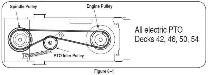
Attach and route the upper drive belt around the spindle pulley and idler pulley found on the undercarriage, the electric PTO clutch, and the PTO idler pulley as illustrated in Figure 8–1. Make sure that the belt is routed to the INSIDE of the belt keeper on the undercarriage idler pulley and the remaining keeper pins found around the spindle pulley.
IMPORTANT: Make certain that the flat side of the belt is facing outward as it sits against both the electric PTO clutch and spindle pulley. This allows the “V” side of the belt to ride snugly in both pulleys.
Routing the Upper Drive Belt (Tractor Models with a Manual PTO)
Attach and route the upper drive belt around the engine pulley and spindle pulley, routed to the INSIDE of the PTO idler pulley on the undercarriage. Make sure the belt is routed inside the belt keeper pins found around the spindle pulley and engine pulley. See Figure 8–2.
IMPORTANT: Be certain the flat side of the belt is facing outward. This allows the “V” side of the belt to ride snugly in both pulleys.
Routing the Lower Drive Belt (All Tractor Models)
- Attach and route the lower drive belt around the lower pulley on the spindle assembly, both pulleys on the double idler bracket found beneath the undercarriage, and the drive pulley found on the rear of the snow thrower housing, as illustrated in Figure 8–3.
- Attach the tension spring (found on the undercarriage double-idler bracket) to the hex screw if it is not already attached.
WARNING: Be familiar with all controls and their proper operation. Know how to stop the machine and disengage it quickly.
Controls
WARNING
Be familiar with all controls and their proper operation. Know how to stop the machine and disengage it quickly.
NOTE:
The PTO knob (on units so equipped) cannot be in the engaged (ON) position when the tractor is driving in the reverse direction. The PTO knob must be in the disengaged (OFF) position when the shift lever is placed in REVERSE, or the electric PTO clutch will automatically shut off.
Engaging the Augers and Impeller
Power to the snow thrower attachment is activated by engaging the tractor’s PTO.
- Place the tractor’s throttle control in the FAST (rabbit) position and allow it to remain there for efficient snow removal.
- Move the PTO knob or PTO lever (on tractors so equipped) into the “ON” position to engage the augers and impeller.
- Move the PTO knob or PTO lever (on tractors so equipped) into the “OFF” position to disengage the augers and impeller.
NOTE: The PTO knob (on units so equipped) cannot be in the engaged (ON) position when the tractor is driving in the reverse direction. The PTO knob must be in the disengaged (OFF) position when the shift lever is placed in REVERSE, or the electric PTO clutch will automatically shut off.
Refer to your tractor’s Operator’s Manual for more information regarding your tractor’s PTO and safety interlock system.
Lift Handle
The lift handle is located on the right side of the tractor and is used to raise and lower the snow thrower attachment.
- To raise the snow thrower attachment off the ground, pull rearward and down on the lift handle until you feel the lift latch on the right side of the snow thrower engage, locking the snow thrower in a raised position. See Figure 9–1.
- To lower the snow thrower, push downward on the lift handle until there is enough slack in the lift cable so that you may squeeze the trigger control. With the trigger control squeezed, gently allow the snow thrower to lower until it reaches the ground.
Chute Directional Control
The chute directional control assembly is found on the left side of the tractor and includes both the chute tilt lever as well as the chute crank. Both affect the direction that the discharged snow is thrown.
To pivot the upper section of the discharge chute, affecting the distance and angle at which the snow is thrown, move the chute tilt lever forward or rearward into a desired position.
The direction in which snow is thrown can be changed by rotating the discharge chute with the chute crank. Turn the chute crank clockwise to rotate the chute and discharge snow to the left. Crank it counterclockwise to rotate the chute and discharge snow to the right.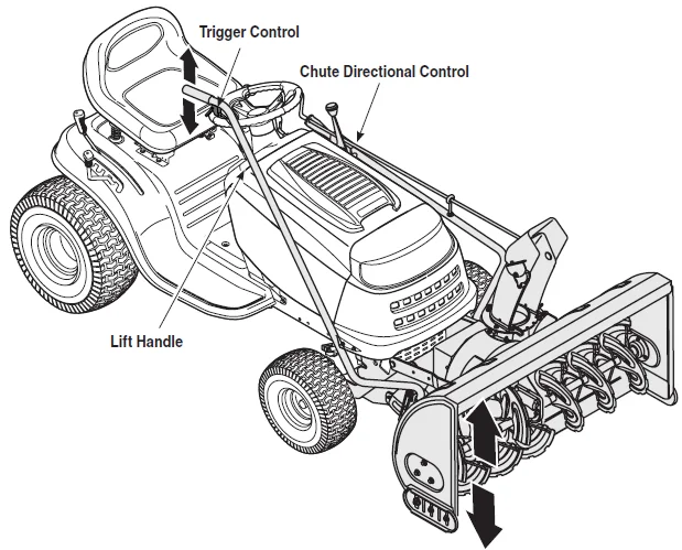
OPERATION
WARNING: Read, understand, and follow all instructions and warnings on the tractor, attachment, and in the Operator’s Manuals before operating.
Your snow thrower attachment is capable of displacing snow and clearing a path a width of 42 inches.
Observe the following operating instructions for efficient snow removal.
- Become familiar with and comfortable using all of your tractor’s controls as instructed in your tractor’s Operator’s Manual before operating it with the snow thrower attachment.
- Make certain the correct weight (and volume) of motor oil is in your tractor’s engine as instructed in the engine Owner’s Guide packed with the tractor’s Operator’s Manual.
- Always operate the snow thrower with the tractor’s engine at maximum RPM (full throttle).
- NEVER override any safety features on either your tractor or the snow thrower attachment.
- Make certain that all nuts, bolts, and hardware are fastened securely and tight on both the tractor and the snow thrower attachment prior to use.
- Make certain the snow thrower is assembled properly and mounted to the tractor as instructed in this manual.
- Test all controls (tractor PTO, snow thrower lift handle, chute tilt lever & chute crank) for smooth operation prior to operating the snow thrower in snow.
- Make all adjustments (i.e., skid shoes, lift latch) before operating your snow thrower attachment. Follow instructions in the Adjustments section of this manual when doing so.
- Engage the tractor’s PTO to activate power to the augers and impeller BEFORE driving the tractor forward and into snow.
- Keep your tractor’s ground speed slow. The slower your tractor is traveling, the more effectively the snow thrower attachment can displace snow.
- Adjust ground speed for snow conditions and become familiar with different snow applications. Your snow thrower attachment will operate differently in wet, heavy snow than it will in light, fluffy snow.
- Overlap a previously cleared path when necessary (deep snow) so as not to overload the auger housing with snow.
- NEVER drive the tractor into a snow bank. The snow thrower attachment is not a dozer plow. The lift linkage and/or the snow thrower drive system can be damaged as a result of “plowing” with the snow thrower attachment.
Maintenance
WARNING: Before lubricating, repairing, or inspecting, place the tractor on a firm and level surface. Place the PTO in the disengaged (OFF) position, set the parking brake, shut the engine off, and remove the key to prevent unintended starting.
Lubrication of Chute Directional Control
The spiral on the end of the lower chute crank, the base of the discharge chute itself, and the joint blocks which connect the lower and upper chute cranks should be lubed with multi-purpose automotive grease once a season. See Figure 12–1.
Auger Shaft
At least once a season, remove the shear bolts on the auger shaft. Oil or spray lubricant inside and on the plastic bearings on the shaft and near the holes where the shear bolts were removed before reattaching them. See Figure 12–2.
Customer Support
If you have difficulty assembling this product or have any questions regarding the controls, operation, or maintenance of this unit, you can seek help from the experts. Choose from the options below:
- Visit www.mtdproducts.com. Click on the Service & Support menu option.
- Phone a Customer Support Representative at 1-800-800-7310.
- Please have your unit’s model number and serial number ready when you call. See above to locate this information. You will be asked to enter the serial number in order to process your call.
For more Manuals by MTD Holdings, visit ManualsLibraryy
MTD 190-032-101 Two Stage Snow Thrower-FAQs
What are the main parts of a two-stage snow blower?
Key parts include spark plugs, fuel filters, carburetor kit, primer bulb, scraper bar, electric starter gear, augers (front, right, and left), drive or traction belt, shear pins, wheels, and ignition key.
How does a two-stage snow blower work?
A two-stage snow blower uses an auger to collect snow and an impeller to throw it through the discharge chute, allowing for efficient snow removal even in deep or heavy conditions.
How do I start my MTD snow blower?
Make sure the fuel valve is open, set the throttle to “Fast,” and close the choke. Pull the starter cord or use the electric starter. Once the engine warms up, gradually open the choke.
Should the choke be open or closed when starting a snow blower?
Always start with the choke closed, especially when the engine is cold. Once it starts, slowly move the choke to the open position.
Why is my snow blower running but not throwing snow?
This often happens when a belt slips off or breaks. Check the auger and drive belts—replace them if they’re worn or stretched.
What should I do if my snow blower won’t start?
Check for fuel, spark plug condition, and carburetor clogging. Cleaning or replacing these parts usually fixes the issue.
Why does my snow blower start and then shut off?
This could be due to a clogged carburetor or stale fuel. Drain the old gas and clean the carburetor to restore normal operation.
What happens if I leave the choke on too long?
Leaving the choke on after the engine warms up causes poor performance, high fuel consumption, and potential engine damage.
How do I know if my snow blower’s carburetor is clogged?
If your snow blower runs rough, stalls, or won’t start at all, a clogged carburetor is likely the problem. Clean or rebuild it to ensure smooth operation.


