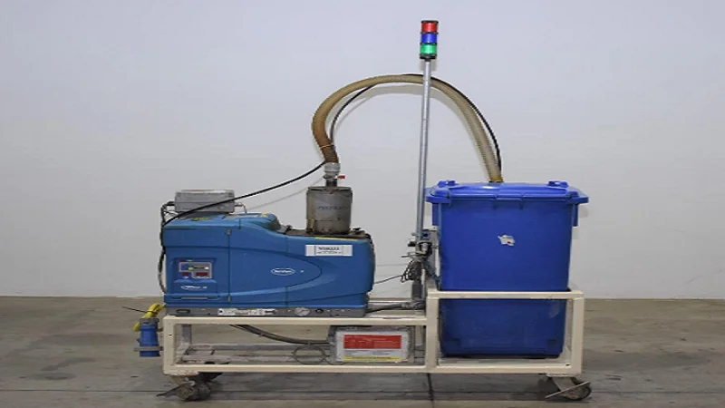
Nordson Fulfill Retrofit Adhesive Fill Kit
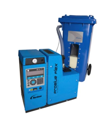
Description
The Fulfill retrofit kit for 100-liter DuraBlue and VersaBlue adhesive melters converts a melter into an automatic fill system that maintains adhesive in the melter, improving productivity and reducing maintenance. The fill system adds adhesive to the sealed tank, reducing the possibility of char, contaminants, thermal shock, and incorrect adhesive temperatures that result in poor adhesive bonding.
The Fulfill system is shipped with the components illustrated in Figure 2.
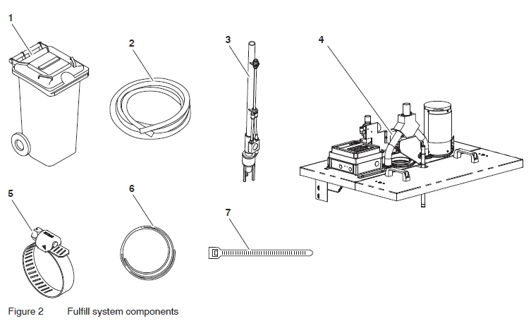
- Adhesive storage bin
- Transfer hose
- Suction lance
- Fulfill the lid assembly, with the control box, the level sensor, and the mounting hardware
- Hose clamp (2)
- Airline (4 m)
- Wire tie (5)
Optional accessories available for the Fulfill retrofit include:
- a vibrator kit for the adhesive storage bin
- a light tower kit for audio/visual fill/fault indication of the fulfillment processes
Contact your Nordson representative for more information on these kits.
Theory of Operation
Overview
The system adds small quantities of adhesive to the sealed tank at regular intervals, reducing the possibility of adhesive char, contaminants, thermal shock, and incorrect adhesive temperatures that result in poor bonding. A capacitance sensor located in the melter detects a low adhesive level and then sends a signal to the Fulfill system control box. A delay timer prevents the fill system from frequently cycling on and off.
At the end of the delay, the control box activates the vacuum via a solenoid valve. Air pressure flows to a suction lance that is placed in the supplied bulk adhesive container. Using a vacuum, the system conveys adhesive from the bulk container to the adhesive melter tank. When the adhesive in the melter tank reaches the desired level, the control box shuts off the solenoid valve to stop the flow of adhesive.
The control box activates the suction lance for a limited amount of time to prevent overflow conditions. If the maximum fill time is exceeded, the control box activates a fault that stops the system from filling.
A safety interlock switch detects whether the removable melter tank lid is in place. If the tank lid is not in place, the fill system will not operate.
Pneumatic and Mechanical Components
See Figure 3 as you learn about the components of the Fulfill retrofit assembly.
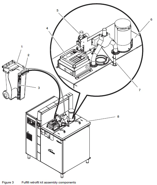
- Adhesive storage bin
- Adhesive transfer hose
- Suction lance
- Control box assembly
- Air pressure regulator/solenoid (pneumatic control unit) assembly
- Fulfill the lid assembly
- Level sensor probe
- Melter tank lid
Adhesive Storage Bin
Place adhesive in the adhesive storage bin. The bin contains a gasket that prevents debris from entering the bin. For best results, break up the adhesive as much as possible when emptying it into the bin. Do not get the adhesive wet.
Air Pressure Regulator/Solenoid Assembly
The supplied air pressure regulator is permanently set at 65 psig, the optimal setting for most adhesives.
The solenoid valve turns on after the sensor indicates the level state and the time delay has been reached. The solenoid directs compressed air to flow to the suction lance.
Suction Lance
The suction lance draws adhesive from the adhesive storage bin. The suction lance includes:
- A venturi pump to draw in and transport the adhesive.
- A vibrator to keep the adhesive in a loose condition. The vibrator is active as long as compressed air is supplied to the suction lance.
Airline tubing and the adhesive transfer hose are connected to the suction lance. The lance is placed in the PVC pipe located in the adhesive storage bin.
Adhesive Transfer Hose
The adhesive transfer hose connects the suction lance to the lid assembly. The transfer hose conveys adhesive from the adhesive storage bin to the melter tank.
Lid Assembly
The Fulfil lid assembly includes the filter stack, lid, fill tube, baffle, and deflector:
- The filter stack contains a replaceable filter sock to prevent adhesive fines and powder in the adhesive from being emitted into the ambient air.
- The fill tube attaches to the adhesive transfer hose.
- The baffle prevents adhesive from entering the filter sock.
- The deflector distributes adhesive evenly in the tank.
A safety interlock switch detects whether the removable melter tank lid is in place. If the tank lid is not in place, the fill system will not operate.
Electrical Components
Control Box
The control box contains the membrane panel and refill board.
Membrane Panel
The front panel of the electrical control box shown in Figure 4 contains three LEDs that have different colored lights to indicate the unit’s condition:
- Enable On/Off LED (green light)—Indicates that the system is enabled. Pressing the Enable On/Off key will toggle the indicator. If the melter tank lid is removed, this LED will flash, indicating that the fill system is disabled.
- Enable On/Off key—Press the Enable On/Off key to turn the fill system on or off.
- Adhesive transfer LED (blue light)—Indicates adhesive delivery is active. When a low level is detected, the indicator notes that adhesive is being transferred from the adhesive storage bin into the melter tank through the transfer hose.
- Fault LED (red light)—Activates if the system exceeds the user-defined fill time limit. The system will not resume operation until the fault is cleared by pressing the Clear Fault key.
- Clear Fault key—Press the Clear Fault key to reset the fault status and resume normal activity.
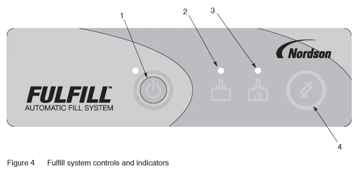
- Enable the On/Off key and the LED (green)
- Adhesive transfer LED (blue)
- Fault LED (red)
- Clear Fault key
Refill Board
See Figure 5. The refill board is inside the control box:
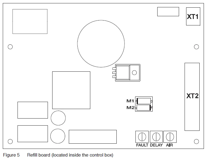
- Connect the line voltage to the control box at the supplied terminal block and ground. Power can be supplied from the plant service.
- A potentiometer labeled “Fault” limits the amount of filling time in case of level sensor failure. It is only for overflow protection. The fault limit time is preset from the factory at 60 seconds, but can be adjusted from 5 to 115 seconds. The factory sets the potentiometer at the 12 o’clock position, which is sufficient for the majority of applications. For reference, the 9 o’clock position is 22 seconds, and the 3 o’clock position is 98 seconds.
- A potentiometer labeled “Delay” is for a fill time delay. This delay is the time duration between the level sensor calling for more adhesive and when the fill system activates. The delay time prevents the system from frequently turning on and off. The delay time is preset from the factory at 60 seconds, but can be adjusted from 0 to 119 seconds. The factory sets the potentiometer at the 12 o’clock position, which is sufficient for the majority of applications. For reference, the 9 o’clock position is 20 seconds, and the 3 o’clock position is 100 seconds.
- A potentiometer labeled “AIR” is a pre-vibration timer for the optional storage bin vibrator kit. The range for this potentiometer is 0 to 20 seconds. When installed, this vibrator will activate up to 20 seconds before the fill system activates and stay on until the level sensor is satisfied. This kit is well-suited for adhesives and plant conditions that are prone to bridging.
- A dip switch labeled SW1 is preset at the factory. Position M1 should always be OFF, and position M2 should always be ON.
- A terminal block labeled “XT2”. An optional light tower may be attached here. The functions of the light tower are
- Fill (Blue)—visual
- Fault (Red)—visual
- Fault (Alarm)—audible
NOTE: The fault outputs will engage simultaneously.
Sensor
The level sensor detects the level of adhesive in the melter tank. When the adhesive falls below the set point, the level sensor sends a signal to the Fulfill control box. For optimal performance based on specific applications, see the Level Sensor Adjustment and Calibration detailed later in the manual.
Installation
![]() WARNING! Allow only personnel with appropriate training and experience to operate or service the equipment. The use of untrained or inexperienced personnel to operate or service the equipment can result in injury, including death, to themselves and others, and damage to the equipment.
WARNING! Allow only personnel with appropriate training and experience to operate or service the equipment. The use of untrained or inexperienced personnel to operate or service the equipment can result in injury, including death, to themselves and others, and damage to the equipment.
Remove the Melter Lid
- Operate the melter until the adhesive level is at least 0.2 m (8 in.) below the top of the tank.
- De-energize the system as directed in the Maintenance section of the melter manual.
- Remove the front and rear panels from the melter. Refer to the melter manual as needed.
- Open the tank lid completely.
- Remove the four M8 screws and washers that secure the lid hinge assembly to the melter.
- Remove the lid assembly from the melter by lifting it straight up.
- Clean any adhesive buildup from the melter lid tray.
Install the Fulfill Lid Assembly
See Figure 6.
- Position the Fulfill lid assembly (1) on top of the melter.
- Ensure that the ground wire (3) from the lid assembly is routed to the front of the tank as shown.
- Remove one screw from the underside of the tank flange and install the spade terminal (4) from the kit as shown.
- Connect the ground wire to the spade terminal.
- Secure the lid assembly to the melter with the four M8 screws, flat washers, and nuts (2) from the kit.
- Reinstall the front and rear melter panels.
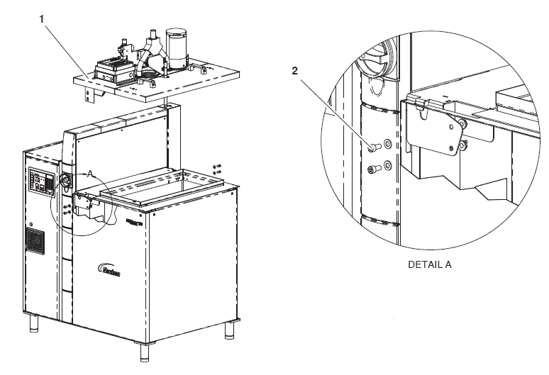
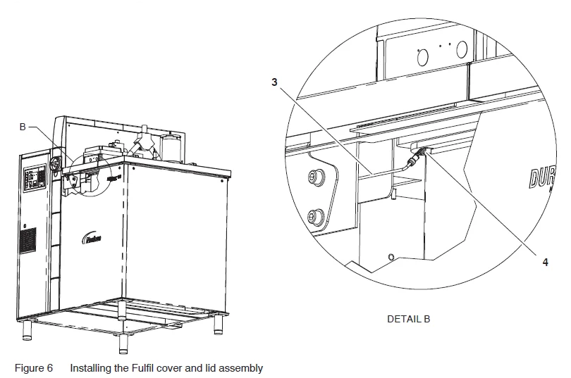
- Fulfill the lid aassembly
- Lid screws
- Ground wire
- Ground wire spade terminal
Make the Electrical Connections
- See Figure 7. Thread the customer-supplied 14−18 AWG power cord through the strain relief (3) into the control box.
- Connect the wiring to the terminal blocks (1) and the ground wire connection (2) inside the control box.
- Tighten the strain relief.
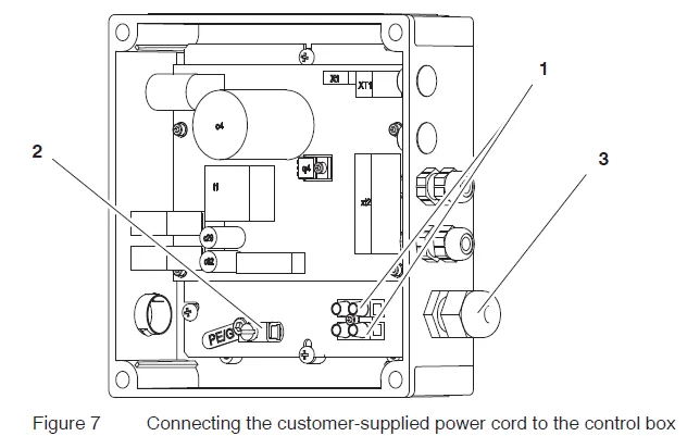
- L1 and L2/N wire power cord connection (interchangeable)
- Ground wire power cord connection
- Power cord strain relief
Assemble the Transfer Hose, Air Line, and Suction Lance
CAUTION! Allow for a 10 in. bend radius for installation/use of the adhesive transfer hose.
See Figure 8.
- Using one hose clamp, attach the transfer hose (1) to the end of the suction lance (5).
- Insert the suction lance into the PVC pipe inside the adhesive storage bin.
- Use the remaining hose clamp to attach the transfer hose to the feed system inlet tube (2). The hose should be routed without sharp bends or kinks.
- Connect the air line (4) to the suction lance air inlet (6).
- Route the air line along the transfer hose, securing it with wire ties as you go. The hose should be routed without sharp bends or kinks.
- Leaving enough air line to reach the outlet (3) of the air solenoid, cut the air line to length and then insert the end of the air line into the outlet.
- Connect the plant air to the regulator. For best results, run the air piping from the main header.
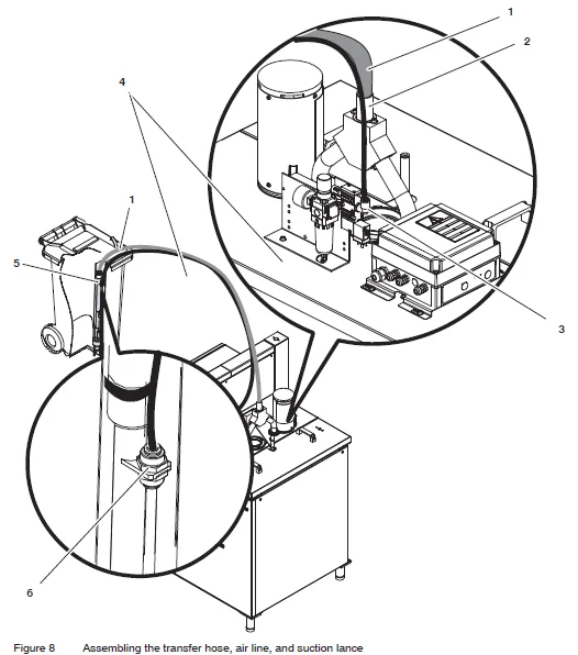
- Transfer hose
- Feed system inlet tube
- Solenoid valve air outlet
- Airline
- Suction lance
- Suction lance air inlet
Level Sensor Adjustment and Calibration
The level sensor consists of a level probe and a control box. The level probe permanently connects to the control box by a wire. The level probe has a black line around its diameter near the tip to note the maintained adhesive level. You can raise or lower the adhesive level by adjusting the level probe height.
NOTE: The level sensor should be recalibrated if the level probe height is changed or if the adhesive type is changed.
Adjusting the Level Probe Height
- See Figure 9. Remove the melter tank lid by loosening the two latch screws (1) and lifting it by its handles.
- Loosen the hex nut (2) on the level probe holder and slide the probe up or down as desired.
CAUTION! Do not raise the fill line of the probe above 50.8 mm (2 in.) from the bottom of the probe holder. Doing so will degrade the level sensor’s performance. - When the desired probe height is obtained, tighten the probe holder hex nut and reinstall the melter lid.
- Refer to the next procedure, Calibrating the Level Sensor, to calibrate the sensor.
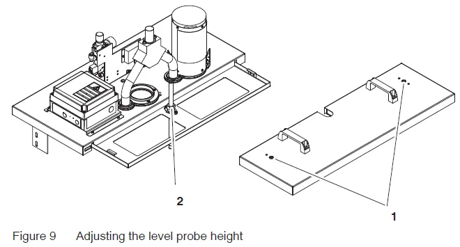
- Level probe holder hex nut
- Melter tank lid latch screws
Calibrating the Level Sensor
Recalibrate the level sensor if the level probe height is changed or if the adhesive type is changed.
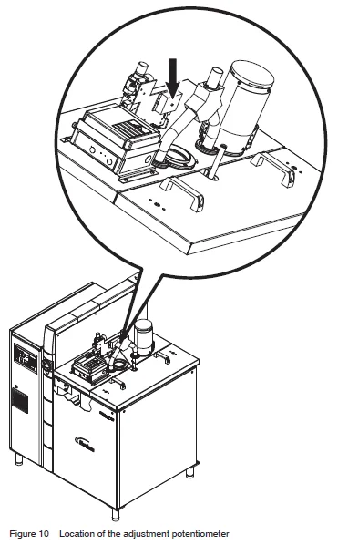
See Figure 10. The LED next to the adjustment potentiometer on the control box changes color from green to amber, depending on the adhesive level that the probe detects. When the adhesive drops below the desired level, the LED will turn green. When the adhesive reaches or exceeds the desired level, the LED will turn amber. The adjustment potentiometer sets the sensitivity of the level sensor. Different adhesives require different calibration settings. Adhesives that build up on the level probe require less sensitivity, while adhesives that do not build up on the level probe require more sensitivity.
Baseline Setting
- Remove the threaded plug on the front face of the level sensor control box to reveal the adjustment potentiometer.
- Fill the tank with adhesive up to the black line on the level probe. The adhesive does not have to be liquid.
- If the LED on the control box is amber, turn the adjustment potentiometer counter-clockwise until it turns green. If the LED on the control box is green, turn the adjustment potentiometer clockwise until it just turns amber. The point at which the LED transitions from green to amber is the switching point.
- Once the switching point is found, rotate the adjustment potentiometer 1/2 turn clockwise and leave it at that position.
- Reinstall the tank lid and tighten the latch screws.
Final Setting
- Begin normal operation. Check the adhesive level in the tank after 30 minutes of operation.
- If the adhesive level is satisfactory, the calibration procedure is complete. Reinstall the plug over the calibration pot to discourage tampering.
- If unmelted adhesive is piled up to the top of the tank or the system has already faulted due to overfilling, rotate the adjustment pot 1/2 turn clockwise to increase the level sensor’s sensitivity. Wait 10 minutes and check the adhesive level again. If the adhesive level is still too high, repeat this process until the adhesive level is satisfactory. When finished, reinstall the plug over the calibration potentiometer.
- If unmelted adhesive has built up on the probe and the adhesive level in the tank has dropped below the black line on the probe, rotate the adjustment potentiometer 1/2 turn counter-clockwise to decrease the level sensor’s sensitivity. If the adhesive level is still too low, repeat this process until the adhesive level is satisfactory.
Operation
Once enabled, the fill system immediately begins operation. Maintain the adhesive level in the storage bin to maintain automatic operation.
NOTE: During warm-up, the melter’s ready-delay time may need to be increased for the Fulfill unit to operate properly. The proper ready-delay time depends on the tank size and shape, adhesive type, and application temperature.
Time Settings
See Figure 11. There are three timers found on the refill board located inside the control box:
- Fault (overfill timer)—This timer is used to limit the amount of filling time in case of level sensor failure. It is only for overflow protection. The fault limit time is preset from the factory at 60 seconds, but can be adjusted from 5 to 115 seconds. The factory sets the potentiometer at the 12 o’clock position, which is sufficient for the majority of applications. For reference, the 9 o’clock position is 22 seconds, and the 3 o’clock position is 98 seconds.
- Delay—This timer is used to set the number of seconds that should elapse between the time the level sensor calls for more adhesive and the time the fill system activates. The delay time prevents the system from frequently turning on and off. The delay time is preset from the factory at 60 seconds, but can be adjusted from 0 to 119 seconds. The factory sets the potentiometer at the 12 o’clock position, which is sufficient for the majority of applications. For reference, the 9 o’clock position is 20 seconds, and the 3 o’clock position is 100 seconds.
- Air—This timer is used only with the optional storage bin vibrator kit. When installed, the vibrator will actuate for up to 20 seconds before the fill system activates and will stay on until the level sensor is satisfied. The air timer range is 0 to 20 seconds.
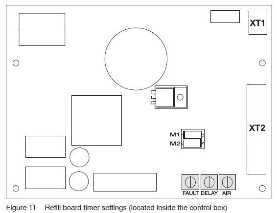
Use a flat head screwdriver to turn the timers clockwise to increase the time settings, counterclockwise to decrease the time settings.
Monitoring Refill Operation
See Figure 12.
Under normal conditions, the operator need not monitor or intervene in the operation of the fill system.
However, if the fill system is unable to satisfy the tank sensor within the time limit set for the Fill Time, the Fault LED will illuminate. Refer to Troubleshooting for a list of possible fault causes and solutions.
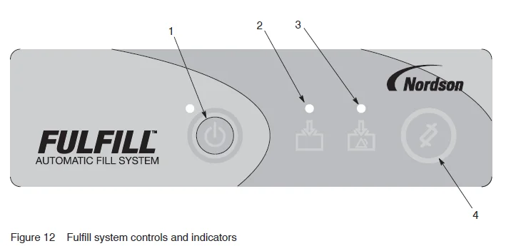
- Enable the On/Off key and the LED (green)
- Adhesive transfer LED (blue)
- Fault LED (red)
- Clear Fault key
Maintenance
Inspect the system daily to ensure that hose fittings are secure and that the unit is free from dirt and debris. Inspect the filter sock weekly to ensure that it’s not clogged; replace as needed.
Troubleshooting
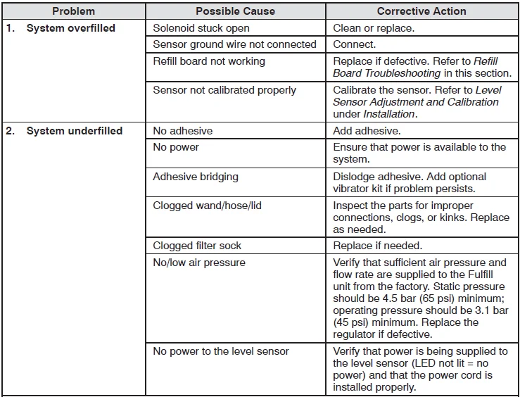
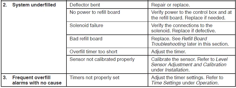
If the fill system fails and the condition cannot be corrected, to continue operating the melter (and filling it manually), disable the fill system (ensure that the fill system Enable On/Off LED is not illuminated).
Troubleshooting Table
Refill Board Troubleshooting
Perform the following steps in order to either isolate the problem within the refill board or to eliminate the refill board as a cause. These tests should only be performed by personnel qualified to work on high-voltage circuits.
- Verify input power is reaching the refill board. Measure the line voltage across the input side (side of the fuse closest to the input connectors J1 and J2) of fuses F1 and F2. The input voltage should be between 100−240 VAC. If the input voltage is not present, correct the input power.
- Verify that the 24 VDC power supply on the refill board is working by measuring the voltage between XT1 pin “24V” and XT1 pin “COM.” It should be 24 VDC (+/− 5%). If it is not 24 VDC, verify that the fuses are not blown. If fuses have been blown, replace the fuses. If any fuses blow again, replace the refill board. If the fuses are okay but 24 VDC is not present, replace the refill board.
- Ensure that the DIP switch settings have not been changed. SW1 DIP switch settings: M1 should be OFF; M2 should be ON.
- Make sure the timer potentiometers are set as expected:
- FAULT potentiometer adjustment range: 5 to 115 seconds (60 seconds at 12:00 position),
- DELAY potentiometer adjustment range: 1 to 119 seconds (60 seconds at 12:00 position),
- AIR (optional pre-vibrator) potentiometer adjustment range: 0 to 20 seconds (10 seconds at 12:00 position).
- Make sure the refill board is enabled by verifying that the “ENA” LED close to the membrane panel connector (X1) is illuminated. If not, press the Enable On/Off key on the membrane panel to enable the refill board. If the “ENA” LED does not turn on with the membrane panel, the membrane panel or refill board may be bad. With a piece of wire, briefly touch X1 pin 1 to X1 pin 2 (the membrane tail will need to be unplugged to perform this test). If the “ENA” LED illuminates after this test, replace the membrane panel. If not, then replace the refill board.
- To ensure that the level sensor signal is getting to the refill board with the level sensor calling for adhesive, verify that there is 24 VDC (+/− 5%) between XT1 pin “SIG” and XT1 pin “COM.” If not, repair the level sensor cable, recalibrate the level sensor, or replace the level sensor.
- To ensure that the refill board fill output is working correctly with the level sensor calling for adhesive and after waiting the DELAY time duration, verify that 24 VDC (+/−5%) is applied to the fill control output (XT2 pin “FILL” measured to any “COM” pin). Verify that the level sensor is NOT calling for adhesive that the fill control output is 0 to 0.5V.
If the problem has not been isolated at this point, replace the refill board and/or membrane panel.
Technical Data
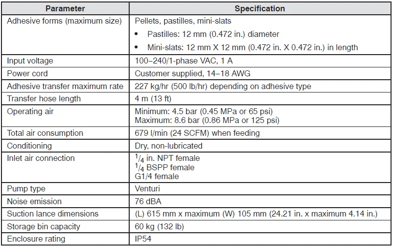
Specifications
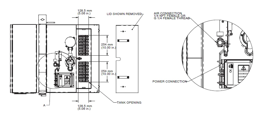
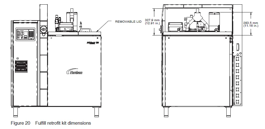
Dimensions
For more manuals by Nordson, visit ManualsLibraryy
Nordson Fulfill Retrofit Adhesive Fill Kit- FAQs
What is the Nordson Fulfill Retrofit Adhesive Fill Kit used for?
It is designed to automatically refill adhesive tanks, reducing manual handling and maintaining consistent production flow.
How does the retrofit adhesive fill system work?
The system monitors adhesive levels and automatically adds hot melt when needed, helping avoid downtime and char buildup.
Can the kit be installed on existing Nordson melters?
Yes, it is built as a retrofit solution and can be added to compatible Nordson melters without major modifications.
What are the main benefits of using this kit?
It improves safety by reducing operator contact with hot melt, ensures continuous operation, and extends equipment life.
How is the adhesive supplied to the melter?
The kit connects to adhesive supply containers and delivers material directly into the melter tank automatically.
What maintenance does the system require?
Routine checks include cleaning the fill sensor, inspecting hoses, and ensuring adhesive supply containers are sealed and dry.
What should I do if the system is not filling properly?
Check for blocked hoses, verify the adhesive supply level, and inspect the sensor for contamination. Reset if required.
Is special training required to operate the Fulfill kit?
Basic training is recommended, but the system is designed for simple operation once installed and connected properly.

