Nordson Iso-Flo Automatic Voltage Blocking System
Description
Introduction
WARNING: Operating the system with more than one spray device connected to it may be unsafe and in violation of National Fire Prevention Association (NFPA) regulations. It also voids the warranty. If this occurs, Nordson Corporation will not be responsible for the performance or life of the system.
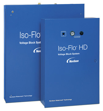
The manual Iso-Flo HD voltage block system is used with electrostatic waterborne coating systems equipped with low-pressure spray devices. The Iso-Flo system delivers pressurized coating material on demand without the use of electricity or external controls. In addition, it electrically isolates the charged spray device and fluid path from the grounded coating material supply.
Description
The manual Iso-Flo HD voltage block system is installed between the coating material kitchen or supply pump, and the spray device. This permits charged coating material to flow to the spray device but prevents voltage from grounding at the kitchen or pump. You can mount the system on a wall, free-standing panel, or dolly. Coating material can be charged at the spray device or at the Iso-Flo HD system in the following ways:
- at the spray device, with voltage supplied by an internal power supply (integral power supply (IPS)) or by an external power supply through a cable to the spray device
- at the Iso-Flo HD system, with voltage supplied by an external power supply through a cable to the Iso-Flo system
System Components
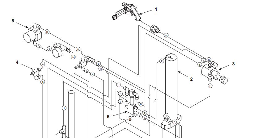
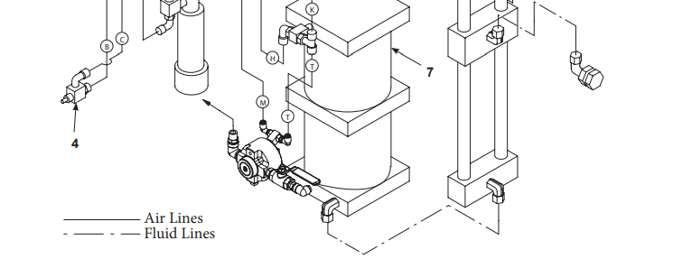
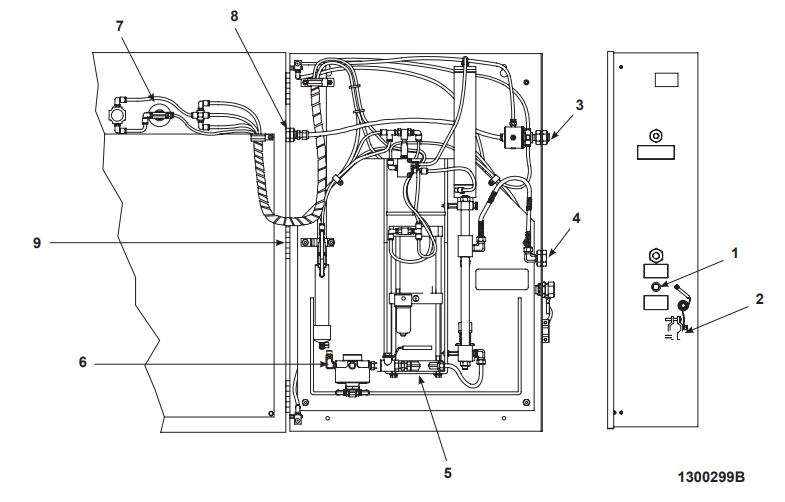
The Iso-Flo system consists of a pneumatically operated shuttle, pump, valves, and interconnecting lines. Figure 2-1 illustrates the components.
Figure 2-1 Internal View
- Door interlock valves
- Flow sensor
- Compressed air fitting: 1/4 in. NPT
- Paint inlet: 3/8-in. NPT
- Ground strap and clamp
- Male coupling
- Female coupling
- Pump
- Arc suppressor
- Paint outlet: 3/8-in. NPS
- Atomizing air outlet: 1/4-in. NPT
- Fluid pressure regulator
- Air gauge
- Toggle valve
- Shuttle valve
- Shuttle
Component Functions
Before using the Iso-Flo HD system, you should understand how the components work. Table 2-1 lists each component and describes its function.

System Operation
See Figure 2-2. When you trigger the spray device, the shuttle (16) opens and breaks the connection to the coating material supply. The pump (8) pressurizes the coating material and delivers it to the spray device. The coating material is electrostatically charged only from the shuttle to the spray device.
When you release the trigger on the spray device, the shuttle closes and grounds the fluid path. Coating material flows through the shuttle couplings (6, 7) to refill the pump. To prevent electrical shock, the door interlock valves (1) close the shuttle and ground the fluid path if the cabinet door is opened while you are spraying coating material.
Start Spraying
Figure 2-2 illustrates the flow of air and coating material through the system. The following steps describe what happens when you start spraying.
- Squeezing the trigger on the spray device (1) starts the flow of coating material and atomizing air.
- The flow sensor (3) detects the flow of atomizing air and sends a separate air signal to the door interlock valves (4). If the cabinet door is closed, the air signal from the flow sensor passes through the door interlock valves to the pilot valve (6) in the shuttle valve assembly.
- The pilot valve switches and causes compressed air from the atomizing air source to pass through the shuttle valve, enter the coating material shuttle cylinder (2), and force the shuttle up to the open position.
- The compressed air also operates the air motor to pressurize and deliver the coating material to the spray device.
Stop Spraying
When you release the trigger, the spray device will continue to spray until the time delay expires and the flow sensor stops sending air to the door interlock valves. This relieves pressure to the pilot on the pilot valve and switches it to the normal position.
- In the normal position, compressed air passes to the bottom of the shuttle cylinder and causes the shuttle to close.
- While the shuttle is closed, the coating material passes through the shuttle and refills the pump.
- The next time the trigger is squeezed (whether the pump is completely refilled or not), the sequence repeats.


- Spray device
- Coating material shuttle
- Flow sensor
- Door interlock valves
- Pressure regulator
- Pilot valve
- Pump air motor
Door Interlock Valve Operation
The door interlock valves (4) shut the system down if the door is opened. When the door is opened, the door interlock valves exhaust the pilot valve (6), which closes the coating material shuttle (2) and grounds the system.
Specifications and Operating Requirements
Special Conditions for Safe Use
The installation, operation, maintenance, and repair of the system equipment shall be in accordance with the Safety Instructions and the User’s Manual supplied by the Manufacturer. The power supply/control unit type XPS 60 and the Iso-Flo unit shall be installed only in a safe area.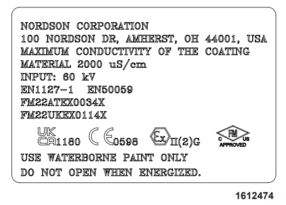
European Union Standard 50059; Section 6.2.1 and 6.2.2 (Electrostatic hand-held spraying equipment – Safety requirements – Hand-held spraying equipment for non-ignitable coating materials)
Waterborne Equipment Safety info:
- Electrostatic hand-held spraying equipment shall only be used with non-ignitable liquid coating material with a conductivity of less than 2000 µS/cm;
- Electrostatic hand-held spraying equipment shall only operate with direct current having a sinusoidal ripple of not more than 10 % of the rms value.
- Electrostatic hand-held spraying equipment shall only be operated by competent persons.
- Protective clothing to be worn, including gloves, shall comply with EN 1149-5. The measured insulation resistance shall not exceed 100 MΩ;
- Electrostatic hand-held spraying equipment shall be used only in spraying areas according to EN 12215, or under equivalent ventilation conditions.
- Electrostatic hand-held spraying equipment shall be interlocked with the forced ventilation.
- All conductive components of the system, like for instance floors, walls, ceilings, protective gratings, transport devices, workpieces, reciprocators, or constructional parts, etc., within the spraying area, except for parts that are at high voltage for operational reasons, shall be connected to the earthing system. Parts of the booth shall be earthed in accordance with EN 12215.
- Electrostatic hand-held spraying equipment shall only be operated in a safe and sound manner.
Damaged equipment shall be put out of operation immediately and shall be replaced or repaired.
- spare parts can have safety-relevant properties;
- Only original spare parts shall be used, which are also subject to a quality assessment (e.g., production control);
- worn parts shall be replaced immediately;
- Only electrically conducting containers shall be used for cleaning liquids; the containers shall be earthed.
- Non-ignitable cleaning agents shall be preferred.
- appropriate measures shall ensure that the resistance to earth of the jig shall not exceed 1 MΩ, measured at 500 V or 1 000 V.
- all references required for a correct operation of the equipment;
- mode of functioning of the safety devices;
- measures in case of disturbances and repairs;
- This electrostatic hand-held spraying equipment could present hazards if it is not operated according to the information given in the instruction manual.
- Footwear to be worn by the operator shall comply with EN ISO 20344. The measured insulation resistance shall not exceed 100 MΩ;
- It shall be ensured that excess coating material (overspray) will be collected reliably.
Test Intervals of Repeated Tests
Installation
Introduction
Installation procedures vary, depending on the following factors:
- where the coating material is charged, either
- inside the unit, or
- at the gun
- how the power supply is controlled, if coating material is charged inside the unit, either
- with a pressure switch activated by the air signal from the flow sensor, or
- with a flow switch in the atomizing air line
- how atomizing air pressure is regulated, either
- at the spray device, or
- with a separate regulator installed outside the cabinet
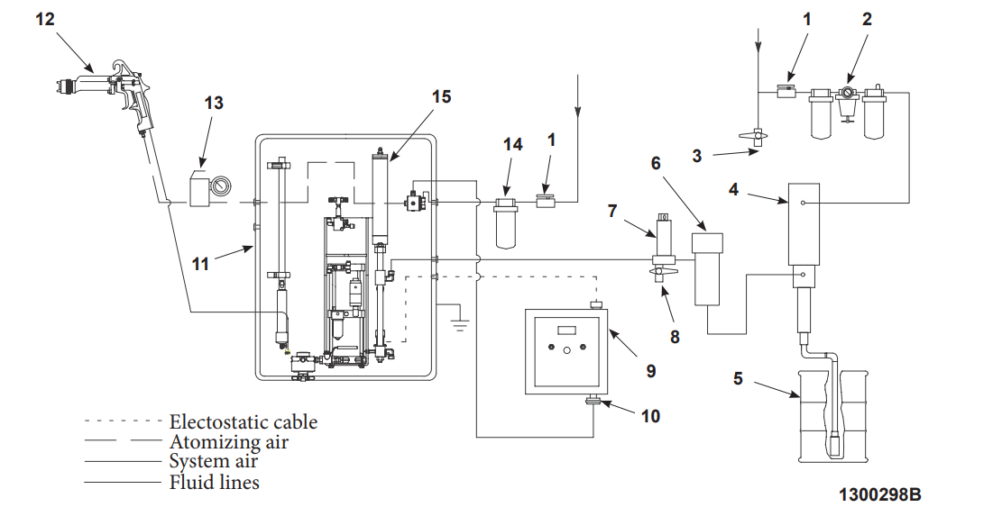
- Figure 3-1 shows the installation of a typical waterborne air spray system.
Remove the packing foam insert located behind the shuttle (15) after the system is mounted upright.
- Main air shutoff valves
- Filter/regulator/lubricator assembly
- Airline drip-leg valve
- Drain valve
- Coating material supply
- Coating material heater (optional)
- Fluid filter
- Fluid filter drain valve
- Electrostatic power supply
- Pressure or flow switch (can be installed on the power supply)
- Iso-Flo HD System
- Air spray device
- Atomizing air regulator
- Air filter
- Shuttle

Mounting
Locate the manual Iso-Flo HD voltage block system between the coating material kitchen, or the pump and the spray device. This allows charged coating material to flow to the spray device, but prevents voltage from grounding at the kitchen or the pump.
- Mount the unit inside or near the spray booth, or on a dolly so the coating material hose connecting the Iso-Flo HD system and the spray device is as short as possible. Use four 1/4-in. fasteners.
- See Figure 3-2. Clip the ground strap (2) to a true earth ground.

Figure 3-2 Connection Points
- Electrostatic CABLE port
- Ground strap
- COMPRESSED AIR fitting (1/4-in. NPT)
- PAINT INLET (3/8-in. NPT)
- Pump
- PAINT OUTLET (3/8-in. NPS)
- Air gauge
- ATOMIZING AIR OUT (1/4-in. NPT)
- Grommet (fluid hose to spray device)
Fluid, Air, and Electrical Connections
See Figure 3-2. Make all fluid, air, and electrical connections through the fittings and holes in the sides of the cabinet. WARNING: To prevent electrical shock and to retain FM approval, use the recommended types of fluid hoses. Make sure you use:
- a fluid hose that has protective, durable, or reinforced insulation
- an air hose with a conductive outer braid, which is grounded where it connects to the Iso-Flo HD system and the handle of the spray device
Fluid, Air, and Electrical Connections (contd)
- Connect the coating material supply hose to the 3/8-in. NPT fitting labeled PAINT INLET (4).
- Connect the air supply hose to the 1/4-in. NPT air inlet fitting labeled COMPRESSED AIR (3). The hose should have metal fittings on each end. Continuity must exist between the fittings, and the hose must be grounded.
- Connect the spray device fluid hose to the 3/8-in. NPS fitting at the pump outlet (6). Route the hose through the grommet on the left side of the cabinet labeled PAINT OUTLET. Refer to your spray device manual for more information.
- Connect the spray device atomizing air hose to the 1/4-in. NPT fitting on the left side of the cabinet labeled ATOMIZING AIR OUT (8).
- Use the 1/4-in. screw or an appropriate cable adapter to attach the end of the electrostatic cable to the shuttle through the CABLE port (1).
Atomizing Air Pressure Regulator
See Figure 3-2. If your air spray device does not have an atomizing air pressure regulator, install a compact regulator in the atomizing air line ahead of the spray device.
- Disconnect the atomizing air hose from the 1/4-in. NPT fitting labeled ATOMIZING AIR OUT (8).
- Attach the regulator to the atomizing air outlet.
- Connect the atomizing air hose to the regulator.
Operation
Preparation
On initial startup of the Iso-Flo HD system, add 1/2 ounce of properly diluted Q-solvent to the lubrication cup on the pump. Mix the Q-solvent according to the instructions provided on the container label.
System Flush
Perform a system flush before you use a new system, when you change coating material, or to clean the system. Use a cleaning solution compatible with the system equipment and coating material you will be using.
Flushing a New System
Performing a system flush on a new Iso-Flo HD system will remove oils, metal filings, and other contaminants left from the manufacturing and installation process.
WARNING: Risk of electrical shock. Turn off the electrostatic voltage before opening the cabinet door. Failure to observe this warning could result in personal injury, death, or equipment damage.
WARNING: Make sure the room where you are working is sufficiently ventilated during the flushing procedure. Avoid breathing vapors over prolonged periods of time.
Flushing a New System (contd)
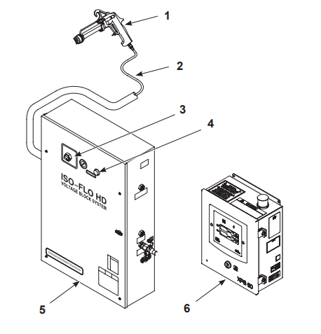
- Shut off the electrostatic power supply (6).
- Disconnect the fluid hose (2) at the spray device (1). Secure the end of the hose in a waste container.
- Turn on the compressed air to the system.
- Turn the fluid pressure adjustment knob (4) to the maximum setting of 10.3 bar (150 psi).
- Supply cleaning solution to the Iso-Flo system (5).
- Move the toggle valve (3) to the empty position and hold it there.
- Continue to hold the toggle valve in the empty position until the cleaning solution runs clear. Release the toggle valve.
- Reconnect the fluid hose to the spray device and repeat step 7.
- Flush the Iso-Flo system until the cleaning solution runs clear.
- Fill the system with coating material.
- Set the atomizing air pressure and the fluid output pressure to the normal operating settings.
Changing Coating Material or Cleaning the System
- Turn off the electrostatic power supply (6) and the atomizing air.
- Reduce the fluid-input supply pressure to 0.
- Switch the toggle valve (3) to the empty position.
- Trigger the spray device (1) into the spray booth or into a grounded waste container to expel any remaining coating material.
- Supply cleaning solution to the Iso-Flo system (5).
- Trigger the spray device into the spray booth or into a grounded waste container. This flushes the system pump, hose, and spray device.
- Flush the system until the cleaning solution runs clear. Continue flushing the system until the cleaning solution and any remaining air have been purged from the system.
- Turn off the cleaning solution and introduce a new color coating material. Repeat steps 4 and 5 until the coating material purges all remaining cleaning solution from the system.
- Release the toggle valve and the spray device trigger. The new coating material will fill the system.
- Set the atomizing air pressure and fluid input pressure to the normal operating settings.
- Turn on the power supply and start applying the new coating material.

- Spray device
- Fluid hose
- Toggle valve
- Fluid pressure adjustment knob
- Iso-Flo HD system
- Electrostatic power supply
Daily Operation
Startup and shutdown procedures can vary depending on your safety regulations and system requirements. If the solids will not settle out or the coating material will not cure in the system, you can leave your system full of coating material overnight.
Startup
WARNING: Ground all electrically conductive equipment in the spray area. Check the Iso-Flo cabinet ground. Make sure all internal and external connections are clean and secure. Ungrounded conductive equipment can store a static charge, which could ignite a fire or cause an explosion if a hot spark is discharged. The following procedure assumes the system was left full of coating material after the last shutdown.
- Make sure the electrostatic voltage is off.
- Turn on the compressed air to the Iso-Flo system (5).
- Set fluid inlet pressure to a maximum setting of 10.3 bar (150 psi) with the fluid pressure adjustment knob (4).
- Turn on the electrostatic power supply (6) or the spray-device control system.
- Begin spraying.
The Iso-Flo system is always ready for spraying, even if the pause in production is not long enough to allow the pump to refill completely.
NOTE: Shut off the electrostatic voltage during short breaks in production, but leave the air supply on. This keeps the shuttle closed and prevents coating material from drying on the couplings.
Fluid Pressure Adjustments
- Turn the fluid pressure adjustment knob (4) to make a small adjustment to the fluid pressure.
- Squeeze the trigger on the spray device (1).
Atomizing Air Adjustments
Use an external air regulator to adjust the atomizing air. Continue to adjust the air regulator until you achieve the required atomization.
Short-Term Shutdown
- Shut off the electrostatic power supply.
- Shut off compressed air to the system. Reduce the fluid input and coating material supply pump pressure to 0.
- Trigger the spray device to relieve fluid and compressed air pressure.
- Open the cabinet door and separate the couplings to manually lower the shuttle.
- Clean the male and female couplings with a compatible cleaning solution.
- Close the cabinet door.
Long-Term Shutdown
- Turn off the electrostatic voltage.
- Flush the system with a compatible cleaning solution using steps 1–8 in Changing Coating Material or Cleaning the System on pages 4-2.
- Relieve the compressed air pressure. Drain the system completely.
- Open the cabinet door. Separate the couplings to manually lower the shuttle.
- Clean the male and female couplings, the exterior of all cabinet components, and the cabinet with a compatible cleaning solution.
- Close the cabinet door.
Maintenance
The manual Iso-Flo HD voltage block system requires minimal routine maintenance. Maintenance points are shown in Figure 2-1. To keep the system operating at its maximum efficiency, use the following procedures.
Daily
- Shut off the electrostatic voltage to the system.
- Shut off compressed air to the system.
- Shut off the fluid supply to the system.
- Squeeze the trigger on the spray device to relieve compressed air pressure.
- Open the cabinet door. Move the shuttle to manually separate the couplings.
- Clean the male and female couplings with a compatible cleaning solution to prevent coating material buildup.
- Apply a small amount of compatible lubricant to both couplings. This will keep the coating material from sticking and will facilitate cleanup.
- Close the cabinet door.
Weekly
- Shut off the electrostatic voltage to the system.
- Shut off compressed air to the system.
- Shut off the fluid supply to the system.
- Squeeze the trigger on the spray device to relieve compressed air pressure.
- Flush the system with a compatible cleaning solution, as needed, following steps 1–5 in the Changing Coating Material or Cleaning the System section on page 4-2.
- Open the cabinet door. Move the shuttle to manually separate the couplings.
- Clean the male and female couplings with a compatible cleaning solution. Lightly coat the female coupling shafts with O-ring grease. Use a stiff brush to work the grease through the spring.
- The lubrication cup is located on the front of the pump. Unscrew the plug on the top of the lubrication cup and add ½ ounce of properly diluted Q-solvent to the cup.
- If your Iso-Flo unit is not equipped with an air lubricator, remove the air supply hose and add 5–10 drops of lightweight valve oil into the ¼-in. NPT fitting labeled COMPRESSED AIR on the side of the unit.
- Close the cabinet door.
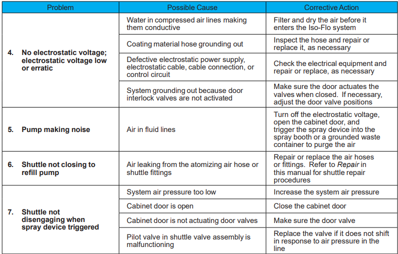
Troubleshooting
WARNING: Allow only qualified personnel to perform the following tasks. Follow the safety instructions in this document and all other related documentation.
WARNING: Turn off the electrostatic voltage before opening the Iso-Flo cabinet door. Failure to observe this warning could result in personal injury or death.
NOTE: This section contains troubleshooting procedures. These procedures cover only the most common problems that you may encounter. If you cannot solve the problem with the information given here, contact your local Nordson representative for help.

For More Manuals By Nordson, Visit ManualsLibraryy.


