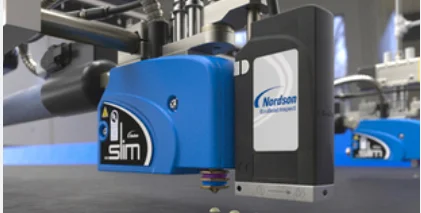
Nordson OptiStroke Needle Stroke Detection System
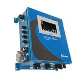
What is OptiStroke?
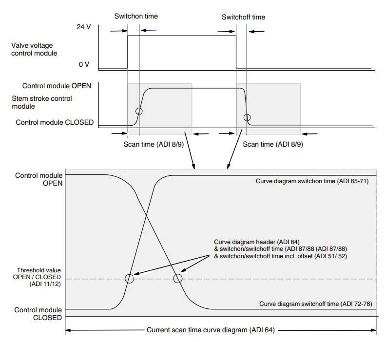
OptiStroke is an electronic device that monitors and displays the opening and closing times of control modules on Nordson applicators. The measurements are evaluated, and an alarm is triggered if the nozzle stem in a control module does not move at all or moves outside the previously set time range. The alarm signal No stem stroke can be used for product ejection purposes. Curve diagrams of the stem stroke triggered by the valve signal can be used for analysis purposes (example: Figure 2).
System Environment
Function
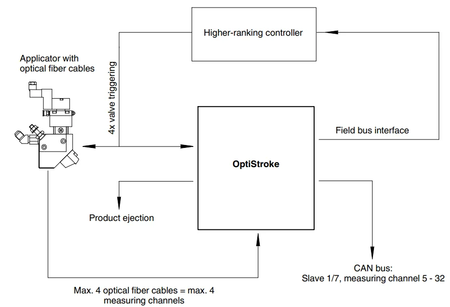
OptiStroke works in conjunction with an applicator. Optical fiber cables are connected to the applicator control module. The optical fiber cables capture the movement of the nozzle stems triggered by the valves and transmit it to OptiStroke as an optical signal. Each control module is connected to exactly one measuring channel in the OptiStroke. OptiStroke converts the optical signals to digital signals (switching times [ms]). This data is made available via the field bus interface for further
processing by a higher-ranking controller, and can be used to form a control circuit.
Field Bus Data Interface
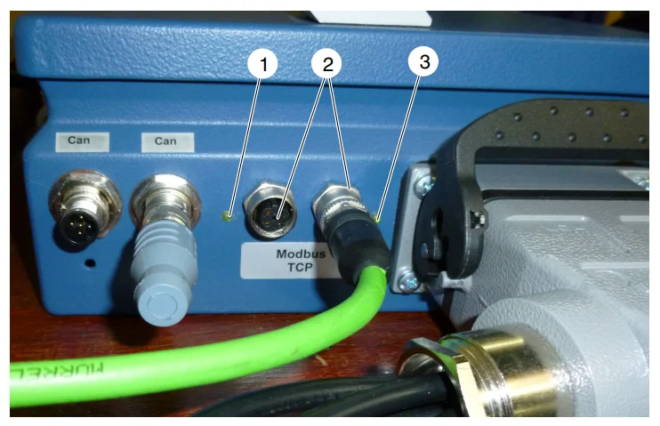
- LED 1 (network status)
- Field bus data interfaces
- LED 2 (module status)
The following sections describe the meaning of the LED colors and displays for the various field buses. OptiStroke has a field bus data interface (2, Fig. 3) that it uses for communication with a higher-ranking controller. The device is connected to one of the two receptacles. Nordson currently supports the following interfaces:
- Modbus TCP
- EtherNet/IP
Alarm Outputs
Several alarm outputs ensure continuous detection of defective control modules. Real-time product ejection is also possible when the application pattern is faulty.
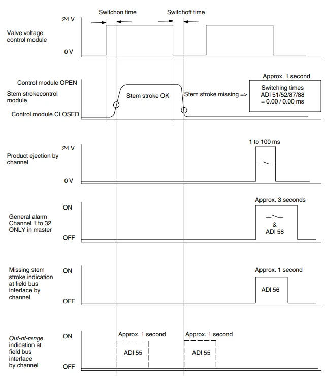
- Eject alarm (duration: default 50 ms). This error indication (voltage pulse) by channel can be used to activate a mechanism for product ejection.
- General alarm for all triggered measuring channels (duration: approx. 3 seconds). Measuring channels are triggered during initialization.
Hardware Alarms Master Box
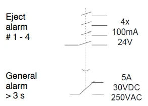
The general alarm and the ejection alarm can be queried at a relay in the OptiStroke master box.
- General alarm for all channels 1 to 32
- Eject alarm for all channels 1 to 4
Hardware Alarms Slave Boxes
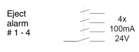
Only the eject alarms can be queried in the slave boxes.
- Eject alarm for all channels 1 to 4
Software Alarms via Interface
- Switching times for each channel (ADI 87 and 88)
- Switching times with offset for each channel (ADI 51 and 52)
- Missing stem stroke for each channel (ADI 56)
- Switching times are outside of the defined range (ADI 55)
OptiStroke measures and reports the control module switching times. Switching times of 0.00 / 0.00 ms are considered missing stem stroke.
Function Diagram – Alarms
Installation
Setting DIP Switches
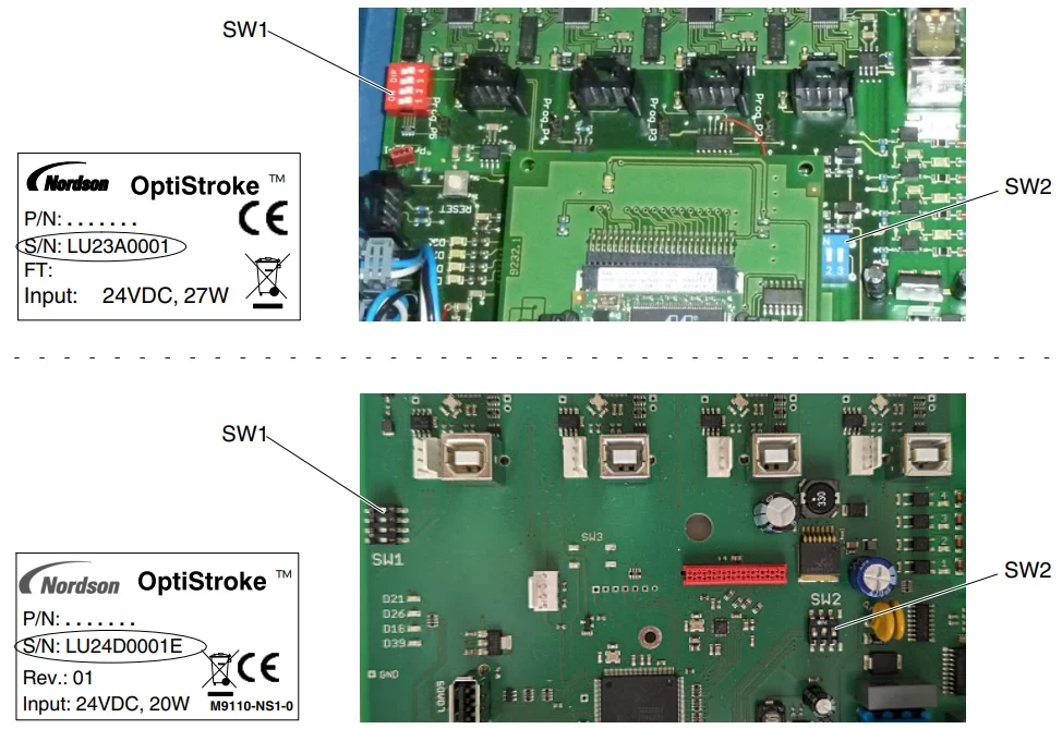
The DIP switches determine which control modules are connected to the individual channels and which OptiStroke boxes are included in the master-slave configuration.
Connecting Master and Slave with CAN Bus
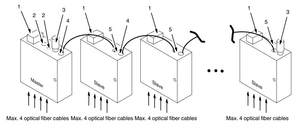
- HAN receptacle
- Field bus interface
- Terminating resistor
- CAN 2
- CAN 1
- Use a CAN bus cable to connect output CAN 2 on the master box to input CAN 1 on the slave box.
- Attach a terminating resistor to input CAN 1 on the master box.
- Use a CAN bus cable to connect output CAN 2 on the slave to input CAN 1 of the next slave.
- Attach a terminating resistor to output CAN 2 on the last slave.
Electrical Connection
The OptiStroke is delivered ready to be connected. All connections are made with plugs. Plugs and receptacles are physically keyed.
Connecting Higher-ranking Controller
Connect OptiStroke to a higher-ranking controller. This can be the Nordson VersaBlue melter or a PLC.
Operating Voltage
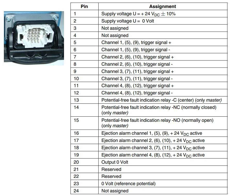
Operating voltage (24 VDC) is supplied via the HAN 24 plug.
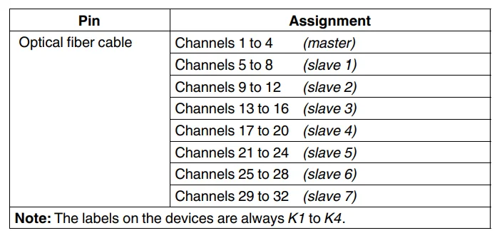
Optical Fiber Cable Channels
Pin Assignment of HAN Receptacle
Changing OptiStroke IP Address (Serial Number without E)
- Use the address configuration software HMS-IP Config from the included CD/DVD.
- Connect the gateway to a PC or laptop with an Ethernet cable.
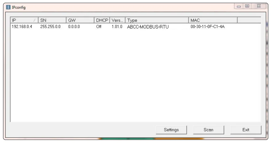
- Start the software HMS-IP Config. When it is started, the program automatically searches for any activated gateways; if not, press the Scan button

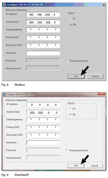
- (At least) One gateway appears in the scan list. Double-click the mouse to select. One of the following two windows appears:

- Set the desired IP configuration.
- Press Set to close the window.
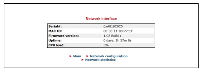
Checking and Changing OptiStroke EtherNet/IP Adapter Settings
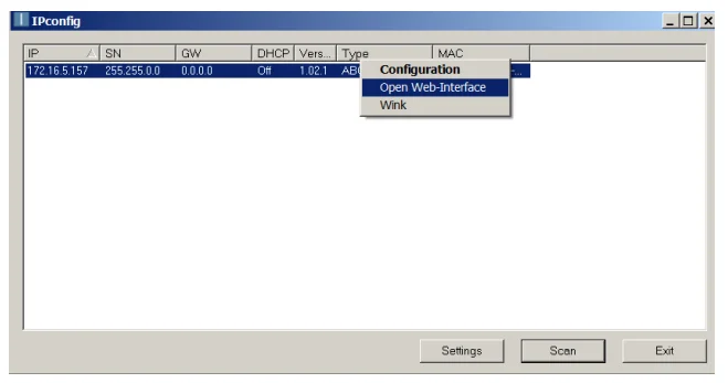
- Start the software HMS-IP Config.
- Select the OptiStroke found, then use the right mouse button to select Open Web-Interface.

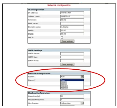
- Select Network configuration.

- Under Ethernet configuration (EtherNet Configuration), select AUTO for Comm 1 and Comm 2.

Resetting OptiStroke IP Address
If the current IP address of the OptiStroke box is unknown, it can be reset to 192.168.240.4.
- Start up the OptiStroke box.
- Connect the OptiStroke box to a PC/laptop.
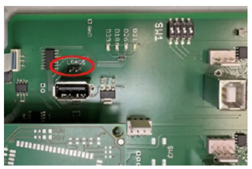
- Open the OptiStroke box.
- Use an appropriate tool to short-circuit the two LOAD 5-pin headers for five seconds

- Enter a new IP address of your choosing using the configuration software Modbus-IP Config-E. Refer to Setting Current OptiStroke IP Address.
Addition or Modification of Control Modules
If OptiStroke is to be used, and the control modules are not yet equipped with a threaded bore for optical fiber cables, add either suitable control modules or module caps to the existing control modules.
Connecting Optical Fiber Cables
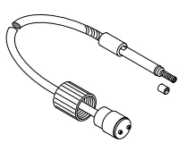
The optical fiber cables provide the optical connection between the control modules on the applicator and the OptiStroke.
- Wipe the end of the optical fiber cable with a clean, lint-free cloth.
- Screw the optical fiber cable (sensor) into the corresponding control module or into the module cap on the corresponding control module.
- Connect the other end of the optical fiber cable to the corresponding receptacle on the OptiStroke box and secure with the sleeve nut.
Operation
- Switch on the customer’s 24 VDC voltage supply via the receptacle HAN for OptiStroke.
- Verify that the system environment (controller, melter, heated hoses, applicator) is ready.
- Start material application.
- Switch off when production is finished.
Maintenance
OptiStroke: OptiStroke requires no maintenance. Optical fiber cable inputs not in use should be closed with suitable dust caps to keep them clean.
Optical Fiber Cable:
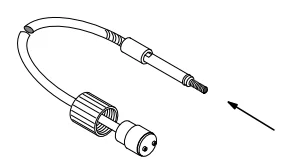
When replacing a control module and using the same optical fiber cable for the new module, wipe the end of the optical fiber cable with a clean, lint-free cloth.
Troubleshooting
Inside View
The OptiStroke box has to be opened to be able to see these LEDs. The two LEDs (5, Figures 13 and 14) are located on the field bus board.
OptiStroke Box (Serial Number without E)
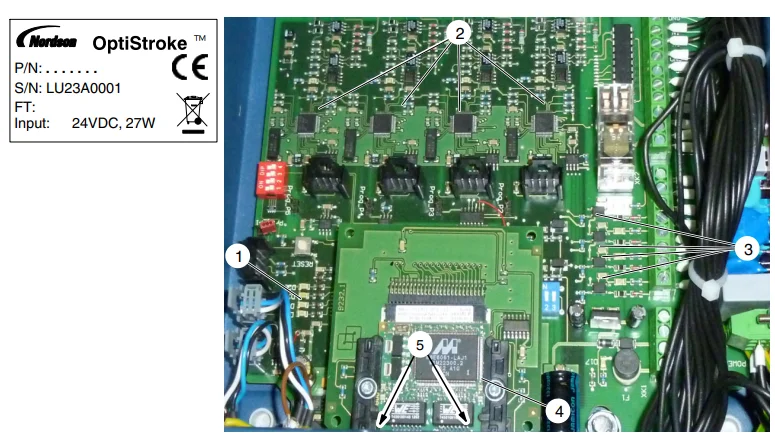
- Indicator beacon LEDs (D39, D18, D26, D21)
- Transmitted light LEDs (D22 to D25)
- Trigger LEDs (D27 to D30)
- Field bus module
- Link/Activity LEDs (not visible in the illustration)
Technical Data
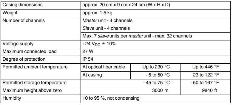
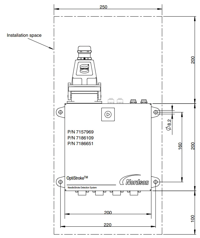
Casing Dimensions
OptiStroke with Mounting Tabs
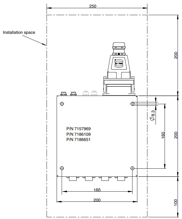
Drilled Holes on Back Panel
Modbus TCP
General Information
The Modbus TCP interface is used to centrally compile and process data. Data is exchanged between the customer’s machine and OptiStroke via ADIs (Application Data Instances).
Interface Features
- Data:
- Status information
- Alarms and errors
- Control signals
- Actual values
- Setpoints
- Limit parameters
- The byte sequence of the data in Word format is based on the Intel format (least significant byte first, 16-bit signed integer).
Interface
- Hardware: Field bus interface in the OptiStroke casing
- Classification: Slave
- Data transmission rate: 10 to 100 MBit/s
- Connection method: M 12, twisted pair line ‐ 10baseT-UTP, located at the gateway in the electrical cabinet
OptiStroke Address
Each unit on the Modbus needs its own IP address for communication purposes. Each address may be assigned only once in the entire network.
- Default of Modbus in OptiStroke. IP address 192.168.240.4
- Address setting. Refer to Installation – Changing OptiStroke IP Address earlier in this customer product manual
Installation
Connecting Modbus Line
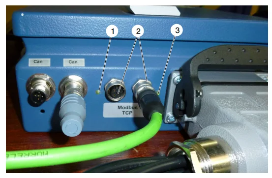
- LED 1 (network status)
- Field bus data interfaces
- LED 2 (module status)
- Connect the Modbus line to the network receptacle (2).
- Connect the free end of the Modbus line to the customer’s controller
Meaning of LEDs
LED 1 (1, Fig. 1) and LED 2 (3, Fig. 1) indicate the operating modes of the OptiStroke field bus data interface:
LED 1 – Network Status

LED 2 – Module Status

EtherNet/IP
General Information
The EtherNet/IP interface is used to quickly transmit cyclical I/O (input/output) data and acyclical parameter data (explicit messaging). EtherNet/IP was developed by Rockwell Automation and the ODVA (Open DeviceNet Vendor Association), and it was standardized according to IEC 61158. The CIP protocol (Common Industrial Protocol) is used as the application protocol. EtherNet/IP is based on the master/slave architecture. The customer’s control system must also have an Ethernet/IP master interface.
Connecting Ethernet Line
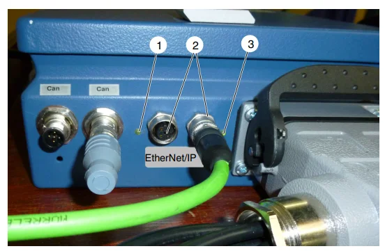
- LED 1 (network status)
- Field bus data interfaces
- LED 2 (module status)
- Connect the Ethernet line to the network receptacle (2).
- Connect the free end of the Ethernet line to the customer’s controller or the switches
Reading Files
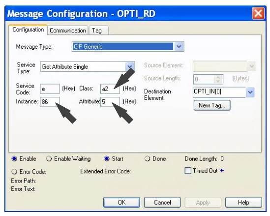
Data is read with the aid of the so-called Message commands. The following illustration shows the read (RD = Read) settings that have to be changed:
- Enter the value a2 for all parameters in the Class field.
- Enter the value 5 (Get/Set Value) in the Attribute field.
- Instance is an abbreviation of the Application Data Instances or ADIs shown here. They are explained later in this manual, in the Communication Data List.
Communication Data List and ADIs
The field bus interface is used to centrally compile and process data. The section Communication Data List applies to the field buses Modbus TCP and EtherNet/IP. The customer’s control system must have the respective interface. And the customer must have a programming environment that can process the data via the interface. Nordson cannot offer any information on how the OptiStroke data is processed, because it is different for each customer.
FOR MORE MANUALS BY NORDSON, VISIT MANUALSLIBRARYY
Nordson OptiStroke Needle Stroke Detection System-FAQs
Q1. What is the Nordson OptiStroke system used for?
It monitors needle movement in adhesive dispensing valves to ensure accurate stroke and consistent application.
Q2. How does the needle stroke detection work?
The system uses sensors to track the opening and closing of the valve needle, confirming each stroke in real time.
Q3. Why is needle stroke monitoring important?
It helps detect misfires, clogging, or incomplete dispensing, reducing downtime and improving product quality.
Q4. How do I connect the OptiStroke system to a controller?
Connect the sensor cable to the compatible Nordson controller input, then configure monitoring parameters as outlined in the manual.
Q5. What indicators are shown on the OptiStroke display?
The system shows status signals for needle movement, error alerts, and operational readiness.
Q6. What maintenance is required for OptiStroke sensors?
Keep sensors clean, check cable connections regularly, and replace worn or damaged components when needed.
Q7. Can the OptiStroke system detect partial strokes?
Yes. It can identify incomplete strokes, which helps prevent under-dispensing or irregular adhesive lines.
Q8. How do I troubleshoot common issues?
Check sensor alignment, verify cable connections, reset the system if needed, and consult error codes in the user manual.

