
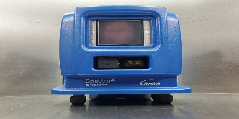
Nordson Spectra 30 Pattern Controller
Safety Label and Tag
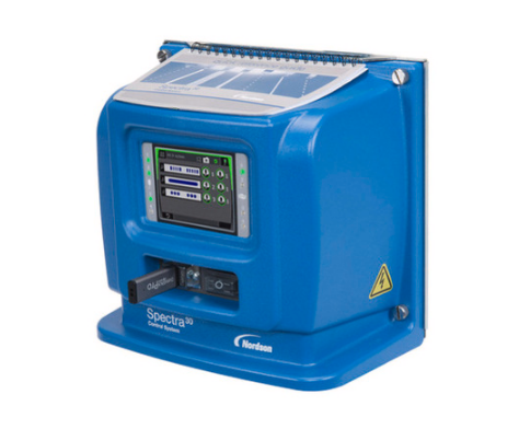
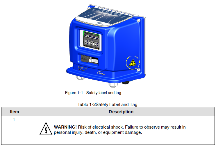
Figure 1‐1 illustrates the location of the product safety labels and tags affixed to the equipment. Table 1‐2 illustrates the hazard identification symbols that appear on each safety label and tag, the meaning of the symbol, or the exact wording of any safety message.
Overview
Getting to Know Spectra™ 30
The Spectra 30 pattern controller has the flexibility of having three configurations:
- Time‐based
The time-based functionality enables the pattern controller to monitor constant line speeds and has an accuracy of +/‐ 1 ms (1 mm at 60 m/min or 0.1 in. at 500 ft/min). - Distance (requires encoder)
The distance‐based functionality enables continuous tracking of line position to within one millimeter (or 0.1 inch). This allows dispensing of precise adhesive patterns at production speeds that reach 300 m/min (983 ft/min). Distance‐based systems can also operate in time-based systems. - Distance-based functionality with inputs/outputs, including two outputs which are proportional to the line speed (pressure run-up).
NOTE: The needed hardware exists in all the configurations. The functions are enabled by software licenses.
Spectra 30 Pattern Controller and Components
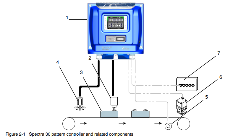
- Spectra 30 pattern controller
- Applicator
- Product
- Photocell
- Encoder (optional)
- Pressure run‐up transducer (optional)
- PLC interface (optional)
Standard Components
See Figure 2‐1 for the components that make up an integrated pattern control system. The standard components include:
- Spectra 30 pattern controller
- Up to four triggers
- Up to four applicators
Add‐on Software Licenses
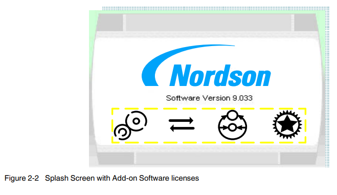
The time-based and distance and distance-based configurations can be upgraded through add-on software licenses, which provide the complete ability of the higher option(s). The software licenses can be ordered by specific part numbers. Refer to Parts for the software license part numbers.
For instructions on how to obtain add-on software licenses, refer to Appendix A, Using Add‐on Software Licenses.
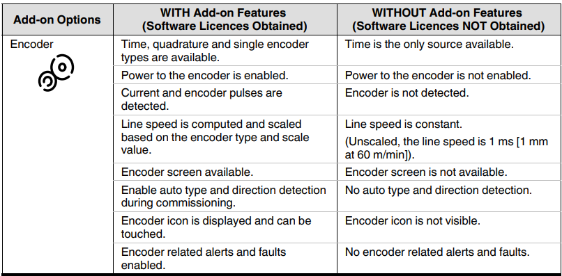
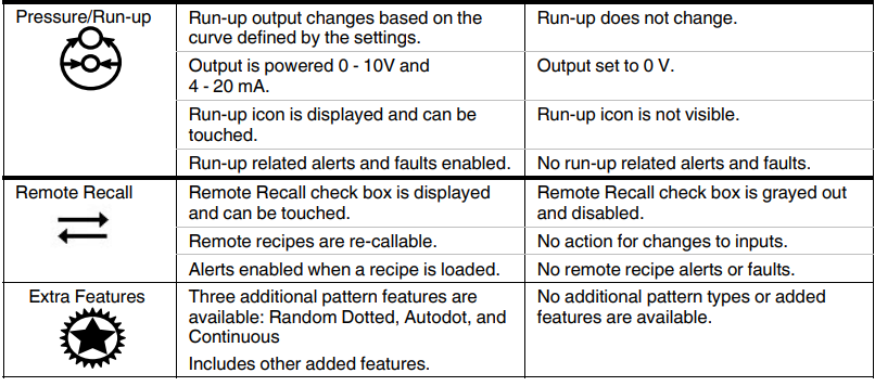
Comparison Table
The following table compares a pattern controller with or without the add‐on features.
Front Panel
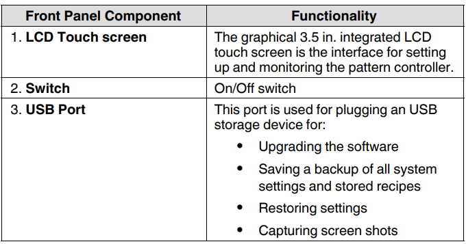
The front panel components are as follows:
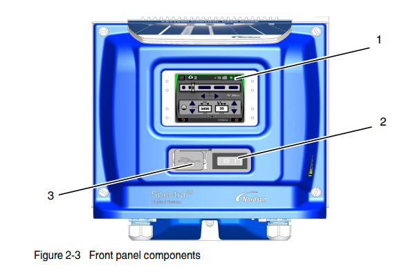
See Figure 2‐3 for the location of the following components.
Base Panel
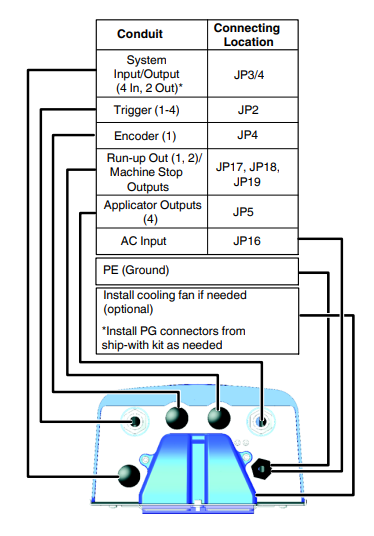
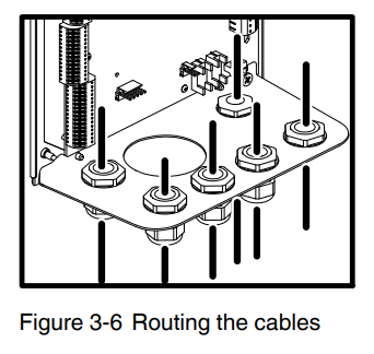
All the cables are routed through the conduits located on the base panel of the pattern controller.
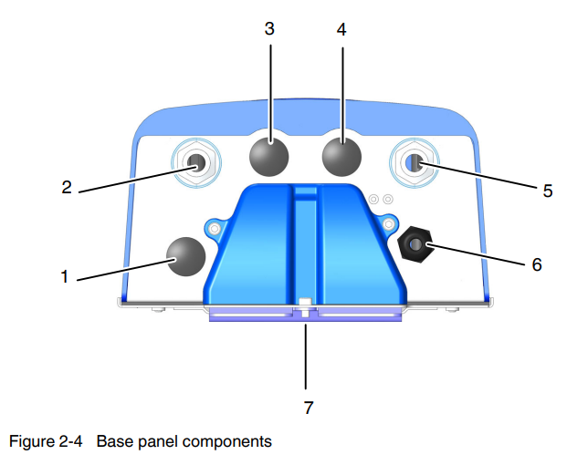
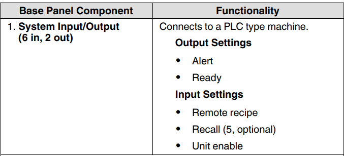
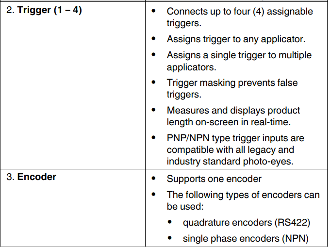
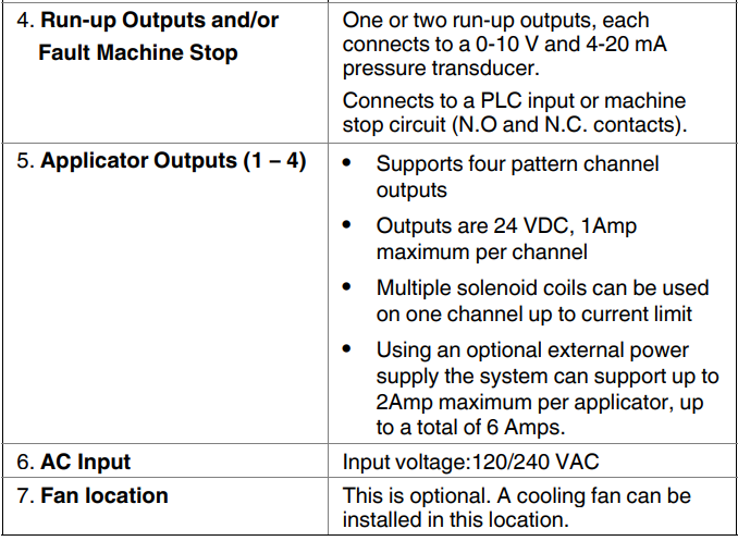
See Figure 2‐4 for the location of the following component.
Other Sources of Information
Refer to the following resources for getting the most out of your system components.
Quick Reference Guide
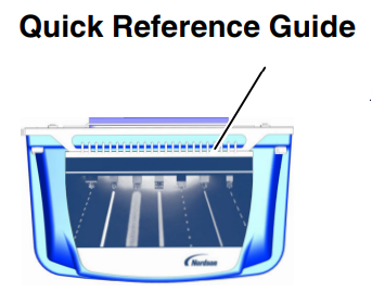
The Quick Reference Guide is affixed to the top panel of the pattern controller. It provides common setup and pattern generation tasks.
Installation Guide
The Installation Guide provides basic installation, connection, and initial system setup instructions.
Product Manual
Visit http://emanuals.nordson.com/adhesives to download the product manuals.
Software Update / Online Support
Visit www.enordson.com/support to view the training videos and to download updates and software utilities.
Using the Prism Utility
This PC utility is used for making advanced changes to the internal settings of the pattern controller. For more details, refer to Using the Prism Utility in Appendix B.
Download this utility from http://emanuals.nordson.com/adhesives/software.
Installation
![]() WARNING! Allow only personnel with appropriate training and experience to operate or service the equipment. The use of untrained or inexperienced personnel to operate or service the equipment can result in injury, including death, to themselves and others, and damage to the equipment.
WARNING! Allow only personnel with appropriate training and experience to operate or service the equipment. The use of untrained or inexperienced personnel to operate or service the equipment can result in injury, including death, to themselves and others, and damage to the equipment.
![]() WARNING! Allow only qualified personnel to perform the following tasks. Follow the safety instructions in this document and all other related documentation.
WARNING! Allow only qualified personnel to perform the following tasks. Follow the safety instructions in this document and all other related documentation.
Mounting the Spectra 30
Equipment and production line configuration may dictate a variation in the mounting options described in this section. Regardless of the mounting method used, refer to Guidelines.
Unpack the Pattern Controller
- Carefully unpack the pattern controller. Exercise care to prevent equipment damage during unpacking.
- Inspect for any damage that may have occurred during shipping. Report any damage to your Nordson representative.
Guidelines
- Position the pattern controller as close as possible to the parent machine or production line.
- Mount the pattern controller vertically on the wall or post.
- Ensure that the mounting location provides sufficient clearance around the bottom of the pattern controller to allow room for cable entry.
Dimensions
Use the following dimensions to mount the pattern controller.
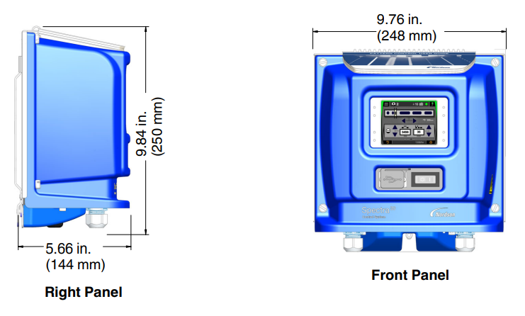
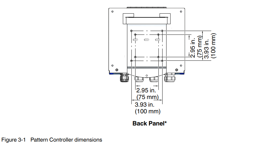
*NOTE: The back mounting plate has a standard VESA mounting pattern, which allows the use of off‐the‐shelf mounting accessories.
Mount the Pattern Controller
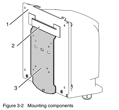
- Locate the following components required for mounting the pattern controller.

- Back panel
- Mounting slot
- Mounting plate
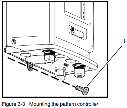
- Loosen the socket head mounting screw from the pattern controller to remove the mounting plate. Retain the mounting screw for re‐installing the mounting plate to the pattern controller.

- One M5 Socket head screw
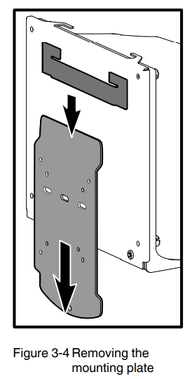
- Slide the mounting plate out from the mounting slot. See Figure 3‐4.

- Mount the mounting plate on a rigid support (e.g., wall or post) to prevent external vibration.
- Slide the pattern controller into the mounting plate.
- Secure the mounting plate by installing the screws provided in the ship‐with kit. Refer to the Parts section for the ship‐with kit part number.
- Position the pattern controller and slide it into the installed mounting plate.
- Using the socket head mounting screw removed in step 2, secure the pattern controller to the mounting plate.
Attach the Quick Reference Guide
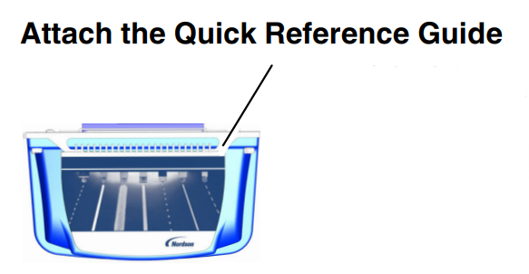
The Quick Reference Guide included in the ship‐with kit provides an overview of the user interface and common pattern generation tasks. Slide the spiral-bound side of the Quick Reference Guide to the two hooks on either side of the top panel of the pattern controller.
Connecting the Spectra 30
![]() WARNING! Equipment must be properly grounded and fused according to its rated current consumption (see ID plate). Failure to follow the safety procedures can result in serious injury.
WARNING! Equipment must be properly grounded and fused according to its rated current consumption (see ID plate). Failure to follow the safety procedures can result in serious injury.
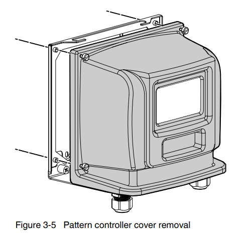
- Remove the pattern controller cover by loosening the four M5 captive screws to access the internal boards.

- Route all the cables through the conduits located on the base panel of the pattern controller, see Figure 3‐6.
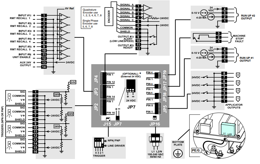
 Refer to the Wiring Diagram for connecting the device-specific cables to the proper location on the corresponding boards.
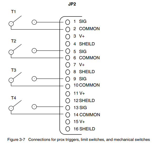
To Disable Open Trigger Warnings
For Prox triggers, Limit switches, and Mechanical Switches.
To prevent trigger warnings from appearing randomly, be sure to make the following connections on the Trigger (JP2) location of the controller board.
Internal Wiring
![]() WARNING
WARNING
Allow only personnel with appropriate training and experience to operate or service the equipment. The use of untrained or inexperienced personnel to operate or service the equipment can result in injury, including death, to themselves and others, and damage to the equipment.
![]() WARNING
WARNING
Equipment must be properly grounded and fused according to its rated current consumption (see ID plate). Failure to follow the safety procedures can result in serious injury.
Important Wiring Details
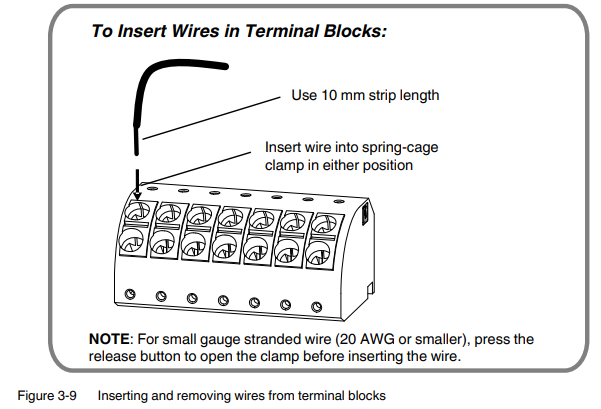
Wire Gauge Range
- JP5 and JP17
5 mm pitch connectors (applicator and run-up),14 – 24 AWG - JP 2, JP3, JP4 and JP7
3.5 mm pitch connectors (triggers, encoders, and system Input/Output), 16 – 24 AWG, solid or stranded - JP16 –
AC Input Plug: 12 – 24 AWG
Insulation voltage rating: 300V
Insulation temperature rating: 70 °C 158°FF) min - JP17 –
5 mm pitch terminal block plug, 14 – 24 AWG - JP18 and JP19 –
3.5 mm pitch terminal block plug, 16 – 24 AWG, solid or stranded
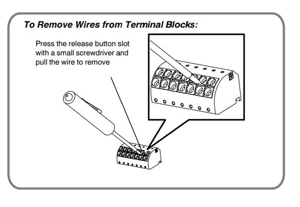
Connect to External 24 VDC Power Supply
Do the following if an external 24 VDC power supply is used:
- Disconnect the existing wires on JP7, and remove them by detaching them from the internal power supply. This prevents the loose wires from shorting to the Control board.
- Connect the positive power lead from the external 24 VDC power supply to JP7 pin 1 and the negative power lead to JP7 pin 3.
- Connect the protective earth to the terminal marked PE inside the pattern controller.
Before Setting Up Spectra 30
![]() WARNING! Allow only qualified personnel to perform the following tasks. Follow the safety instructions in this document and all other related documentation.
WARNING! Allow only qualified personnel to perform the following tasks. Follow the safety instructions in this document and all other related documentation.
Before setting up the pattern controller, make sure of the following:
- The pattern controller cover removed in step 1 under Connect Spectra 30, given earlier, is reinstalled.
- Pattern controller components are connected.
- The pattern controller power cable is connected to a grounded outlet.
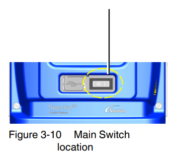
- The pattern controller switch is turned on.
Troubleshooting
![]() WARNING! Allow only personnel with appropriate training and experience to operate or service the equipment. The use of untrained or inexperienced personnel to operate or service the equipment can result in injury, including death, to themselves and others, and damage to the equipment.
WARNING! Allow only personnel with appropriate training and experience to operate or service the equipment. The use of untrained or inexperienced personnel to operate or service the equipment can result in injury, including death, to themselves and others, and damage to the equipment.
![]() WARNING! Observe all safety instructions and regulations concerning energized unit components (active parts). Failure to observe may result in an electric shock.
WARNING! Observe all safety instructions and regulations concerning energized unit components (active parts). Failure to observe may result in an electric shock.
![]() WARNING! Allow only qualified personnel to perform the following tasks. Follow the safety instructions in this document and all other related documentation.
WARNING! Allow only qualified personnel to perform the following tasks. Follow the safety instructions in this document and all other related documentation.
This section contains troubleshooting procedures. These procedures cover common problems that you may encounter. If you cannot solve the problem with the information given here, contact your local Nordson representative for help.
Diagnostics Tools
The Spectra 30 pattern controller has extensive diagnostic tools to assist you in identifying and troubleshooting problems with the system.
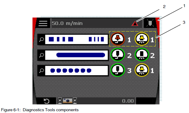
- System Status
- Diagnostic Status Symbol
- Component Diagnostic Symbol
System Status
The background color of the touch screen shows at a glance the status of the system.
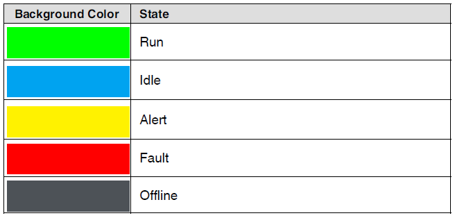
NOTE: If a fault and a warning both exist, the fault takes priority in determining the system status. For more details, refer to the System Status Summary Chart in the System Outputs section given later.
Diagnostic Status Symbols
The diagnostic status symbol in the status bar changes when a problem occurs with the system.
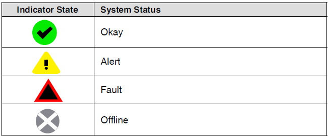
Tap the symbol at any time to open the message log.
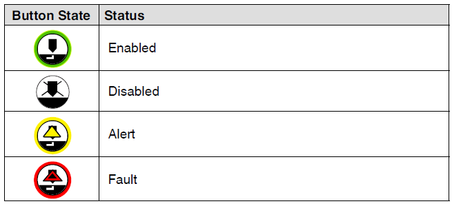
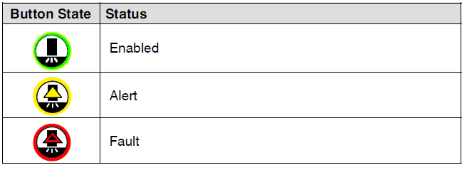
Component Diagnostic Symbols
The components on the home screen will change when a problem occurs with that component.
Applicator Symbols
Trigger Symbols
Pattern Alerts

Message Log
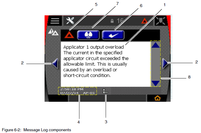
- Message text
- Next/previous message button
- Message scroll indicator
- Time/date stamp
- Message status indicator
- Acknowledge button
- Shortcut button
- Scroll bar
Message Text
Each Fault or Alert Message contains three parts:
- Fault/Alert Name, a short name
- Fault/Alert Description, details of the condition
- Troubleshooting tips, suggested checks to resolve the problem
NOTE: When necessary, use the scroll bar (item 8 in Figure 6‐2:) to see additional text. You can also slide your finger up and down in the message box.
Message Scroll Indicator
The Message Scroll Indicator (item 3 in Figure 6‐2:) shows the number of active and inactive messages and your current position in the log. This indicator contains a maximum of 25 messages.
- Each tall block in the indicator shows an active fault or alert.
- Each short block indicates an inactive fault or alert.
- The triangle indicates your current position in the log.
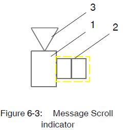
- Tall block
- Short block
- Triangle
Message Status Indicators
The Message Status Indicator (item 5 in Figure 6‐2:) provides the type and status of each message:
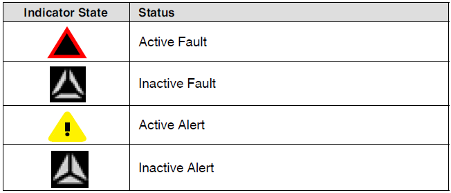
NOTES:
- Active Faults and Alerts are always sent to the beginning of the log, and are sorted by time of occurrence.
- Inactive Faults and Alerts are always sent to the end of the log, and are sorted by time of occurrence.
- To move to the next or previous message, use the left and right message navigation buttons (item 2 in Figure 6‐2:).
- Each message includes a time and date stamp of the message along with a message code (item 4 in Figure 6‐2:).
Resolving Alerts and Faults
When a fault or alert condition occurs, the screen background color flashes red or yellow until the message is acknowledged.

Tap the button (item 6 in Figure 6‐2:) on the Message Log screen to acknowledge the message. After the alert or fault has been acknowledged, the background stops flashing. Depending on the type of fault or alert, holding the acknowledge button may also clear the fault or alert condition, sending it to the inactive section of the log.
If the fault or alert condition continues after the message has been acknowledged, further steps must be taken to resolve the problem. Use the troubleshooting tips in the message log as a guide.
Shortcut Buttons
See item 7 in Figure 6‐2: for the location of the shortcut button. Depending on the type of events that occur, one of the following buttons appears on the Message Log screen:
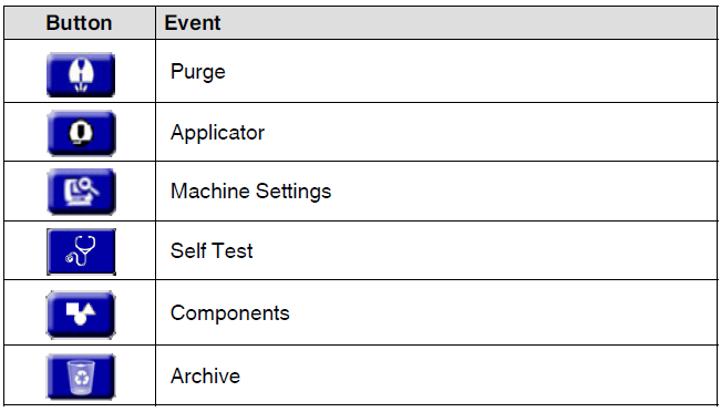
These buttons provide menu shortcuts that are related to the message. The messages provide corrective actions.
System SelfTest
A comprehensive system self‐test is available that loops back outputs to inputs to verify the functions of the controller board hardware. If the system passes the self-test, then the problem is most likely somewhere outside the Spectra 30 pattern controller system.
To access the Self Test screen, do the following:
- Tap the Tools button from the Main Menu.
- Tap the Self Test button.
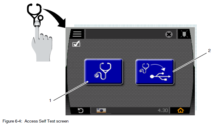
- Run self self-test button.
- Save results to a USB drive button
Self Test Screen Status
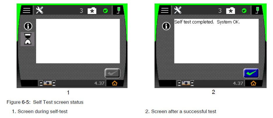
If the self-test fails, a fault or alert will be generated that will provide details about the failure. Tap the Diagnostic icon in the Status Bar to go to the Message Log.

System Outputs
Three system outputs provide system status:
- Ready
An active output indicates that the pattern controller is ready for you to run the line and produce products. The Ready output is not affected by Alerts or Standby. - Alert
An active output indicates that an Alert condition exists. Alert conditions do not normally prevent you from producing products, but should be investigated as soon as possible. - Fault/Machine Stop
The SPDT (Single Pole Double Throw) dry contact output is activated while a Fault condition exists.
Refer to the System Status Summary Chart for details.
NOTES:
Refer to the Internal Wiring Details in Installation, Section 3, for instructions on how to connect the system outputs. Refer to the System Settings in Using the Menus, Section 5, for instructions on how to change the polarity of the system outputs.
System Status Summary Chart
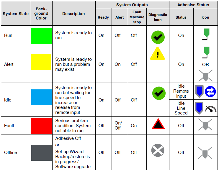
Defining the System Statuses
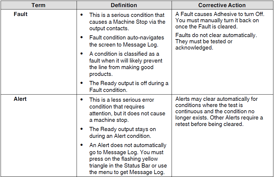

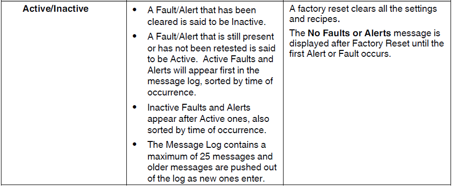
When the System Fails to Start Up
![]() WARNING! Allow only qualified personnel to perform the following tasks. Follow the safety instructions in this document and all other related documentation.
WARNING! Allow only qualified personnel to perform the following tasks. Follow the safety instructions in this document and all other related documentation.
![]() WARNING! The power supply is electrically energized and presents a shock hazard. Use caution while performing the troubleshooting steps below
WARNING! The power supply is electrically energized and presents a shock hazard. Use caution while performing the troubleshooting steps below
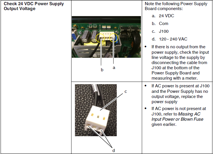
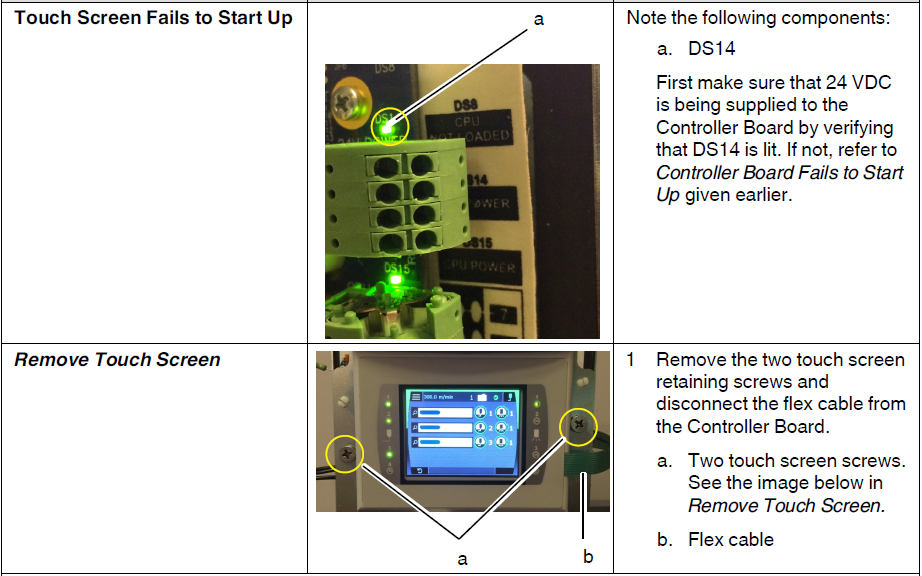
The following tables provide some potential causes for a system failing to power up successfully. Perform corrective actions in this section with the pattern controller cover removed.
Refer to System Schematics in the Specifications section.
Controller Board Issues
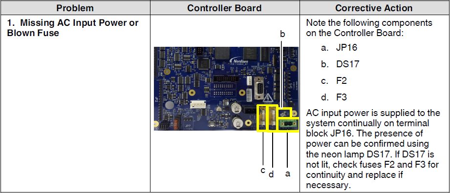
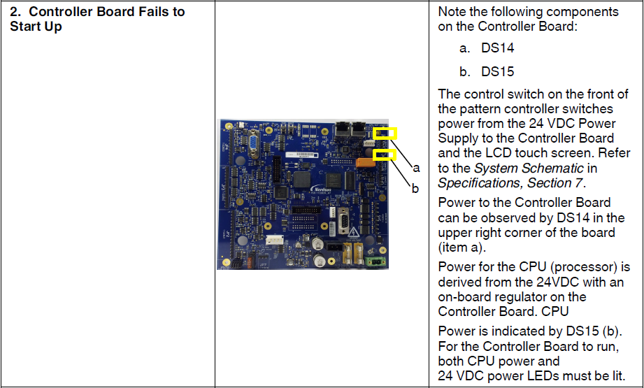
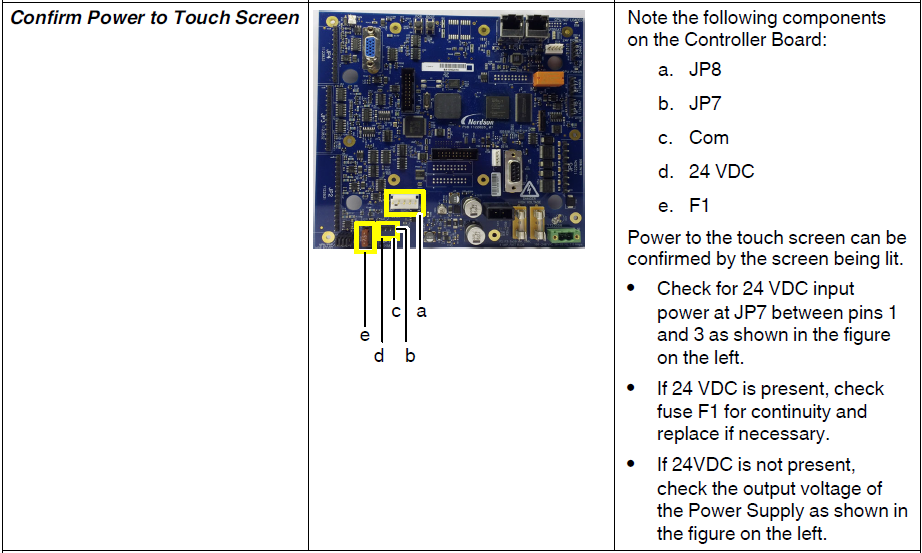
Power Supply Board
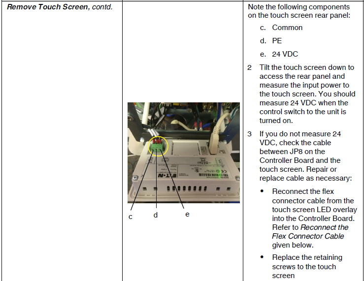
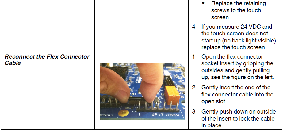
Touch Screen Issues
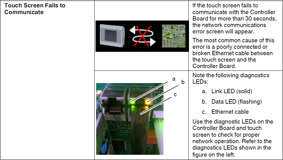
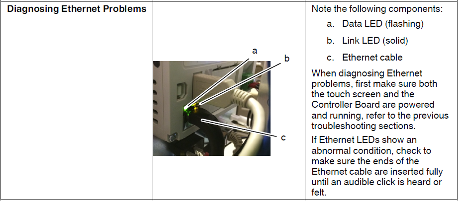
Ethernet Network Communications Issues
Calibration Screen
Tap anywhere on the splash screen to open the Calibration screen. See Figure 6‐7:
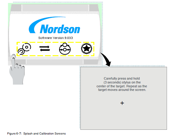
If you do not tap the Splash screen, the Home Screen appears after a brief delay.
Specifications
System Specifications
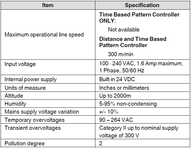
Encoder
Distance and Time-Based Pattern Controller

Interface
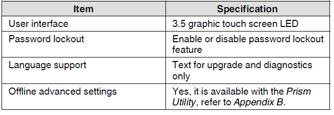
Inputs/Outputs
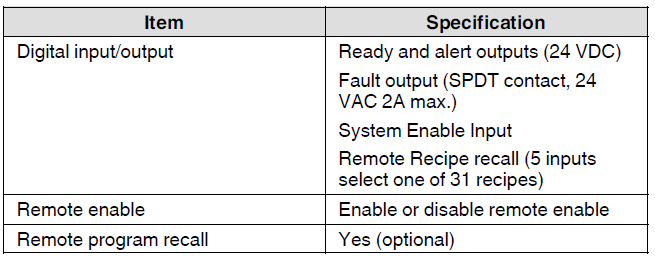
Recipe Memory
- Up to 50 recipes.
Replaceable Fuses
- F1 – 7.5 Amp, 32V mini-blade fuse (P/N 1122386).
- F2, F3 – 5×20 mm fast blow, 4 Amp 250V fuse (P/N 114876)
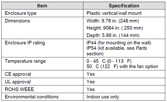
Enclosure
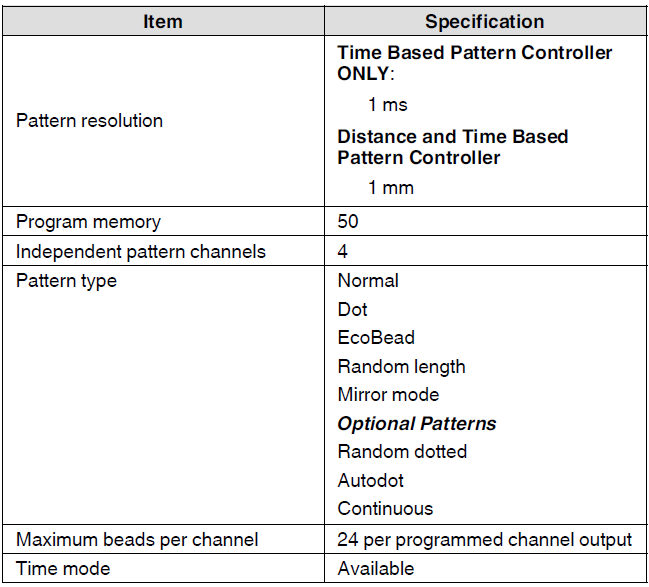
Patterns
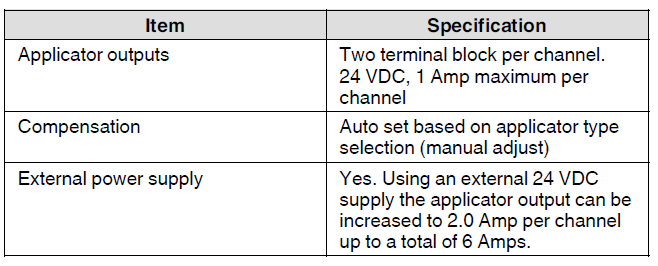
Applicators
Triggers
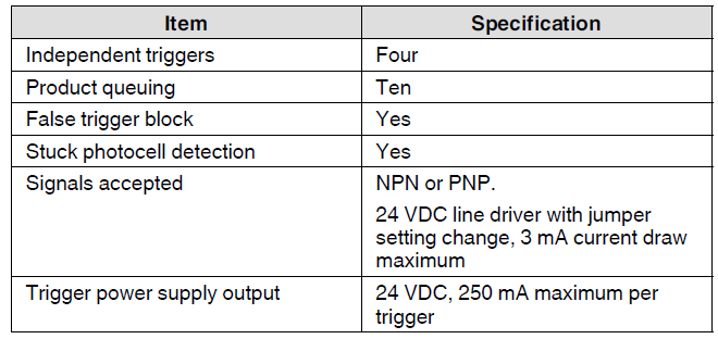
Pressure Run‐up
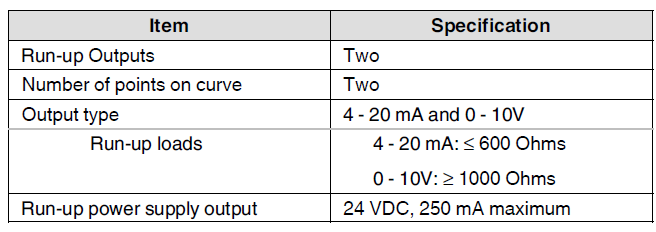
Diagnostics

Add‐on Software License
The three pattern controller configurations (time-based, distance-based, or pressure run-up) can be upgraded by ordering additional licenses(s). These software licenses can be ordered by specific part numbers. Refer to Parts for the software license part numbers.
The add‐on features are:
- Encoder
- Pressure/Run‐up
- Remote recall
- Extra features
To obtain an add-on license, go to the dedicated licensing website https://spectra30-license.nordson.com.
Schematics
System Schematics
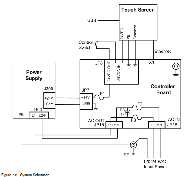
External Power Supply
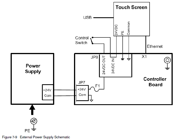
For external power supply installation instructions, refer to Connect to External 24 VDC Power Supply in Installation.
For more manuals by Nordson, visit ManualsLibraryy
Nordson Spectra 30 Pattern Controller- FAQs
What is the Nordson Spectra 30 Pattern Controller used for?
It is used to control adhesive application patterns with precision in packaging and production lines.
How do I power on the Spectra 30 Controller?
Turn the main power switch to ON. The system will initialize and display status on the screen.
How many patterns can the Spectra 30 store?
The controller can store up to 30 different adhesive patterns for quick recall during production.
How do I set up a new adhesive pattern?
Use the control panel to select a channel, enter timing values, and save the pattern for later use.
Does the Spectra 30 support multiple guns?
Yes. It can control multiple adhesive guns at the same time, allowing flexible pattern operations.
How do I check if the system is working correctly?
Verify the display indicators, run a test cycle, and check for proper adhesive bead placement.
What should I do if the controller shows an error code?
Refer to the user manual’s troubleshooting section to identify the code and follow the recommended fix.
Does the Nordson Spectra 30 require regular maintenance?
Yes. Keep the unit clean, check wiring connections, and perform routine inspections to ensure long-term reliability.

 Refer to the Wiring Diagram for connecting the device-specific cables to the proper location on the corresponding boards.