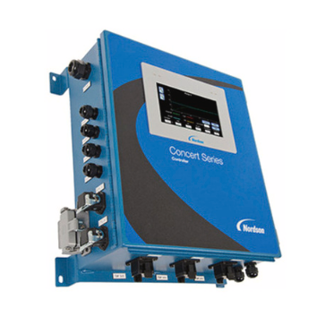
Nordson Universal TruFlow Meter Controller
Description
This manual describes the installation and use of the Nordson Universal TruFlow controller/monitor. When necessary, the reader is referred to the documentation supplied with other Nordson products or products supplied by third parties.
The Universal TruFlow controller/monitor is used in a hot melt adhesive delivery system to control and/or monitor adhesive consumption and add-on weights by providing inline measurement and reporting of adhesive-per-piece data for better process control. The TruFlow controller/monitor includes the following capabilities:
- Adhesive output can be monitored and recorded by individual part, time/day/shift, or current total output.
- Control parameters, warnings, and alarms can be preset to stop the line if dispensing deviates beyond upper or lower dispensing limits.
- The closed-loop encoder feedback can be used to improve the volumetric flow of adhesive during ramp-up and steady-state operation.
Figure 2 shows how the TruFlow controller/monitor is typically used in an adhesive delivery system.
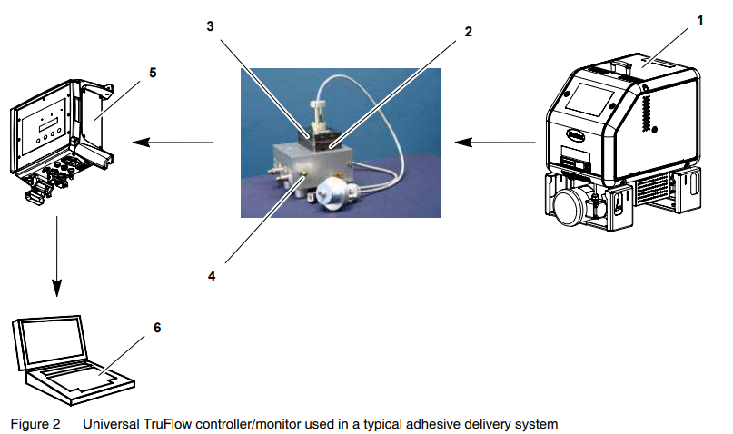
- Melter
- TruFlow metering pump
- Encoder
- Applicator
- TruFlow controller/monitor
- Laptop computer
Intended Use
The Universal TruFlow controller/monitor is specifically designed to:
- Be used with compatible equipment manufactured by Nordson Corporation
- Be used in non-explosive environments
The Universal TruFlow controller/monitor is virtually complete, but is intended to be incorporated into machinery or assemblies by an integrator. The equipment must not be placed into use in a member state of the European Union until the parent machinery or assemblies have been declared by the integrator to conform with the applicable directives of the European Commission.
Limitations of Use
Use the Universal TruFlow controller/monitor only for the purpose for which it is designed. The Universal TruFlow controller/monitor should not be used:
- with any material that creates a health or safety hazard when heated
- in environments that will require the system to be cleaned using a water wash or spray
Unit Identification
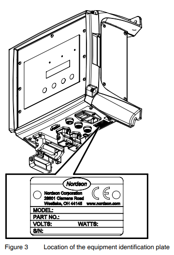
See Figure 3. You will need the model and part number of the controller/monitor when requesting service or ordering spare parts and optional equipment. The model and part number are indicated on the equipment identification plate.
Key Components
Figures 4−5 provide the name and the location of key system components.
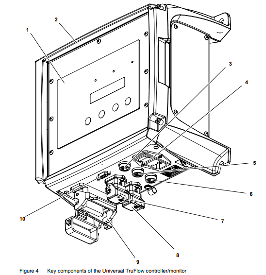
- Operator panel (see Figure 5)
- Enclosure door
- Product sensor input
- Power switch
- Encoder input A
- Encoder input B
- Flow monitor output A (to melter)
- Flow monitor output B (to melter)
- Customer input/output (I/O) connector
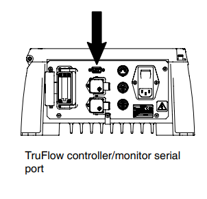
- Serial port (laptop computer connection)
Note: Refer to Table 3 later in this manual for connection details.
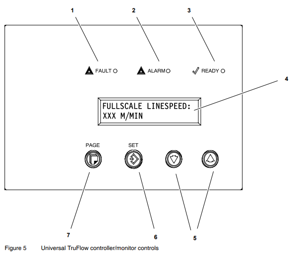
- FAULT LED
- ALARM LED
- READY LED
- Display
- Up/down arrow keys
- SET key
- PAGE key
Installation
Installation involves placing the controller/monitor in the desired location and making the electrical connections.
Electro-Magnetic Compliance Information
This system is classified as Class A, Group 2 under the European standard for limits and methods of measurement, EN 55011.
Experience of Installation Personnel
The instructions provided in this section are intended to be used by personnel who have experience in the following subjects:
- Hot melt application processes
- Industrial power and control wiring
- Industrial mechanical installation practices
- Basic process control and instrumentation
Customer-Supplied Installation Components
In addition to the components provided by Nordson Corporation, installation of the TruFlow controller/monitor requires the following customer-supplied components:
- laptop computer and serial cable
- melter with 0−10V key-to-line input (required only if the monitor/controller will be used for controlling purposes)
- appropriate guarding and signage as required to prevent personal injury during operation and service activities
Install the Controller/Monitor
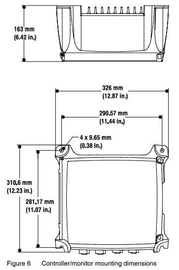
See Figure 6. Carefully unpack and mount the controller/monitor at the desired location:
- Position the controller/monitor as close as possible to the parent machine or production line.
- Ensure that the mounting location provides sufficient clearance around the sides, the base, and the rear of the controller/monitor for easy access to the control panel and connectors.
NOTE: For unhindered air flow, the recommended minimum clearance at the top and base of the controller/monitor is 50 mm (1.96 in.). - Mount the controller/monitor vertically on the wall or post to provide maximum cooling by convection across the heatsink fins.
- Mount the controller/monitor on a rigid support (e.g., wall or post) to prevent external vibration.
Make the Electrical Connections
See Figure 7 and/or refer to Table 3 to make the correct electrical connections for your application.
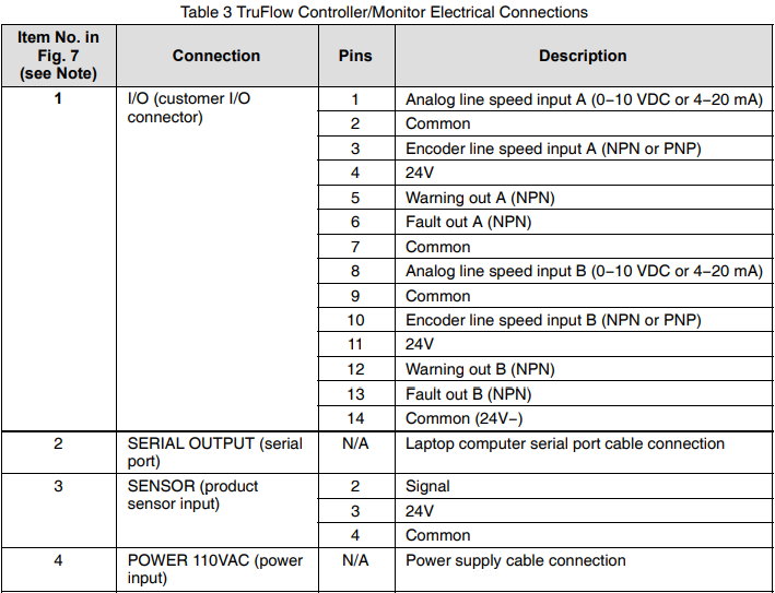
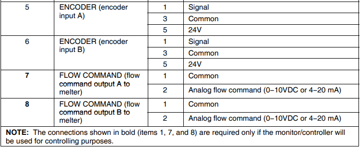
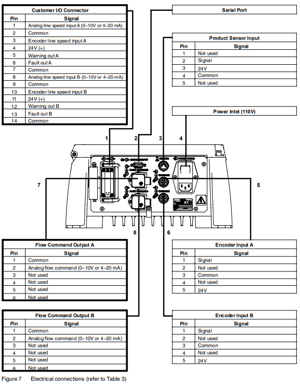
Note: The tables outlined in bold are required only if the controller/monitor will be used for controlling purposes.
Check the Configuration Switch Settings
Perform the following steps to ensure that all configuration switches are properly set. The configuration switches are located on the circuit board assembly, as shown in Figure 8.
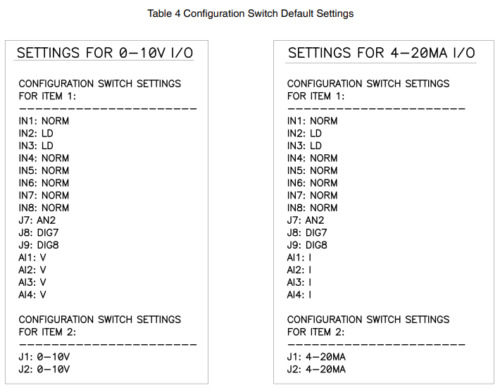
- If you are using a 4-20mA signal, ensure that the configuration switch settings match the default settings shown under Settings for 4−20MA I/O in Table 4.
- If you are using standard NPN or PNP sensors, set IN1 to NORM. If you are using signals that swing from 0−24V (such as solenoid signals), set IN1 to LD.
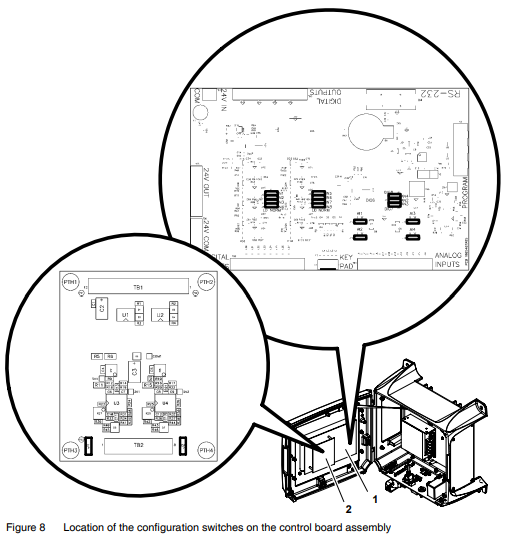
Figure 8 Location of the configuration switches on the control board assembly
- Motherboard
- Daughterboard
View or Change Settings
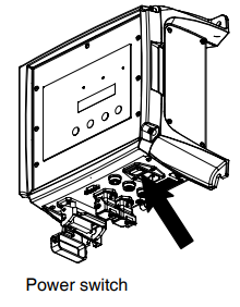
Place the power switch in the on position. The controller/monitor display will go through the startup screens.
The controller/monitor settings may be viewed or changed in two modes: user mode or administrator mode. Use the following procedures to view or change the settings as needed for your application.
To view or reset a parameter in the user mode:
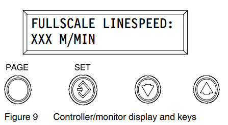
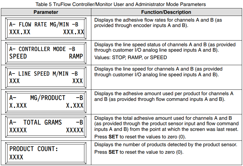
- Press PAGE until the desired parameter is displayed. Refer to Table 5 for the parameters that can be accessed in the user mode.
- As applicable, press SET to reset the parameter value to zero (0).
To view or change a parameter in the administrator mode:
- Simultaneously press and hold the Up/Down arrows for at least 5 seconds. The display will briefly flash “Administrator Mode Enabled.”
- Press PAGE until the desired parameter is displayed. Refer to Tables 5 and 6 for the parameters that can be accessed in the administrator mode.
- If there is only one value for the selected parameter, press the Up/Down arrows to scroll to the desired setting.
If there are multiple values for the parameter, press SET until the desired value is displayed, then press the Up/Down arrows to scroll to the desired setting.
NOTE: The word “Set” will appear in front of the value that can be set. - Simultaneously press and hold the Up/Down arrows for at least 5 seconds to exit the administrator mode. The display will briefly flash “Administrator Mode Disabled.”
NOTE: Refer to To view or reset a parameter in the user mode or To view or change a parameter in the administrator mode earlier in this section for the procedures for viewing or changing a parameter.
NOTE: No parameters can be changed in the user mode.
NOTE: Refer to To view or change a parameter in the section earlier in this document for the procedure for viewing or changing a parameter.
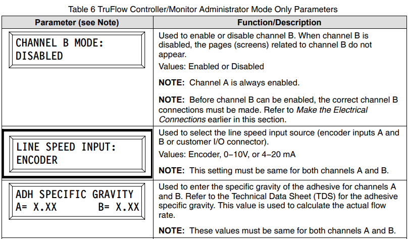
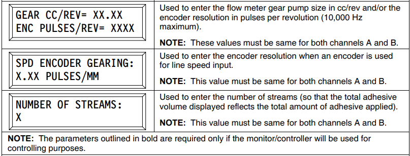
NOTE: Refer to To view or change a parameter in the section earlier in this section for the procedure for viewing or changing a parameter.
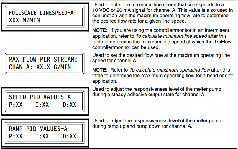
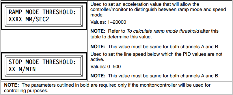
NOTE: Refer to To view or change a parameter in thesectione earlier in this document for the procedure for viewing or changing a parameter.
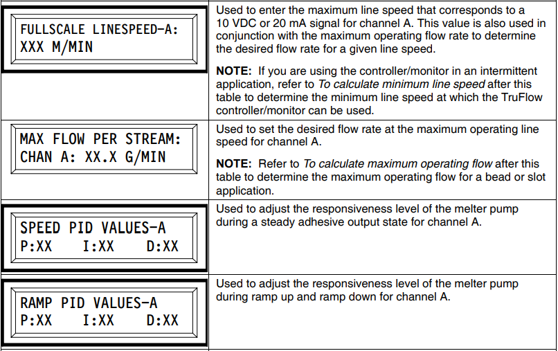
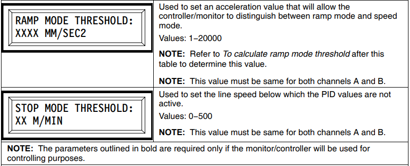
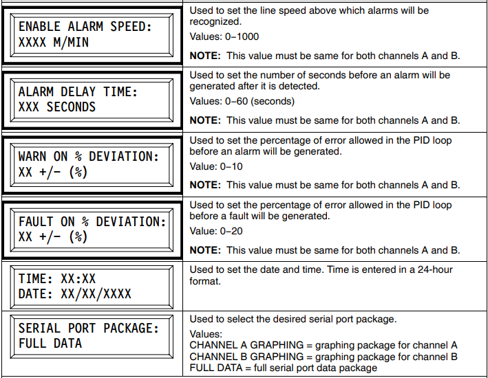
NOTE: The parameters outlined in bold are required only if the monitor/controller will be used for controlling purposes.
NOTE: Refer to To view or change a parameter in the section earlier in this document for the procedure for viewing or changing a parameter
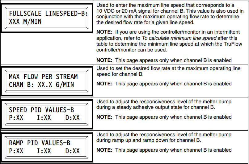
NOTE: The parameters outlined in bold are required only if the monitor/controller will be used for controlling purposes.
To calculate the minimum line speed
If the TruFlow controller/monitor is used in an intermittent application, there is a minimum speed at which the controller/monitor can be used to provide feedback to the melter. Use the following formula to calculate the minimum speed:
MLS = 0.6 × GL
Where:
MLS = minimum line speed (m/min)
GL = gap length (mm)
To calculate the maximum operating flow
Use the following formulas to calculate the maximum operating flow for a bead or slot application. For other applications, contact your Nordson representative for assistance.
Bead:

Where:
MOF = maximum operating flow (gm/min)
D = diameter of bead (mm)
L = length of bead (mm)
ρ = density of adhesive (gm/cm3)
PPM = products per minute
Slot:
MOF = LS × GSM × w
Where:
MOF = maximum operating flow (gm/min)
LS = line speed (m/mm)
GSM = grams per square meter (gsm2)
w = width of pattern (m)
To calculate the ramp speed threshold
Use the following formula to calculate the ramp speed threshold value:

WhereA
a = acceleration (mm/sec2)
LS = line speed (m/min)
tR = ramp time in seconds (s)
Monitor Adhesive Flow
The TruFlow controller/monitor can be used to view active and/or desired material flow rates in real time. The desired flow rate is displayed only if the line speed input, maximum flow rate, and full-scale line speed are entered.
Monitor Flow Rate Using a Computer
- Connect the computer serial cable to the TruFlow controller/monitor.
- Change the TruFlow controller/monitor setting for SERIAL PORT PACKAGE to one of the following:
- CHANNEL A GRAPHING
- CHANNEL B GRAPHING
NOTE: Refer to View or Change Settings under Installation to change the TruFlow controller/monitor settings.
- On the computer, open a serial graphing utility software application. Select the appropriate COM port and select 38400 as the Baud rate.
NOTE: If you are using the monitor/controller to monitor actual flow only (e.g., there is no desired flow) and the line representing actual flow is a straight line at the top of the graph, raise the value on the corresponding MAX FLOW PER STREAM page on the monitor/controller until the graph can be properly seen. Refer to View or Change Settings under Installation as needed to change the TruFlow controller/monitor settings.
NOTE: You can obtain a free serial graphing utility on the Internet. Serial Grapher by P & E Microcomputer Systems is an example of a serial graphing utility.
Collect Data Using a Computer
The raw data from the TruFlow controller/monitor can be saved to a computer to be processed and analyzed using the TruFlow AutoFormat Macro.
NOTE: Microsoft Excel is required to run the TruFlow AutoFormat Macro.

- If you have not already done so, obtain the TruFlow AutoFormat Macro.xls file. Contact your Nordson representative for assistance as needed.
- Connect the computer serial cable to the TruFlow controller/monitor.
- Before collecting data, press SET for the following parameters to reset the counter:
- A- TOTAL GRAMS -B
- PRODUCT COUNT
NOTE: Do not press SET while data is being collected—doing so will cause the data output to reset.
- Change the TruFlow controller/monitor setting for SERIAL PORT PACKAGE to FULL DATA.
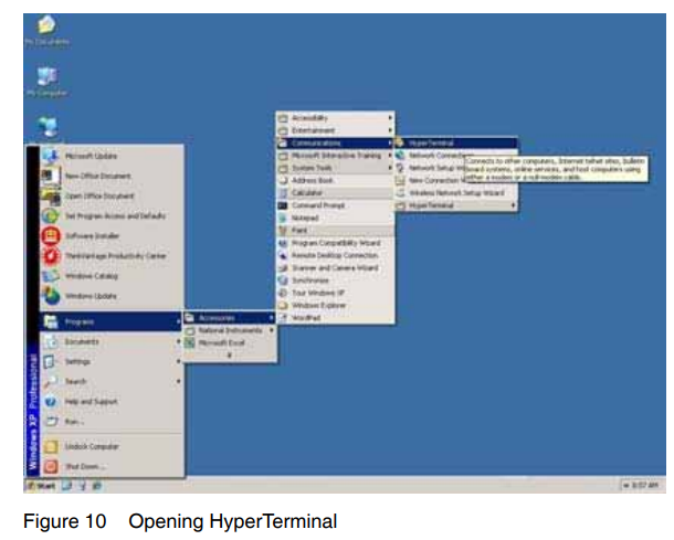
NOTE: Refer to View or Change Settings under Installation to change the TruFlow controller/monitor settings. - See Figure 10. On the computer, open the HyperTerminal software application.
When opened, the HyperTerminal software will prompt you to create a new connection.
NOTE: HyperTerminal is bundled with all Microsoft Windows operating systems from Windows 95 up to and including Windows XP. It is not included with Windows Vista or Windows 7 operating systems.
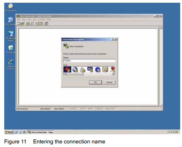
- See Figure 11. Enter TruFlow for the name of the new connection, choose an icon, and click OK.
A new dialog box will be displayed.
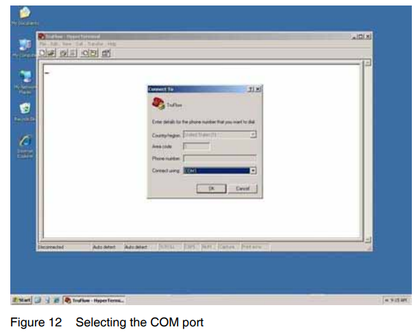
- See Figure 12. Under the Connect Using drop-down menu, select the appropriate COM port.

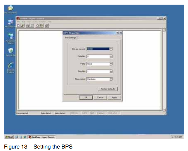
- See Figure 13. Set the Bits Per Second to 38400 and click on OK.

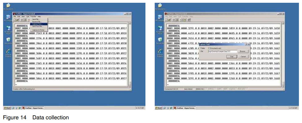
- Follow these steps to begin data collection in HyperTerminal:
- Select the Transfer tab.
- Click on Capture Text.
- Name the text file, then click on Start.
Data collection will begin. Data can be collected for a maximum time of 1 hour and 40 minutes. All data must be collected within this time frame.
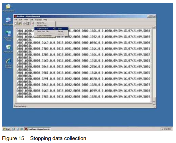
- See Figure 15. To stop data collection and complete the text file, select the Transfer tab and then click on Capture Text > Stop.

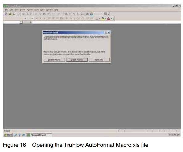
- See Figure 16. To process the text file, open the Excel file titled TruFlow AutoFormat Macro.xls and enable all macros by clicking on the appropriate button when prompted.

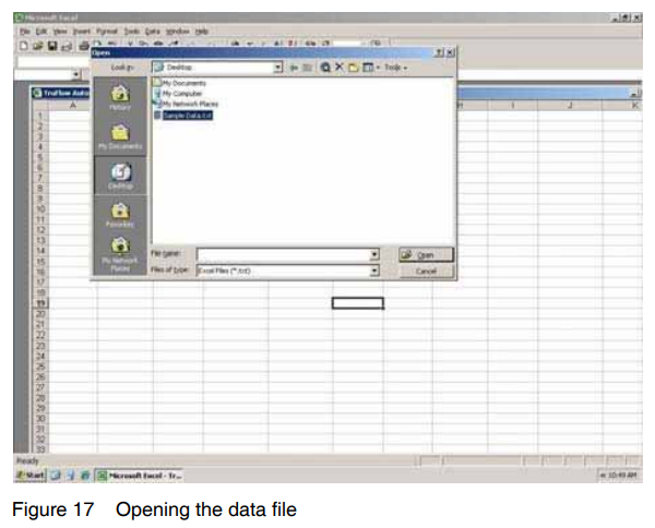
- See Figure 17. Navigate to the directory that contains the saved text file and open the file.
The macro will process the data and then open a window.
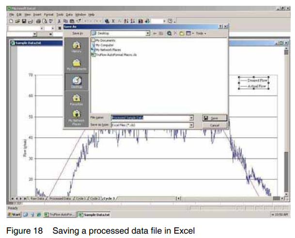
- When the window showing the processed data opens, save the newly created Excel file.

- To process another file, press Ctrl + T to restart the macro to open another file.
Manually Tune PID Settings (For Controlling Only)
CAUTION! This procedure is provided as a guideline only. The PID settings for each application will differ. Exact values cannot be provided.

Follow this procedure to use the TruFlow controller/monitor to regulate flow from the melter. This is accomplished by fine-tuning the ramp and speed PID (proportional, integral, derivative) settings that control the level of responsiveness of the actual flow rate to the desired flow rate during ramp mode and speed mode.
NOTE: An intermittent pattern will have different PID values than a continuous pattern with the same monitor/controller inputs.
- Connect the computer serial cable to the TruFlow controller/monitor.
- Change the TruFlow controller/monitor setting for SERIAL PORT PACKAGE to one of the following, as applicable:
- CHANNEL A GRAPHING
- CHANNEL B GRAPHING
- Open the serial graphing utility on your computer and enter the correct parameters to detect the data (refer to Collect Data Using a Computer earlier in this section) so that the visual feedback is immediate, which will assist in manual tuning.
- On the TruFlow monitor/controller, set the I and D values to zero (0).
NOTE: These steps are for one set of PIDs at a time (for example, the SPEED PID VALUES parameter for channel A contains one set of PIDs, and the SPEED PID VALUES parameter for Channel B contains another set of PIDs). Refer to View or Change Settings under Installation as needed to change the TruFlow controller/monitor settings. - Increase the P values until the actual flow oscillates around the setpoint (as viewed on the serial graphing utility). Then set P to approximately half of that value.
NOTE: This is referred to as a quarter amplitude decay-type response. - Increase I until any offset is correct for the process. Too much will cause instability.
- As required, increase D until the actual flow responds quickly enough to reach its reference after a load disturbance.
NOTE: Too much D will cause excessive response and overshoot. A fast PID response usually overshoots slightly to reach the setpoint more quickly, but some systems cannot accept overshoot, in which case the system will require a P setting that is significantly less than half that of the P setting that is causing oscillation. Table 7 shows the effects of fine-tuning PID settings.

Maintenance
Table 8 provides recommended maintenance activities and a schedule for performing those activities. Base how often you perform maintenance on your operating conditions.

Troubleshooting
Troubleshooting begins when the flow of adhesive from the applicator stops or diminishes unexpectedly or when a control system alerts you of a problem through an alarm or visual display. This section covers only the most common problems you may encounter. If you cannot solve a problem with the information given here, contact your local Nordson representative for help.
For additional troubleshooting information, refer to the manuals provided with the other equipment used in the hot melt system.
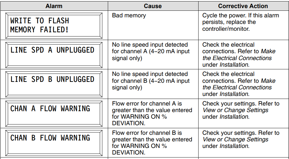
TruFlow Controller/Monitor Alarm Troubleshooting

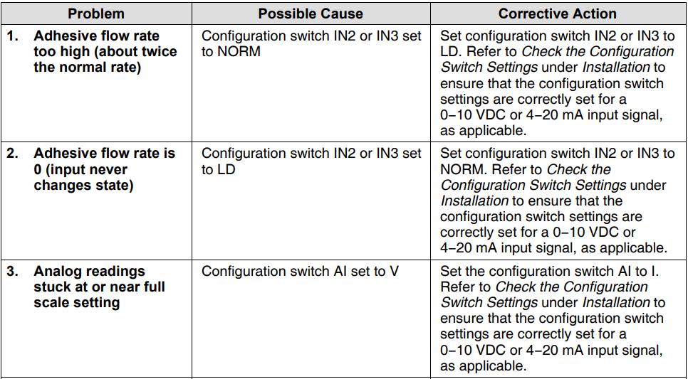
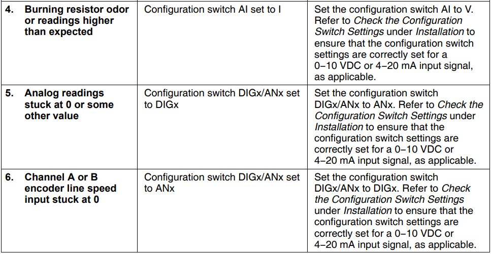
Adhesive Flow Troubleshooting
Control Panel Board Assembly Replacement
![]() WARNING! Risk of electrocution! Disconnect and lock out electrical power to the equipment. Failure to properly disconnect power can result in personal injury, including death.
WARNING! Risk of electrocution! Disconnect and lock out electrical power to the equipment. Failure to properly disconnect power can result in personal injury, including death.
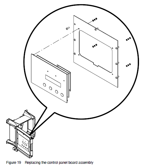
- Place the controller/monitor power switch in the off position and disconnect and lock out power to the controller/monitor. See Figure 19.
- Remove the four screws that secure the control panel board assembly, and then remove the assembly.
- Disconnect all power and control cables from the board assembly.
CAUTION! Before removing the new board assembly from its anti-static bag, ground yourself by touching any bare metal part of the equipment chassis or any grounded structure. Failure to properly ground yourself can cause electrostatic discharge, resulting in damage to the board assembly. - Connect the power and control cables to the new board assembly and secure the assembly to the controller/monitor with the screws removed previously.
- Restore power to the controller/monitor and switch the controller/monitor on. Verify that the controller/monitor starts normally. Refer to View or Change Settings under Installation to change settings as needed.
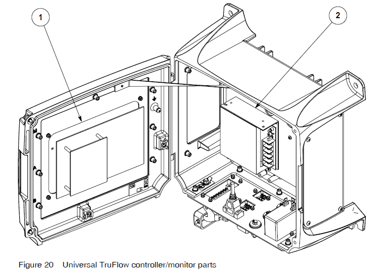
Parts
See Figure 20.

Technical Data
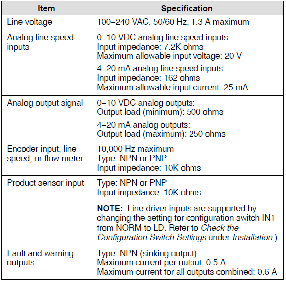
Specifications
Operating Conditions

Electrical
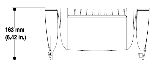
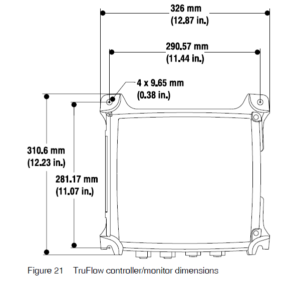
Dimensions
For more manuals by Nordson, visit ManualsLibraryy
Nordson Universal TruFlow Meter Controller- FAQs
Q1. What is the Nordson Universal TruFlow Meter Controller used for?
It is designed to accurately monitor and control adhesive or fluid flow in dispensing systems, ensuring consistent application and reduced waste.
Q2. How do I start up the TruFlow Controller?
Power on the unit, confirm the system connections, and select the proper meter and mode from the control panel before beginning operation.
Q3. How can I calibrate the TruFlow Meter?
Follow the calibration procedure in the menu, enter the required parameters, and confirm readings match the expected flow rate. Calibration ensures precision and reliability.
Q4. What does the display show during operation?
The screen displays real-time flow rate, total dispensed volume, system status, and alerts if conditions go out of set limits.
Q5. How do I change operating parameters?
Use the keypad or touchscreen to access the settings menu. You can adjust flow limits, alarm thresholds, and operational modes according to your process needs.
Q6. Why is my controller showing a flow error alarm?
A flow error usually indicates a blocked line, incorrect calibration, or insufficient material supply. Check hoses, pump pressure, and recalibrate if needed.
Q7. How do I reset the controller after an error?
Press the reset button or use the on-screen reset command. If the alarm persists, troubleshoot the cause before resuming operation.
Q8. What maintenance is required for the TruFlow Controller?
Regularly check electrical connections, clean the exterior, verify sensor accuracy, and inspect flow lines for blockages to keep the system working efficiently.

