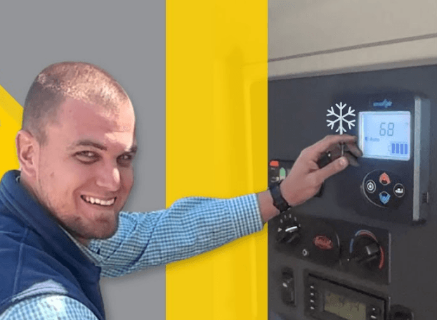
Paccar SmartAir eHVAC System Controller
GENERAL SAFEY INSTRUCTIONS
A number of alerting messages are in this manual. Please read and follow them. They are there for your protection and information. These messages can help you avoid injury to yourself or others and help prevent costly damage to the vehicle.
Warnings, Cautions, and Notes
Key symbols and “signal words” are used to indicate what kind of message is going to follow. Pay special attention to instructions prefaced by symbols and signal words “WARNING”, “CAUTION”, or “NOTE”. Please do not ignore any of these alerts.
EXTERNAL COMPONENT IDENTIFICATION AND LOCATION
Fuses
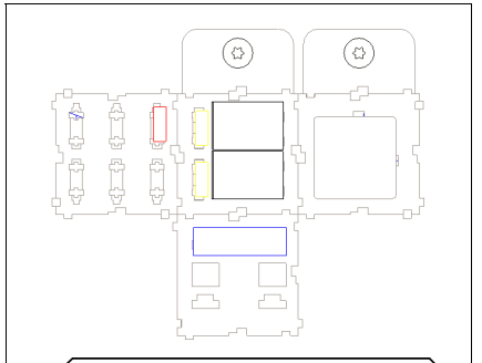
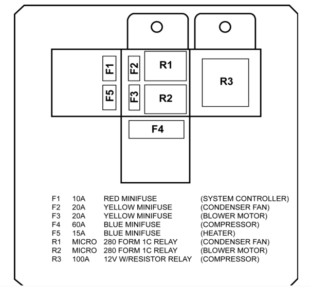
Fuses and Relays
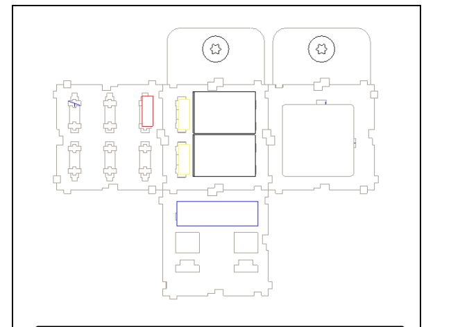
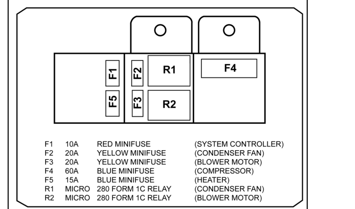
Fuses and Relays (Units built 8/1/2016 to Present)
F1 Fuse 10 Amp (Mini)
This fuse provides short circuit protection for the System control
NOTE : Removing fuse F1 for 10-15 seconds will reset the system controller to factory default settings.
Location: on the control center.
F2 Fuse 10 Amp (Mini)
This fuse provides short circuit protection for the condenser fan
HVAC: SmartAir eHVAC System
Location: on the control center.
F3 Fuse 20 Amp (Mini)
- This fuse provides short circuit protection for the evaporator blower.
- Location: on the control center.
F4 Fuse 60 Amp (Maxi)
- This fuse provides short circuit protection for the compressor.
- Location: on the control center.
Relays
- Location: on the control center.
- R1. This relay controls the voltage to the condenser fan.
- R2. This relay controls the voltage to the linear power module and evaporator blower.
- R3. This relay controls the voltage to the compressor controller.
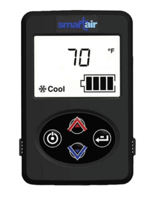
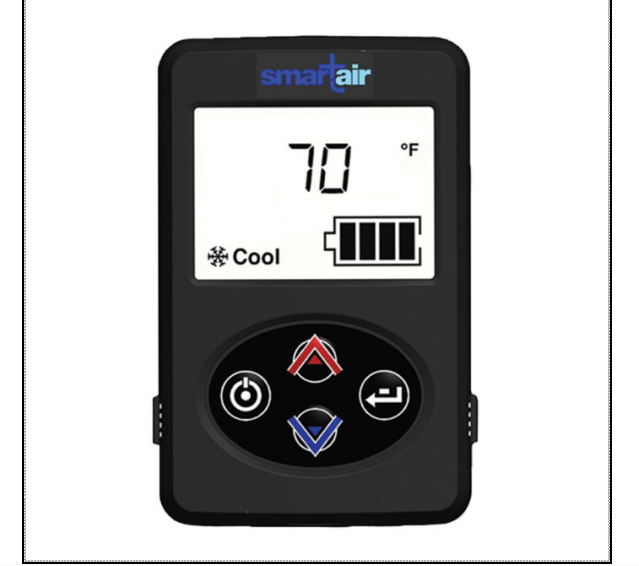
Fan and Temperature Control Display LED Display
Allows for temperature and Blower speed adjustment of the EHVAC (Electrical Heating and Ventilation Air Conditioning) unit when operating in Auto, cool or heat mode. A/C Unit – stops when unit is shut off or batteries are
depleted
Fan and Temperature Control Display
Auxiliary heater will shut down when batteries are depleted but will continue to run through the cool down cycle. Also displays hours of service, battery health and service items.
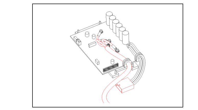
System and Compressor Controller
This device controls the unit and the output voltage to the variable speed compressor. It is located under the large access cover.
System and Compressor Controller
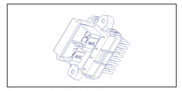
Linear Power Module
This module controls the amount of voltage delivered to the evaporator blower creating variable blower speeds. It is located in the return air in front of the evaporator coil.
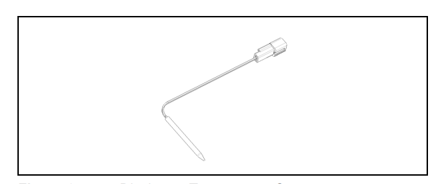
Discharge Temperature Sensor – Freeze Switch
This sensor monitors the evaporator outlet temperature as it enters the vehicle duct system.
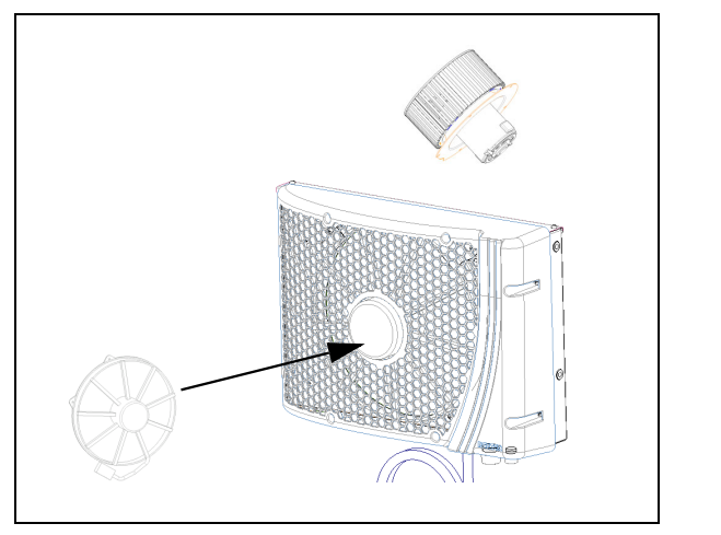
Evaporator Blower
This blower pulls air through the evaporator coil and blows conditioned air into the interior of the sleeper.
Condenser Fan
This blower draws air through the condenser coil to cool the refrigerant flowing through the system.
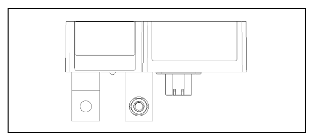
Battery Management System (BMS)
This device monitors the auxiliary batteries for state of charge, communicates with the EHVAC system and controls the battery separator solenoid. LED light on this device indicates power to the device and does not provide diagnostics. Power inputs to this device are fuse protected. If one of the BMS fuses blows, the solenoid will disengage.
Battery Separator
This device connects the truck batteries to the EHVAC batteries. When the starting batteries are at or above 13.2 volts, the battery management device will engage the solenoid to allow the alternator to charge the auxiliary batteries. When the voltage drops to or below 12.5 volts the battery management system will disengage the solenoid to prevent the truck starting batteries from being discharged below the engine start level.
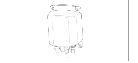
Battery Separator Solenoid, located in the battery box.
INTERNAL COMPONENTS
High Pressure Switch
This normally closed brazed pressure switch will open and prevent the operation of the compressor due to high internal pressure. It is NOT serviceable.

High Pressure Switch
Compressor
This unit is part of the hermetically sealed refrigeration system.
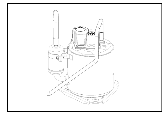
Compressor
Thermal Limit Switch on Compressor
This is a normally closed (auto reset) switch to protect the compressor from high temperature.
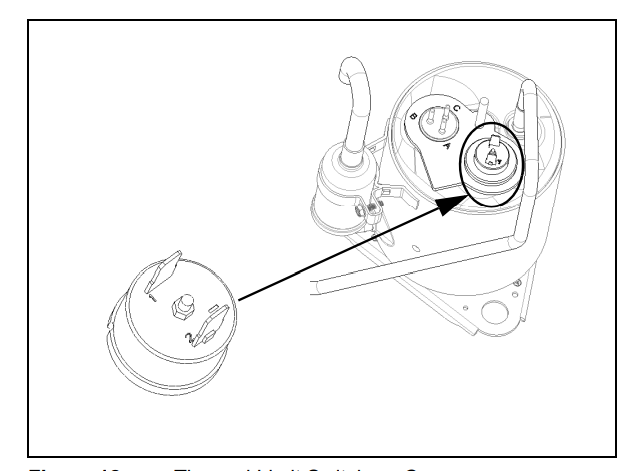
Thermal Limit Switch on Compressor
Evaporator Inlet Filter
This filter protects the evaporator coil from dust and debris. It is washable and should be serviced periodically during routine maintenance.

Evaporator Inlet Filter
When necessary, the Check Filter indicator will notify you that the EHVAC filter must be cleaned or changed. To reset “Check Filter” – at screen 1 press and hold enter button for 3 seconds.
A/C System Diagnostic
Check service screens before troubleshooting
NOTE: Removing fuse F1 for 10-15 seconds will reset the system controller to factory default settings.
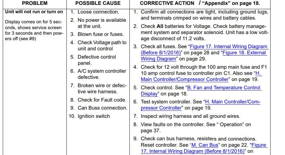
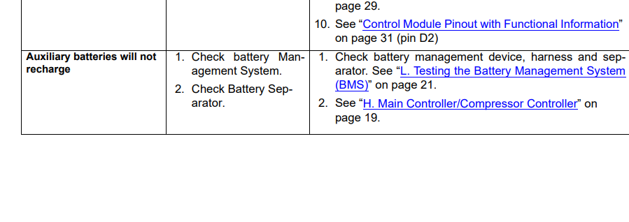
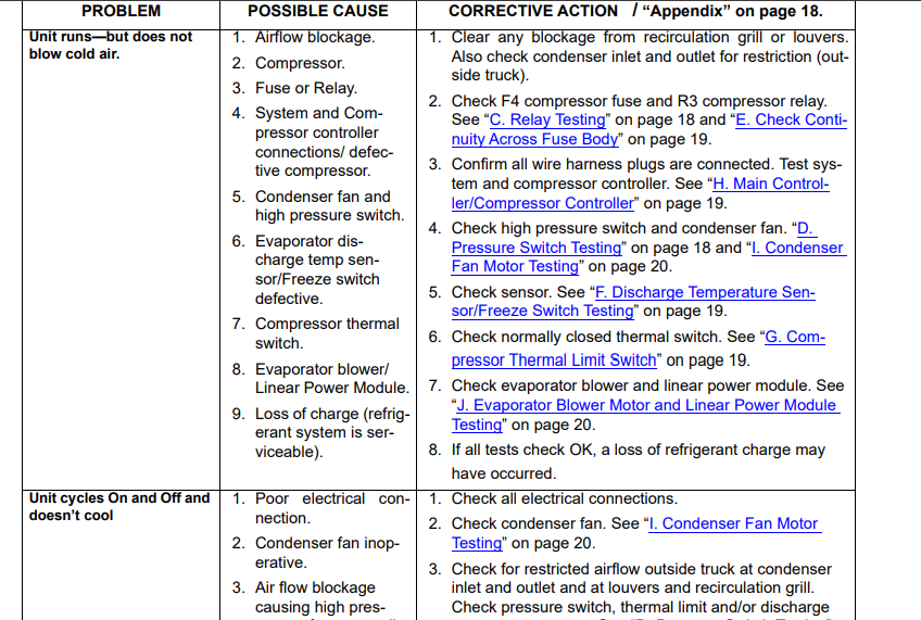
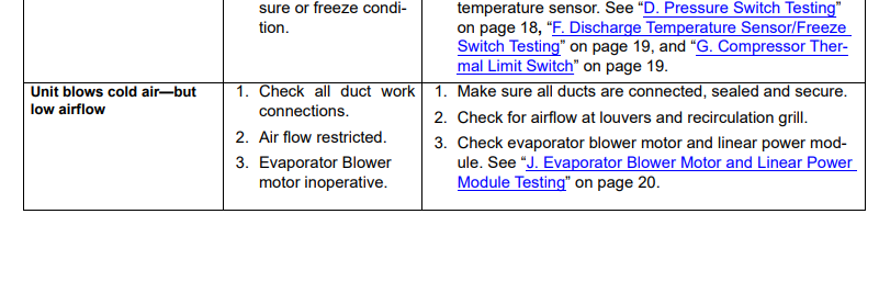
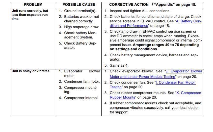
ESPAR Heating System Diagnostic Table
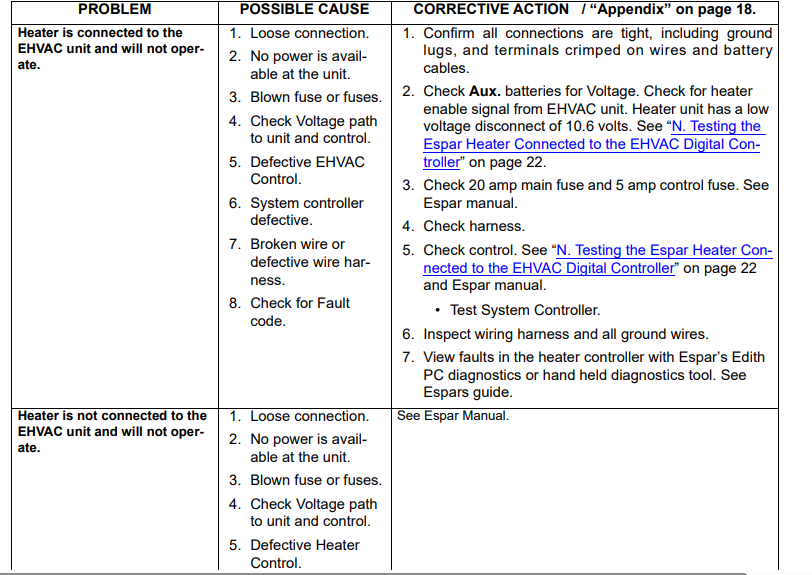


Appendix
Battery Condition and Performance
Battery Voltage is critical for system operation. Special attention should be given to both sets of batteries.
NOTE: Poor quality batteries or a weak alternator will have a negative impact on unit run time. Always maintain the best possible batteries and charging system.
Load test and maintain batteries as required by the manufacturer. Battery symbol in diagnostics screen indicates battery health. This is created after many cycles. If batteries have been disconnected recently this symbol will reset. Several cycles will be needed to get accurate battery health.
Fan and Temperature Control Display
With the control off: check for 12 VOLT at and from F1 10 amp fuse to the connector on rear of control, terminal 1. Terminal 7 is negative. Check for 12 volts at control terminal 6 (wake up) coming from the main/ compressor controller terminal D6. Pushing the control (on) will switch this input from the main controller to ground at the control
panel. This signals the main control to start the system. When control is on the wake up signal should be less than 1 volt.
Relay Testing
With relay unplugged, confirm there is 12 VOLT on the sockets where 85 and 30 relay terminals are connected. If you do not have 12 VOLT here check fuses, wiring and battery connections
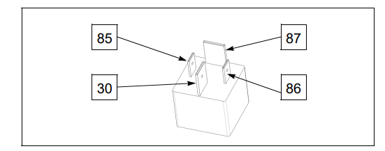
Now, with relay unplugged, check across terminals 85 and 86 of the relay, using an OHM meter. You should have approximately 90 ohms + or – 10% at 68°F (20°C). This is measuring the resistance through the relay coil. If you do not, replace relay.
Overview
When you turn the EHVAC unit on, if all safety switches are okay, such as the high pressure switch, temperature sensor / freeze switch and the compressor thermal limit switch, the Main / Compressor controller will connect the compressor relay, condenser fan relay and the evaporator blower relay terminals 86 to ground at their respective terminals D10, D11 and D12 at the controller. This will close the contacts 30 and 87 of all 3 relays and allow power to each component.
You should now have 12 VOLT passing through the relays on spade terminals 87. This provides power to fuses F2, F3 and F4, continuing to the Linear Power Module, evaporator blower, condenser fan and the compressor controlling section of the Compressor Controller Assembly.
With relay plugged in: turn the unit on. If you do not have 12 VOLT on terminal 87, check across terminals 85 (+) an 86 (-). You should have 12 VOLT. If you do not, you may have a defective harness or system controller. If you have 12 VOLT here and do not have 12 VOLT on terminal 87 your relay is defective. The internal coil of the relay is energized but the contacts are not closing. Replace the relay
If you have 12 VOLT on terminal 87 and the compressor,ncondenser fan or evaporator blower does not run you could have a defective component such as evaporator blower, condenser fan or compressor controller. See testing “J. Evaporator Blower Motor and Linear Power Module Testing” on page 20, “I. Condenser Fan Motor Testing” on page 20, and “H. Main Controller/Compressor Controller” on page 19.
Pressure Switch Testing
You must remove top covers to access the switch. The brazed “A. High Pressure Switch” on page 12 is not removable. This switch is normally closed. When the unit is off for a few minutes, unplug the System Controller and check between pins D2 and D5, you should always have continuity. If you do not, you may have a broken wire, bad connection, high pressure situation or defective switch. If the pressure, harness and connections are okay, the EHVAC unit will have to be replaced.
Check Continuity Across Fuse Body
Fuse does not look blown. Remove fuse from fuse holder. Using a meter, check for continuity across the fuse. You can check for voltage at and through the fuse using a DC volt meter, with the fuse installed.
Discharge Temperature Sensor/Freeze Switch Testing
Location: Between evaporator coil and intake side of blower. The freeze switch is a temperature sensor. To verify the
condition you will need a Volt/OHM meter.
If a freeze condition occurs, the unit will stop the compressor. If the freeze condition leaves, the compressor will restart and the unit will continue to run. Check resistance (ohms) value at the system controller with the 32 pin connector disconnected. You should read a resistance across terminals D3 (pos) and D5 (neg) within the range listed on the “Table 4. Discharge Sensor
Freeze Switch Testing Chart” on page 27. If you cannot read the resistance, check at the sensor connection. If you read the resistance here, and it’s within the range allowed, you have a defective harness. If you cannot read the resistance or it is not within the given range, your sensor is defective.
Compressor Thermal Limit Switch
You must remove the top cover and the plastic shield on top of the compressor, to access the switch. This device is a normally closed switch. If the compressor gets too hot, the thermal limit switch will open and the compressor will stop. Checking with a meter you should always have continuity between the two terminals when it is cool.
Main Controller/Compressor Controller
See updated information on “Service Instructions for Ring Terminal / Controller and Compressor” on page 33 You must remove the cover. Do not attempt to test the controller or compressor until you have completely eliminated all other possibilities.
Overview
When you turn the Peterbilt EHVAC unit on, if all safeties are okay, such as the high pressure switch, temperature sensor / freeze switch and the compressor thermal limit switch, the Main / Compressor controller will connect the compressor relay, condenser fan relay and the evaporator blower relay terminals 86 to ground at their respective terminals D10, D11 and D12 at the controller. This will close the contacts 30 and 87 of all 3 relays and allow power to each component. The compressor and evaporator blower will begin to operate at a speed determined by the manual control panel. The condenser fan will run at normal operational speed.
Initial start up, the system defaults to Auto Mode, Blower speed 1 and 60°F set point. After the settings are changed for the first time, they will always default to the last setting.
Use the following steps to check the controller:
- With the control switch off – check for 12 VOLT from F1 10 amp fuse to the back of the control.
- Now check for 12 volts at switch terminal 6 (wake up) coming from the main/ compressor controller terminal D6. Turning the unit on will switch this 12 volt input from the main controller to ground at the control panel. This signals the main control to start the system.
- With a correct 12 volt signals to and from the control, now check for (ground) signals to relays on D10, 11 and 12. All relays should be closed and all terminals # 87 should have 12 volts. If you lose any signals from the controller it must be replaced.
- With relays closed, the main controller will now signal each component to start. The evaporator blower receives its power from the linear power module. Safety controls must be in a normal state for the above signal to operate the unit.
- If all signals are correct and the safety controls thermal limit on compressor, high pressure switch and temp sensor /freeze switch are okay, the control is calling for cold and the sleeper temperature is above 60 degrees, you should have voltage out on the three wires connected to the compressor terminals: A – Blue, B – Orange and C – Yellow. (ABC – BOY), and the compressor should run.
- If the compressor does not operate, disconnect the three wires from the compressor. You will have to remove plastic cap from the top of compressor.
- Using a volt meter check each wire, positive on (blue, orange or yellow) negative to battery ground. If you do not have a 6 volt pulse voltage out on each wire, replace the controller. Pulse voltage means the controller will cycle to each colored wire. You should see the voltage appear and disappear continuously.
- If you do have a 6 volt pulse voltage out and the compressor does not run you have a defective compressor. Contact the Peterbilt Service line
Condenser Fan Motor Testing
First do a visual inspection of all fan parts.
NOTE This fan cycles on and off with the compressor! Before testing fan, start the unit, make sure the control is set for full cold and the temperature in the truck will allow the control to attempt to start the compressor and fan.
Turn the unit on, you should have 12 volts across terminals 1 and 2 at the condenser fan connector. If you do not have 12 volt at the fan, check fuse F2 And relay R1. If condenser fan 12 volt power is okay, check condenser speed signal from C7 on main controller. This voltage will vary depending on requested speed: approximately 1.6 for low, 2.6 for high. If all voltages are correct, and the fan does not run, it is defective, and needs to be replaced.
Using a DC ammeter you can check the amperage draw of the blower. Normal amps approximately 5–10 depending on speed requests
Evaporator Blower Motor and Linear Power Module Testing
First do a visual inspection of all blower parts. The evaporator blower speed is controlled by the LPM. See “E. Linear Power Module” on page 10.
Turn the unit on, you should have 12 volt at the LPM pins 6 (pos) and pin 5 (neg), if you do not, check fuse F3 and relay R2. If you have 12 VOLT main power, check for the speed signal voltage on the LPM at pin 3 coming from the system controller pin C13. You should have approximately 5.6V for speed 1, 4.9V for speed 2 and 3.1V for speed 3. If all of these voltages are correct, check the output voltage from the LPM pins 1 and 2 going to the blower. You should have approximately 6.6V out for speed 1, 8.1V out for speed 2 and 10V out for speed 3 to the blower.
If fan does not run, it is defective, and needs to be replaced. Using a DC ammeter you can check the amperage draw of the blower. Normal amps will range from 4 to 10 amps
For more manuals by Paccar, visit ManualsLibraryy
How do I quickly defog my windshield on a cold, humid morning?
Press the “Defrost” mode button (the windshield icon). The system will automatically direct maximum air to the windshield, activate the A/C (to dehumidify the air), and set the fan to a high speed. You can adjust the temperature to your comfort.
What is the most efficient way to use the system for regular cooling or heating?
Use the “Auto” mode. Set your desired temperature using the up/down arrows and press “Auto.” The system will intelligently manage fan speed, air distribution, and cooling/heating to reach and maintain that temperature efficiently.
Why is the A/C (snowflake) button lit up even when I have heat on?
This is normal. The A/C compressor runs automatically in Defrost mode and often in Auto mode to remove humidity from the air. Dry air defogs windows faster and makes the cabin feel more comfortable, even when heated.
How do I turn the entire eHVAC system completely OFF?
Press and hold the “Power” button (often labeled with an “I/O” or circle symbol) for approximately two seconds until the display turns off. A short press may only pause the fan.
My passenger wants different temperature settings. Can we do that?
Yes, if your truck is equipped with the Dual Zone climate control feature. Look for a “DUAL” button. Press it to unlock the passenger-side temperature controls, allowing both driver and passenger to set their own preferred temperature.
What should I do if the system isn’t blowing any air or airflow is very weak?
First, check if the cabin air filter is clogged. A dirty filter is a common cause of reduced airflow. Refer to your manual for its location and replacement interval. If the filter is clean, a professional diagnosis may be needed.
How do I manually control where the air is blowing (dash vents, floor, etc.)?
Press the “Mode” or air distribution button (typically with icons for face, feet, and windshield) repeatedly to cycle through the different vent options (Upper, Lower, Upper/Lower, Defrost/Lower).
What does the “Recirc” (Recirculation) button do and when should I use it?
The Recirc button closes the outside air intake to recirculate air inside the cab. Use it temporarily to quickly cool down the cab on a hot day or to avoid drawing in unpleasant outside odors (e.g., tunnel fumes, livestock odor). For long-term use, switch to fresh air to prevent windows from fogging up.

