
![]()
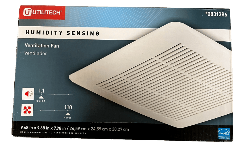
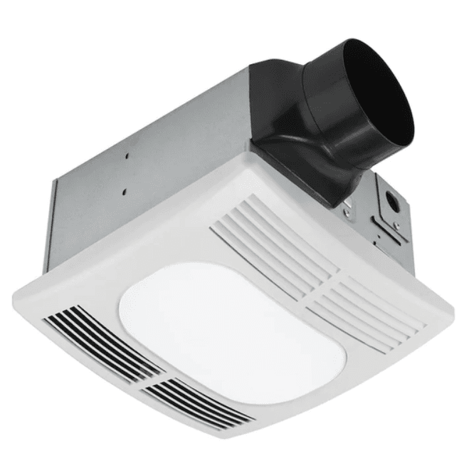
Utilitech 7123 Heater Ventilation Fan
 PACKAGE CONTENTS
 PACKAGE CONTENTS
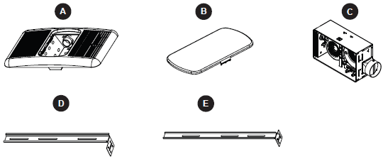
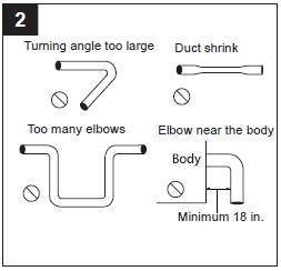
| PART | DESCRIPTION | QUANTITY |
| A | Grille | 1 |
| B | Light lens | 1 |
| C | Fan body | 1 |
| D | 12 in. Suspension bracket | 2 |
| E | 14 in. Suspension bracket | 2 |
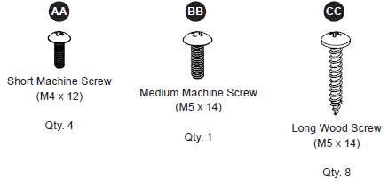
HARDWARE CONTENTS (shown actual size)
PRODUCT SPECIFICATIONS
SPECIFICATIONS | |
| Model No. | 7123-02-L |
| Air direction | Exhaust and circulation |
| V | 120 |
| Hz | 60 |
| Duct diameter (in.) | 4 |
| Noise (sone) | 1.5 sones |
| Power consumption (W) | 1400 |
| Heating element (coil) wattage | 1300 |
| Air delivered at 0.1 in. WG (CFM) | 80 CFM |
IMPORTANT INSTRUCTIONS
- Read all instructions before installing or using this heater.
- Extreme caution is necessary when any heater is used by or near children or invalids and whenever the heater is left operating and unattended.
- Do not operate any heater after it malfunctions. Disconnect power at the service panel and have the heater inspected by a reputable electrician before reusing.
- Do not use outdoors.
- To disconnect the heater, turn the controls to OFF and turn off power to the heater circuit at the main disconnect panel.
- Do not insert or allow foreign objects to enter any ventilation or exhaust opening, as this may cause an electric shock or fire, or damage the heater.
- To prevent a possible fire, do not block air intakes or exhaust in any manner.
- A heater has hot and arcing, or sparking parts inside. Do not use it in areas where gasoline, paint, or flammable vapors or liquids are used or stored.
- Use this heater only as described in this manual. Any other use not recommended by the manufacturer may cause fire, electric shock, or injury to persons.
- SAVE THESE INSTRUCTIONS.
SAFETY INFORMATION
Please read and understand this entire manual before attempting to assemble, operate, or install the product.
- Follow all local safety and electrical codes as well as NEC (National Electrical Code) and OSHA (Occupational Safety and Health Administration).
- This unit must be properly grounded.
- Always disconnect the power supply prior to servicing the fan, motor, or junction box.
- Do not bend or kink the power wires. Protect from sharp edges, oil, grease, hot surfaces, chemicals, or other objects.
- Do not install where the room air temperature will exceed 40ºC (104ºF).
- Do not install over a tub or mount in a shower stall enclosure.
- Do not use it to exhaust hazardous or explosive vapors.
- Do not install in a cooking area.
- Do not install this fan vertically on a wall.
- Use this unit in the manner intended by the manufacturer. If you have any questions, please call the manufacturer (customer service number located on the last page).
- Installation work must be carried out by a qualified person(s) in accordance with all local and safety codes, including the rules for fire-rated construction. For use in non-fire rated installations only.
- Sufficient air supply is required for proper combustion and the exhaustion of gases through the chimney (flue) of fuel-burning equipment to prevent back-drafting. See the standards of NFPA (National Fire Protection Association) and ASHRAE (American Society for Heating, Refrigerating, and Air Conditioning Engineers) and the local building code authorities.
- Exercise care not to damage existing wiring when cutting or drilling into walls or ceilings.
- Fans should always be vented to the exterior and in compliance with local codes.
- Do not use this fan with any solid-state control device such as a dimmer switch. Solid-state controls may cause harmonic distortion, which can cause a humming noise.
- Prior to servicing or cleaning this unit, shut off the power supply at the panel and lock it to prevent the power from being turned on. If the panel cannot be locked, clearly mark the panel with a warning tag to prevent the power from being turned on.
- Do not install in a ceiling with insulation greater than R40. (This is required for installations in Canada only.)
- Ductwork should be installed in a straight line with minimal bends.
- Duct work size must be a minimum of the discharge and should not be reduced. Reducing the duct size can increase fan noise.
- This ventilating bath fan is intended for residential use only in 1-2 2-family dwellings.
- Never place a switch where it can be reached from a tub or shower.
- Make sure that the electric service supply voltage is AC 120 V, 60 Hz.
- Always disconnect the power source before working on or near the unit.
- This unit is designed and tested to be a supplemental heater for use with a timer or a switch. It is not intended to be used as the primary source of heat and is controlled by a thermostat.
- To avoid motor bearing damage and noisy and/or unbalanced impellers, keep drywall spray, construction dust, etc., off the power unit.
- Provide a separate 20-AMP circuit.
- This product is designed for ceiling installation only. Do not mount this product on a wall.
- Install in the ceiling only, at least 6 in. from any wall.
- For greatest efficiency, install heater so heat is directed toward tub or shower area. Avoid directing toward walls or windows.
- Do not install less than 8 ft. (2.4 m) from the floor.
PREPARATION
- Inspect ductwork and wiring before proceeding with installation.
- Before installation, provide inspection and future maintenance access at a location that will not interfere with installation work.
- Remove the ceiling section using the dimensions provided below. Be careful to cut the hole exactly. If the hole is too big, the fan grille will not hide it.
- Determine the distance between your joists.
Dimensions
| DESCRIPTION | LENGTH | WIDTH | HEIGHT |
| Ceiling Opening | 14-5/8 in. | 8-1/2 in. | 5-1/2 in. |
| Housing Dimension | 14-3/8 in | 8-1/4 in. | 5-1/2 in. |
WARNING:
Be careful to cut the hole exactly. If the hole is too big, the fan grille will not hide it.
ASSEMBLY INSTRUCTIONS
Unpacking
Carefully remove the unit from the carton. Remove the foam from the housing. Refer to the Package Contents list on page 3 to verify that all parts are present.
Installing the unit
Installing the fan body in an existing building requires an accessible area (attic or crawl space) above the planned installation location and existing duct and wiring.
CAUTION: Check the area above the installation location to ensure that:
- Duct work can be run, and the area is sufficient for proper ventilation.
- Wiring can be run to the planned location.
- No wiring or other obstructions can interfere with installation.
WARNING:
To reduce the risk of fire, do not store or use gasoline or other flammable vapors and liquids in the vicinity of the heater.
Mounting the fan between the joists
- Insert either the 12 in. suspension brackets (D) or the 14 in. suspension brackets (E) to the duct side and back of the fan body (C), depending on the distance between the joists.
- Insert the fan body (C) between joists. Make sure the fan body is level and perpendicular with the joist, and flush with ceiling surface.
- Allow for the thickness of the ceiling board used in your application. Do not flush mount to joist. Fan body (C) should be flush with the ceiling board.
- Secure the suspension brackets to joists with the long wood screws (CC).
- Secure the suspension brackets to fan body (C) with the short machine screws (AA).

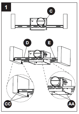
Hardware Used
(AA) Short Machine Screws
(CC) Long Wood Screws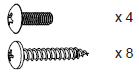
Connecting the duct
CAUTION: All ducting must comply with local and national building codes.
- Snap the damper/duct connector (not included) onto the fan body. Make sure that tabs on the connector lock into housing slots.
- Insert the duct into the duct connector and tape all duct work connections to make them secure and air-tight.
- Do not install the unit where ducts are configured as shown in Figure 2.
- Install the duct with a gradient of 1°~2° to the outside.

Completing the installation
- Insert the plug from the heating unit into the receptacle marked “Heat”, the plug from the fan into the receptacle marked “Vent”, and the plug from the light into the receptacle marked “Light”.
- Install the grille into the fan body using the medium machine screw.
WIRING INSTRUCTIONS
CAUTION
- Make sure the power is switched off at the service panel before starting the installation.
- All electrical connections must be made in accordance with local codes, ordinances, or the National Electrical Code. If you are unfamiliar with methods of installing electrical wiring, secure the services of a qualified electrician.
WARNING:
- This unit must be wired on a separate 20-amp circuit.
- If your house wires do not match these colors, you must determine what each house wire represents before connecting, and you may need to consult an electrical contractor to determine this safely.
- Follow all local electrical and safety codes.
- Never place a switch where it can be reached from a tub or shower.
- Using wire nuts (not included), connect house power wires to fan wires.
- 14 AWG (2.1 mm2) is the smallest conductor that shall be used for branch-circuit wiring. Each power wire (light, fan, heater) must have its own switch to operate independently.
- For supply connections, use wire rated for at least 90ºC.
OPERATING INSTRUCTIONS
CAUTION: Failure to secure the reflector screws may result in a rattling or humming noise.
WARNING: This unit must be properly installed before it is used. Follow instructions for cleaning, user-maintenance, and operations recommended by the manufacturer, such as lubrication or non-lubrication. Any other servicing should be performed by an authorized service representative.
- Turn on the light switch to turn on the light bulb.
- Turn on the vent switch to operate the fan mode.
- Turn on the heat switch to operate the heater mode.
CARE AND MAINTENANCE
Routine maintenance must be done every year.
CAUTION
Make sure the power is switched off at the service panel before servicing the unit.
To replace bulb
- Remove the lens by gently depressing the sides and pulling down. Use bulbs rated up to 60 watts only.
- Allow bulbs to cool before replacing.
To clean the lens and grille
- Remove the lens as explained above. Remove the bulb. Remove screw in center of reflector and lower assembly.
- The grille and reflector are separate units. Unplug the light from the receptacle. Plastic parts can be cleaned with mild, soapy water and dried with a soft cloth.
- Do not use abrasive cloths, steel wool pads, or scouring powders. Never use solvents, thinners, or harsh chemicals for cleaning the fan.
To clean the fan assembly
- Unplug the fan motor cord from the receptacle. Remove retaining screws. Gently vacuum the fan, motor, and interior housing. The motor is permanently lubricated and never needs oiling.
- Fan and motor will swing downward when screw is removed. Support this unit with free hand while removing retaining screw.
To clean the heater assembly
Unplug the heater cord from the receptacle. Loosen retaining screws. Place a screwdriver tip between the outer wall of the housing and the heater exhaust opening. Gently pry outward until the exhaust housing slips off the support tip. Gently vacuum the fan, motor, and interior housing. The motor is permanently lubricated and never needs oiling.
- The unit will swing downward when released. Support with a free hand while prying with a screwdriver.
- Metal and electrical parts should never be immersed in water.
FIVE-YEAR LIMITED WARRANTY
If this product fails due to a defect in materials or workmanship at any time during the first five years of ownership, the manufacturer will replace it free of charge, postage-paid at their option. Simply contact Customer Service at 1-866-994-4148 for replacement information. This warranty does not cover products that have been abused, altered, damaged, misused, cut, or worn. This warranty does not cover use in commercial applications. The manufacturer DISCLAIMS all other implied or express warranties, including all warranties of merchantability and/or fitness for a particular purpose. As some states do not allow exclusions or limitations on an implied warranty, the above exclusions and limitations may not apply. This warranty gives you specific legal rights, and you may have other rights that vary from state to state.
This warranty is limited to the replacement of defective parts only. Labor charges and/or damage incurred during installation, repair, replacement, as well as incidental and consequential damages connected with the above, are excluded. Any damage to this product as a result of neglect, misuse, accident, improper installation, or use other than the purpose shall void this warranty.
REPLACEMENT PARTS LIST
For replacement parts, call our customer service department at 1-866-994-4148, 8 a.m. – 6 p.m. EST, Monday – Thursday, 8 a.m. – 5 p.m. EST, Friday.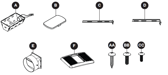
| PART | DESCRIPTION | PART # | PART | DESCRIPTION | PART # |
| A | Grille reflector assembly | BFP-034 | AA | Long wood screw (4) | BFP-043 |
| B | Light lens | BFP-035 | BB | Medium machine screw (1) | |
| C | 12 in. Suspension bracket | BFP-037 | CC | Short machine screw (8) |
| D | 14 in. Suspension bracket | BFP-037 |
| E | Damper | BFP-042 |
| F | Grille assembly | BFP-038 |
For more Manuals by Utilitech, visit ManualsLibraryy
Utilitech 7123 Heater Ventilation Fan-FAQs
Why isn’t my Utilitech ventilation fan working?
There could be several reasons including a faulty power supply, a blown fuse, blocked vents, damaged motor, loose wiring, or simply old age. First, check if the fan is properly connected and receiving power.
Who manufactures Utilitech bathroom fans?
Utilitech products, including bathroom fans, are sold exclusively by Lowe’s. These fans are often manufactured by Broan-NuTone, LLC, based in Hartford, Wisconsin, USA.
How do bathroom heater fans function?
Bathroom heater fans typically use compact, energy-efficient infrared heat lamps to warm small spaces. They also help reduce humidity more effectively than fans alone, which is useful in bathrooms with frequent use.
How should I vent my bathroom fan?
If your ceiling-mounted fan is in an attic-accessible area, you can vent it through a gable wall or the roof. Avoid venting into the attic or through soffit or ridge vents, as this can cause moisture problems.
What causes a fan to make noise or overheat?
Loud noise or overheating may result from blocked air vents, dust buildup, or poor air circulation. Make sure the fan and vents are clean and unobstructed.
Why is the ventilation in my bathroom poor?
Poor airflow may be caused by blocked vents or furniture obstructing the air path. Check for closed or blocked vents and clean the area around them. If the fan still underperforms, its motor could be at fault.
What does CFM mean in bathroom fans?
CFM stands for Cubic Feet per Minute, which measures how much air the fan moves. For bathrooms up to 45 square feet, a 50 CFM fan is usually sufficient.
How does a ventilation fan work?
A ventilation fan removes stale, humid air and helps draw in fresh air from outside, improving indoor air quality and reducing moisture buildup.