Victron Energy 7.3kW EV Charging Station
Safety Instructions
- Please read the safety instructions below before using the EV Charging Station to avoid risks of fire, electric shocks, and personal injuries or equipment damage.
- Installation and adjustments must be made by qualified personnel only. To reduce the risk of electric shock, do not perform any servicing other than that specified in the operating instructions unless you are qualified to do so.
- For electrical work, follow the local national wiring standard, regulation, and these installation instructions. Connection to the mains supply must be in accordance with the national regulations for electrical installations.
- This product is designed and tested in accordance with international standards.
- The equipment should be used for its designated application only and in accordance with the specified operating parameters.
Description and features
Description
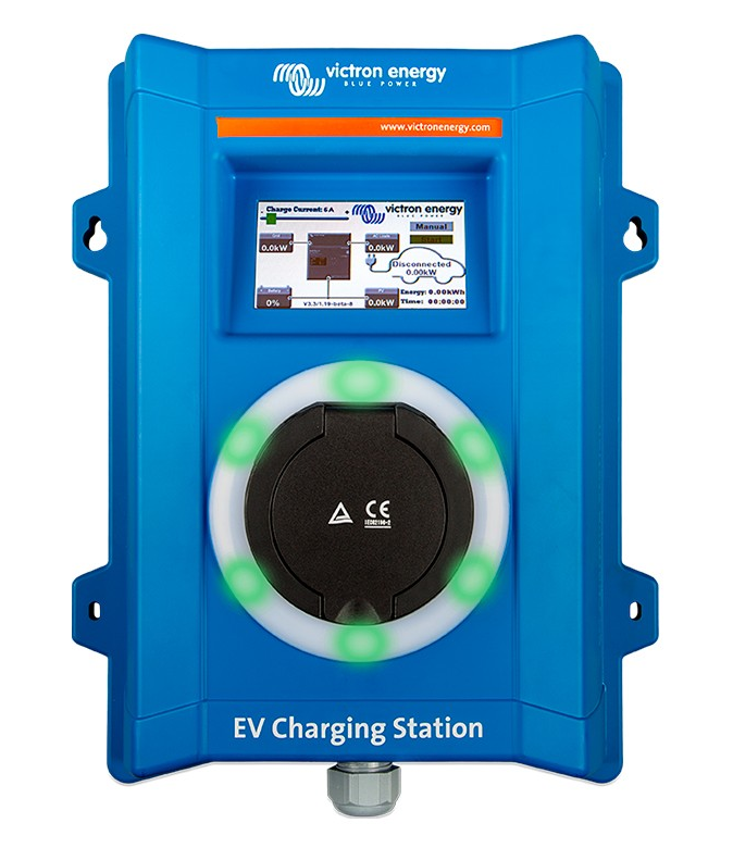
- The EV Charging Station, with its three-phase and single-phase charging capabilities, integrates seamlessly into the Victron environment with its GX device connection via WiFi and enables easy operation and control via Bluetooth and the VictronConnect App. It delivers a maximum of 22kW AC in three-phase or 7.3kW in single-phase mode. A built-in 4.3-inch LCD touch screen enables easy monitoring and control.
- Not only does this EV charging station fully integrate with a Victron Energy GX device and VRM, but if you have solar, it can also be set up to allow excess energy from the sun to directly charge your vehicle once certain parameters are met. See the EV Charging Station Setup [14] chapter for details.
- The tough plastic enclosure is designed to withstand harsh weather and can be mounted inside or outside.
- A programmable RGB light ring around the charging port (type 2 EV charging plug) allows for quick determination of the device state and can be programmed from the integrated web interface to display different light effects based on the current state (disconnected, charging, charged, etc.).
Features
Three operation modes:
Automatic mode to ensure maximum PV system efficiency
Thanks to the seamless integration of the EV Charging Station with the rest of the Victron installation, it detects when surplus power is available and uses only this power to charge the vehicle. Note that this mode requires a GX device in your system, and communication between the GX device and EVCS must be enabled. For details, see chapter EV Charging Station setup [14]. Instead of losing surplus energy when the batteries are full and, for example, feeding it back into the grid at a lower price, the energy is stored in the EV battery.
- Seamless integration into the Victron installation
- Detects when excess power is available and uses only that to charge the vehicle before exporting it to the grid
- Ensures maximum PV efficiency
- Battery-powered algorithm (used by default) for automatic mode ensures that automatic mode works even when off-grid.
How does it work?
The EVCS will automatically start charging when the vehicle is connected and the following conditions are met:
- The current state of charge is above the ‘Start charging at backup battery SoC (%) value.
- There is enough excess solar power available, with excess solar power calculated as follows:
- Excess solar power = Total PV production – AC loads (without car consumption) = 1380W (230V x 6A). In the example above, the Min charge current (from 6A) value has been set to 6A. The required excess solar power
Increases accordingly if a higher value is set for the Min charge current (from 6A). Please see the chapter EV Charging Station setup [14] for details on both parameters.
- Excess solar power = Total PV production – AC loads (without car consumption) = 1380W (230V x 6A). In the example above, the Min charge current (from 6A) value has been set to 6A. The required excess solar power
Manual mode to configure the output current
Manual mode allows configurable output current between 6 and 32A. The charging power is controlled in several ways:
- By using the slider on the LCD touch screen
- By using the web interface via a web browser
- From a GX device touch screen, like the GX Touch 50 & GX Touch 70
- From the Remote Console
- By using the Controls on the Dashboard of our VRM Portal (requires a GX device)
- Via Bluetooth and the VictronConnect App
It allows charging to be started or stopped manually when an EV is connected to the charging station, regardless of PV production.
Scheduled mode to allow automatic charging at custom time intervals
The Scheduler allows charging at different time intervals, for example, at certain times during the night when grid energy is cheaper. In addition to the start and end time, various parameters such as charging current and interval can be defined. The EVCS will then start charging according to the scheduler settings.
WiFi Communication, WiFi 802.11 b/g/n for configuration, control, and monitoring: The internal WiFi module can be configured in Access Point mode or Station mode, for first setup, control, and monitoring.
Bluetooth communication via VictronConnect
Integrated Bluetooth capability enables easy monitoring and control of the EV Charging Station via VictronConnect from any mobile device, such as an iPhone, iPad, or Android phone. For more details, see the VictronConnect setup, configuration, and operation [23] chapter.
Integration with GX devices
Control and monitor the EV Charging Station from a GX device such as the Cerbo GX and the Remote Console. For more details, see the GX device setup, configuration, and operation [20] chapter.
Integration with VRM
Several options are available in the VRM Portal:
- Real-time reports
- Custom reports for configurable time periods
- Advanced functions such as remote firmware updates
- Change mode and charge current via Dashboard Controls on the VRM Portal and start/stop charging.
Control and monitoring are also possible via the VRM App (download from App Store or Google Play) and VRM App Widgets directly from the home screen of a mobile device.

LCD Touch Screen
Built-in 4.3″ LCD touch screen for monitoring and control directly from the charging station.
Light Ring for fast viewing of the device state
It also has a fully programmable RGB light ring around the charging port, which can be used to quickly determine the status of the device even from a distance. It can be programmed via the web interface to display different light effects depending on the current state (disconnected, charged, loaded, etc.).
What’s in the box?
- EV Charging Station with a supplied 28mm nylon cable gland for power cables up to 19mm in diameter.
Installation
This product may only be installed by qualified personnel (licensed electrician). It is suitable for wall mounting or pole mounting (vertical surface). In all cases, the surface should be solid and flat.
Installation steps:
- Remove the black backing plate by unscrewing the 8 screws.
- Mark the wall where it should be mounted using the removed backing plate as a template.
- Drill 4 holes with wall plugs ready for installation.
- Measure a suitable location and drill through the wall for the cable (when the main supply cable comes from inside the building).
- Label each cable and pass it through the wall, the nylon gland, the grommet, and into the charging station.
- Terminate the cable ends with ferrules and connect to the relevant points.
- If this is a single-phase installation, use L1, neutral, and earth connections.
- Tighten the nylon gland around the cable.
- Reattach the black plate to the charging station and tighten the 8 screws.
- Mount the station on the wall.
System example

This system displays all available options, specifically:
- All solar types: AC PV on AC input, AC PV on AC output, and DC PV
- EV Charging Station on the AC input or the AC output of the inverter/charger
- Single-phase or three-phase.

Setup
First setup
First setup via WiFi access point
The charging station broadcasts its own WiFi access point as soon as the charging station is powered for the first time. The following steps describe the first setup to prepare the charging station for operation.
Connect to the WiFi access point:
- Scan the QR Code on the internal label.
- Or go to the WiFi menu of your mobile device or laptop and manually add the access point that automatically broadcasts its SSID. SSID and WiFi key are noted on a sticker inside the case.
- Or scan the QR code shown on the display during the first setup phase. Note that after the first setup, another QR code will appear on the display, linking to the Victron website.

Once connected to the access point, enter the default IP address 192.168.0.1 into a web browser. The First setup process will then start:
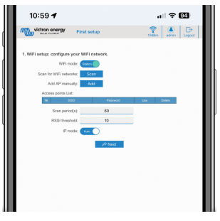
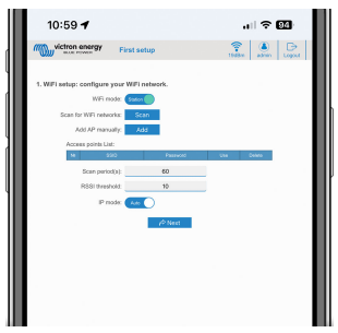
WiFi setup: Configure the WiFi network by choosing the WiFi mode
- Access point: The unit creates its own WiFi access point. This is either for setting up the unit or, in the absence of a separate WiFi network, including a GX device. Set SSID, IP address, and Netmask according to your needs.
- Set SSID, IP address, and Netmask according to your needs.

- Set SSID, IP address, and Netmask according to your needs.
- Station: Connects the device to a local WiFi network that includes other Victron devices like a GX device or VRM.
- Change the WiFi mode from AP to Station.

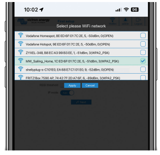
- Click the Scan button (the scan period and RSSI threshold apply) to search for other WiFi networks or add manually a known AP by clicking the Add button. Note the WiFi standards: 802.11 b/g/n (2.4Ghz only).
- Tick the network you wish to connect to and then click Apply.

- In the Password box, enter the external WiFi password and click Next.
In case you need a static IP rather than DHCP, change the IP mode button to Manual and fill in the static IP address, Mask, Gateway, and DNS.
- Change the WiFi mode from AP to Station.
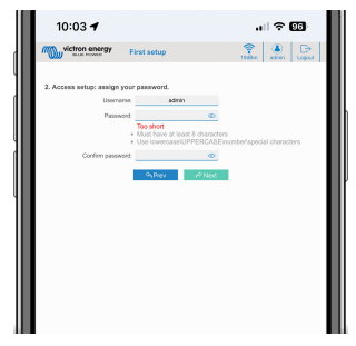
- Access setup:
- Click into the Username field and type in your own username. The default username is ‘admin’.
- Click into the Password field and change the password to a new one with at least 8 characters, containing lower, upper, and special characters. The default password is printed on the sticker inside the unit.
- Confirm your new password.
- Click Next.

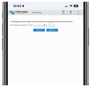
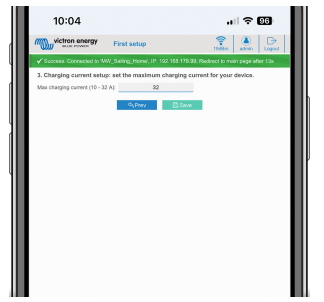
- Charging current setup:
- Set the maximum charging current (10 – 32A).

- Set the maximum charging current (10 – 32A).
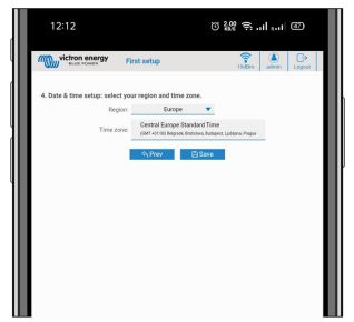
- Time zone setup and first setup completion:
- Select the time zone region and set the time zone. Daylight saving time is processed automatically. If UTC is selected as the region, it is necessary to enter the correct offset. Valid time format: +hh: mm or -hh: mm – Example: +02:00 or -01:00

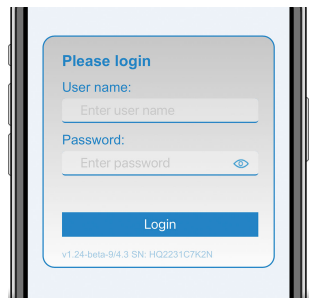
- Click Save to apply all settings. The system restarts, and the login page of the web interface is displayed

- Log in with your credentials that you entered under 3.

- The main page is then displayed, and the EV Charging Station is ready for use.
- Select the time zone region and set the time zone. Daylight saving time is processed automatically. If UTC is selected as the region, it is necessary to enter the correct offset. Valid time format: +hh: mm or -hh: mm – Example: +02:00 or -01:00
EV Charging Station setup
After initial setup, set up the EVCS according to your needs. To do this, connect to the web interface and click on the Settings tab for further setting options. The main page options are explained in the main page [17] chapter.
Six subtabs will appear:
- Networks tab: See the Networks menu [18] chapter.
- General tab: Provides setting options for the charger, GX device communication, display, time zone, and device name
The main page
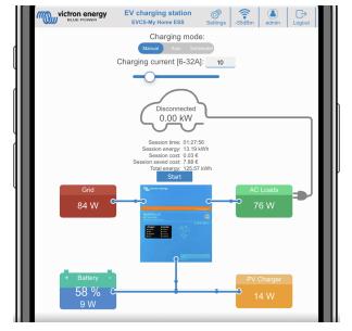
The main page of the web interface provides control and monitoring elements for the EV Charging Station. These are from top to bottom:
- Charging mode switch: Change the charging mode to manual, auto, or scheduled.
- Charging current slider: Adjust the charging current.
- Start/Stop button: Start or stop charging when in manual mode. Note that after pressing the stop button, first the charging current is reduced to a minimum, and only then the contactor opens (with a delay of 2 seconds).
- Session statistics and an animated graphical overview to see the charging progress at a glance.
Access menu
In the Access menu, you can choose your own username and password (strongly recommended). Note that you will be prompted to change the password during the initial setup. To change the username and password:
- Click into the Username field and type in your own username. The default username is ‘admin’ (without apostrophe).
- Click into the Password field and change the password to a new one with at least 8 characters, containing lower, upper, and special characters. The default password is printed on the sticker inside the unit.
- Confirm your new password.
- Click Next.
GX device setup, configuration, and operation
Modbus TCP activation
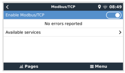
The EV Charging Station communicates with the GX device via Modbus TCP. This must first be activated in the GX device and is a mandatory step.
- In the GX device, go to Settings → Services → Modbus TCP and enable Modbus TCP.
Activate the charging station in the Modbus TCP/UDP menu
This step is only required if it is an EV Charging Station that has not already been connected to the GX device, AND the GX device has firmware version 3.12 or higher.
For devices that were already connected to the GX device before a GX firmware update to Venus OS 3.12, this step is not necessary. These units are activated automatically.
- In the GX device, go to Settings → Modbus TCP/UDP → Discovered devices and activate the EVCS.

VictronConnect setup, configuration, and operation
Setup
The following steps are necessary to successfully connect to the EV Charging Station via Bluetooth and VictronConnect:
- Make sure Bluetooth is enabled in your EVCS. In case Bluetooth is disabled, see the Networks menu [18] chapter for details on enabling Bluetooth.
- Download and install the VictronConnect app from the App Store or Google Play.
- Open VictronConnect and scroll through the list of devices for the EVCS.
- Tap on it to launch the pairing dialog. Enter the pairing code, which is either 000000 or a unique number on the sticker inside the housing.
- If the pairing was successful, the EVCS overview page is displayed.
Troubleshooting
CP Line Calibration
What is CP?
CP is the control pilot signal (line) inside each Type 2 charger connector. It is a bi-directional communication line that enables communication between the charging station and the EV. Among other things, the charging station informs the EV of the
maximum charging current available. At the same time, the EV informs the charging station about its status, for example, whether the EV is connected or whether it is currently charging.
Why is CP line calibration necessary?
Due to differences in cable length and manufacturer, as well as deviations in the ratings of electronic components, the CP signal may show deviations. The CP calibration takes the signal deviation into account and adjusts the signal values to the required ranges.
When does the calibration of the CP line have to be carried out?
There are several reasons for a CP line calibration. The most important are:
- The EV is connected to the EVCS via the charging cable, but still reports a disconnected state
- When charging the EV, the EVCS frequently switches between the ‘charging’ and ‘charged’ states
- The EVCS does not start charging after connecting the vehicle because it cannot detect the correct state after connection.
How is a CP line calibration carried out?
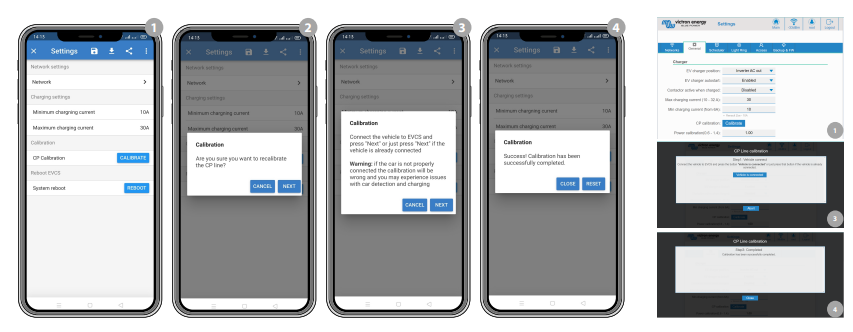
The CP calibration can be done via the web interface (Settings → General → Charger → CP calibration or via VictronConnect (Settings page). The procedure is as follows:
- Press the calibration button
- Connect the EV to the EVCS and then tap on Next in VictronConnect
- Press the ‘Vehicle is connected’ button to confirm that the EV is indeed connected to the EVCS (or tap on Next in VictronConnect)
- Wait until the EVCS has completed the calculation. Once the calibration is complete, a message is displayed indicating that the calibration was successful.
Maintenance
The EV Charging Station does not require specific maintenance.
Technical specification

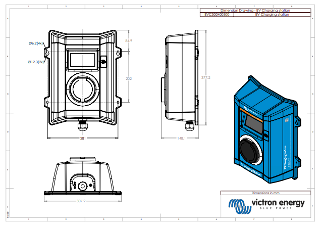
Dimensions
FOR MORE MANUALS BY Victron Energy, VISIT MANUALSLIBRARYY
Victron Energy 7.3kW EV Charging Station-FAQs
Q1. What are the basic requirements for installing an EV charging station?
An EV station needs proper cabling, power lines (such as 33/11 kV), and enough space for safe vehicle entry, exit, and charging operations.
Q2. How does the Victron Energy 7.3kW EV charger work?
It converts AC power from the grid into DC to charge the vehicle’s battery, managing voltage and current to ensure safe and efficient charging.
Q3. How long does it take to charge an EV with a 7.3kW charger?
On average, a 60 kWh battery takes around 7–8 hours to charge fully. Many users prefer topping up, which adds significant range in shorter sessions.
Q4. How much range is added per hour of charging at 7.3kW?
A 7.3kW station typically adds about 25–30 miles (40–50 km) of driving range per hour, depending on the vehicle.
Q5. What voltage and current are needed for this charging station?
It generally uses 230V AC power and delivers around 32 amps, suitable for most residential and commercial EV charging setups.
Q6. Is it safe to charge an EV in the rain with this unit?
Yes. The Victron charger is designed with weatherproof protection, making it safe for outdoor charging even in rainy conditions.
Q7. How many types of EV chargers exist, and where does this fit?
There are three main types: Level 1 (120V), Level 2 (208–240V), and DC fast charging. The Victron 7.3kW is a Level 2 charger.
Q8. What is the lifespan of an EV charging station like this?
A well-maintained charging station typically lasts 10–15 years, while heavy-duty units like Victron can exceed two decades.
Q9. What are common problems with Victron chargers?
Issues may include wiring errors, incorrect settings, or external system faults. Most can be fixed by checking connections or resetting the unit.


