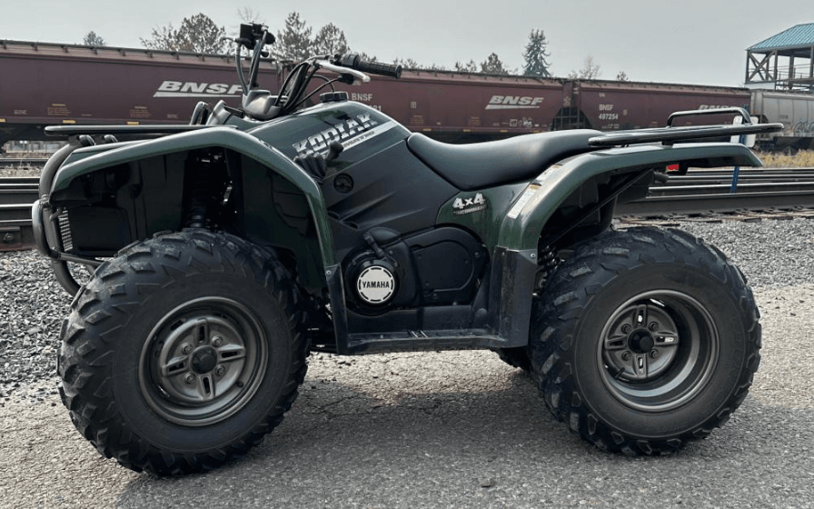
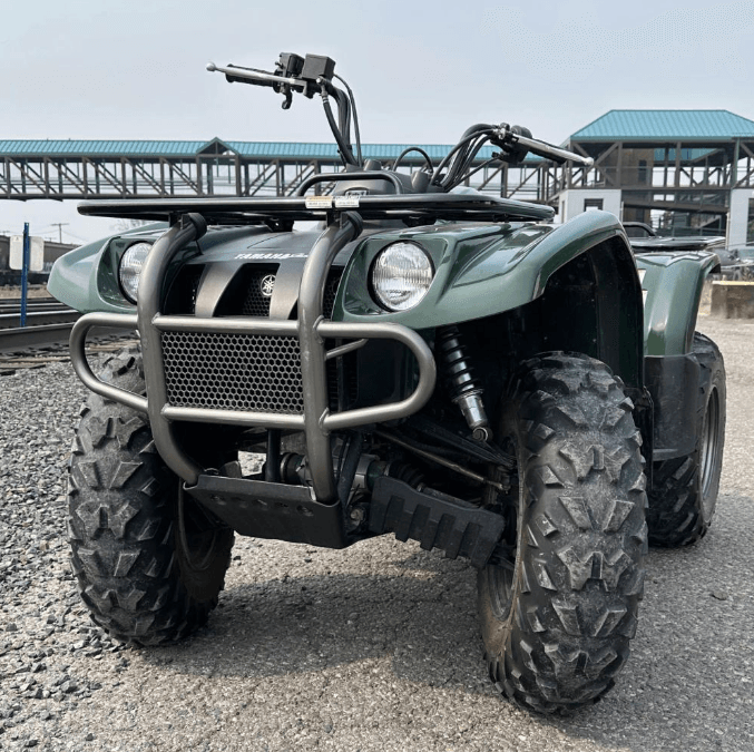
Yamaha YFM400FW Kodiak 400 ATV Bike
SPECIFICATIONS
GENERAL SPECIFICATIONS
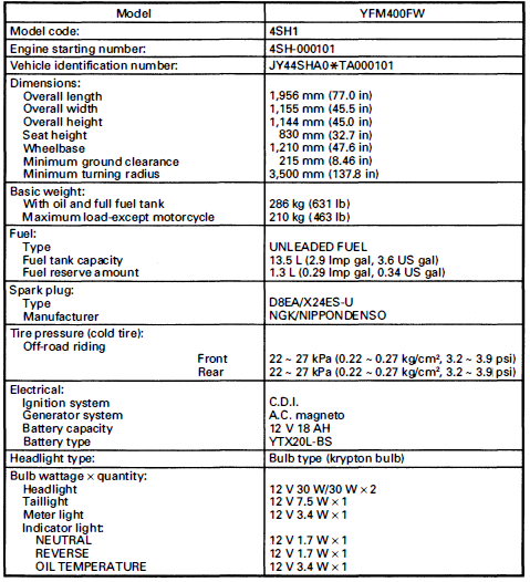
MAINTENANCE SPECIFICATIONS
ENGINE
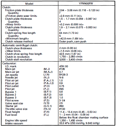
MAINTENANCE SPECIFICATIONS
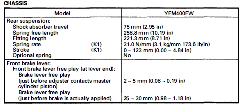

ELECTRICAL
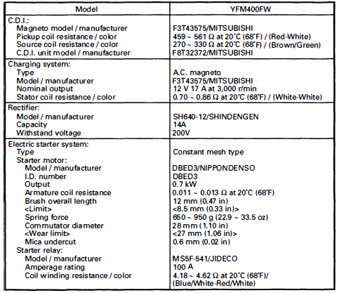
EXCLUSIVE SPECIFICATIONS
The following specifications are exclusive to the countries listed below. For specifications other than those below, please refer to the General and maintenance specifications.
For Canada

For Europe
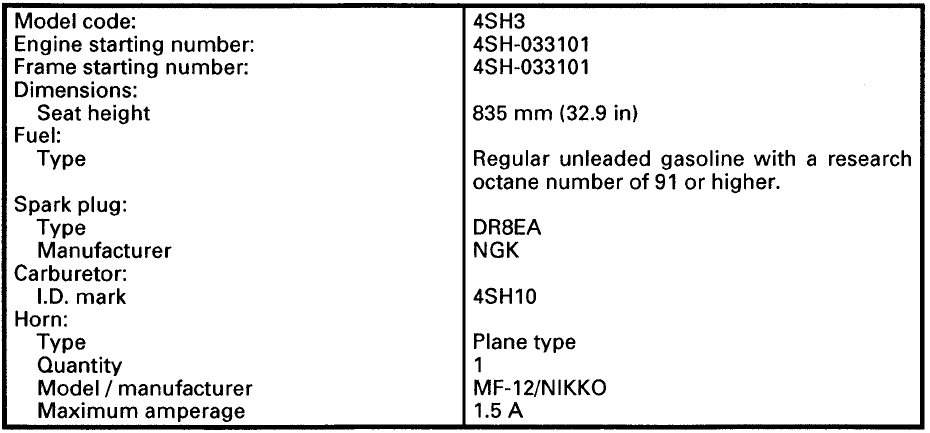
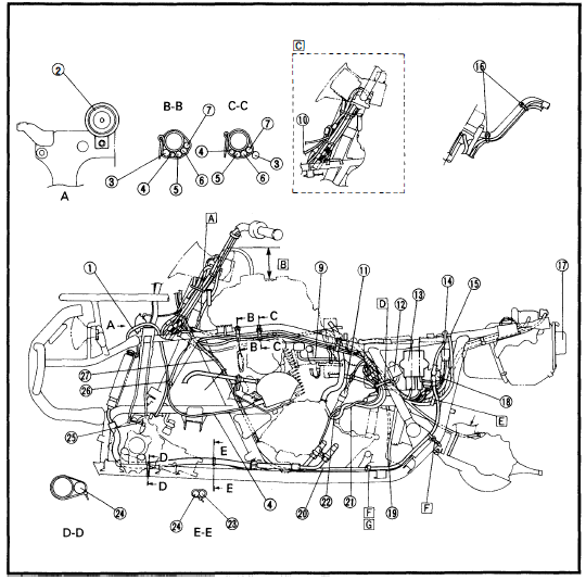
CABLE ROUTING
- Rear brake switch
- Rear brake cable
- Terminal (option)
- Front brake hose
- Throttle cable
- Band
- Horn switch (for EUR, OCE)
- Handlebar switch
- Speedometer cable
- Speedometer lead
- Main switch lead
- Indicator light leads
- Handlebar switch lead
- Front brake switch lead
- Horn switch lead (for EUR, OCE)
- Breather hose
- Brake pipe
- Clamp
- Clip
- A. Insert the breather hose into the hole of the handlebar protector.
- B. Clamp the speedometer lead, main switch lead, indicator light lead, handlebar switch lead, front brake switch lead, and horn switch lead.
- C. Clamp the speedometer cable, front brake switch lead, handlebar switch lead, indicator light lead, main switch lead, and horn switch lead.
- D. Pass the speedometer cable, rear brake cable, and throttle cable in order from the inside.
- E. Pass the throttle cable under the brake hose.
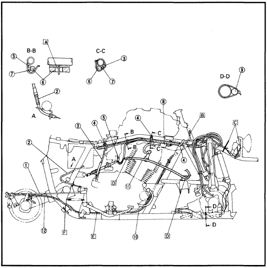
- Breather hose (front brake)
- Horn (for EUR, OCE)
- Throttle cable
- Select lever control cable
- Air bent hose
- Breather hose (rear final gear case)
- Breather hose (rear brake)
- Fuel tank breather hose
- Fuel hose
- Carburetor heater lead
- Thermo unit
- Fan motor control unit
- COi unit
- Battery positive lead
- Battery negative lead
- Band
- Taillight
- Starter relay
- Carburetor overflow hose
- Starter motor lead
- Neutral switch lead
- COi magneto lead
- Oil cooler hose 2
- Oil cooler hose 1
- Breather hose (differential gear case)
- Clamp
- Rear brake cable
- A. Pass the air vent hose, breather hose (rear brake), and breather hose (rear final gear case) through the bracket hole.
- B. 120 mm (4.72 in)
- C. Option
- D. Clamp the COi magneto leads, neutral switch lead, reverse switch lead, wireharness, and fan motor control unit lead.
- E. Clamp the wire harness and battery negative lead.
- F. Clamp the starter motor lead.
- G. Pass the starter motor lead outside of the front drive shaft protector.
- H. Pass the rear brake cable through he guide.
CABLE ROUTINE
- Brake rod
- Select lever control cable
- Speedometer cable
- Band
- Carburetor heater (option)
- Wireharness
- Carburetor heater lead (option)
- Ignition coil
- Oil cooler hose 2
- Starter motor lead
- Select lever control cable 1
- Rear brake cable
- A. White taped
- B. To the speedometer
- C. Clamp the headlight lead.
- D. Pass the select lever control cable 1 through the guide.
- E. Clamp the rear brake cable.
- F. Pass the rear brake cable over the fender stay.
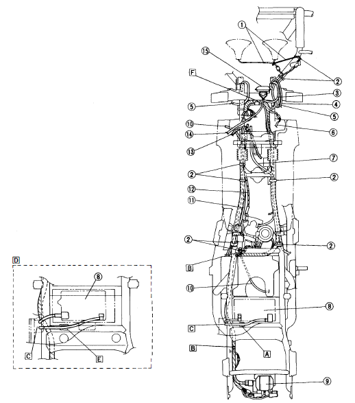
- Headlight lead
- Band
- Breather hose (fan motor)
- Breather hose (bearing housing)
- Breather hose (front brake)
- Terminal lead (option)
- Speedometer cable
- Battery
- Rectifier/regulator
- Select lever control cable 2
- Air vent hose
- Throttle cable
- Rear brake cable
- Horn switch lead (for EUR, OCE)
- Horn (for EUR, OCE)
- A. Pass the positive battery lead through the guide.
- B. Clamp the wire harness.
- C. Pass the battery lead through the fender hole.
- D. For OCE
- E. Pass the battery negative lead through the guide.
- F. White taped
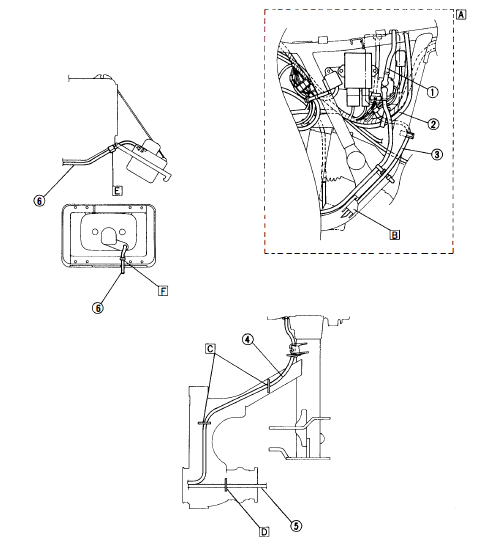
- Battery positive lead
- Battery negative lead
- Battery breather hose
- Breather hose (rear brake)
- Breather hose (rear final gear case)
- Taillight lead
- A. For OCE
- B. Pass the battery breather hose through the guide.
- C. Pass the breather hose (rear brake) through the guide.
- D. Pass the breather hose (rear final gear case) through the guide.
- E. Clamp the taillight lead.
- F. Pass the taillight lead through the guide.
SEAT, CARRIERS, FENDERS, AND FUEL TANK
PERIODIC INSPECTION AND ADJUSTMENT OF SEAT, CARRIERS, FENDERS, AND FUEL TANK REMOVAL
- Place the machine on a level place.
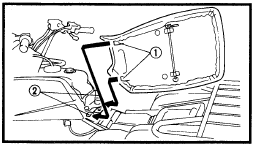
- Remove:
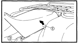
- Seat

- Seat
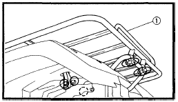
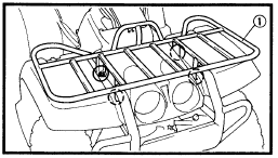
- Remove:
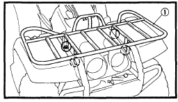
- Front carrier

- Front carrier
- Disconnect:
- Headlight couplers

- Headlight couplers
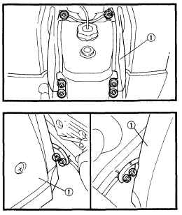
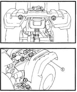
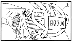
- Remove:
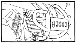
- Front bumper
- Remove
- Front Fender

- Front Fender
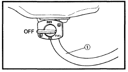
- Turn the fuel cock lever to “OFF”.
- Disconnect:
- Fuel hose

- Fuel hose
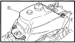
- Remove:
- Fuel tank

- Fuel tank
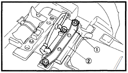
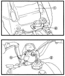
- Remove:
- Battery holder
- Disconnect:
- Battery leads
- Battery breather hose (for OCE)

- Remove:
- Battery
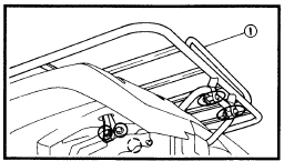
- Remove:
- Rear carrier

- Rear carrier
- Remove:
- Rear fender

- Rear fender
INSTALLATION
Reverse the “REMOVAL” procedure. Note the following points.
- Install:
- Fuel tank CD

- Fuel tank CD
- Install:
- Rear fender
- Battery
- Battery holder
- Connect:
- Battery leads
- Battery breather hose (for OCE)
- Install:
- Rear carrier

- Rear carrier
- Install:
- Front fender
- Front bumper

- Install:
- Front carrier

- Front carrier
- Install:
- Seat

- Seat
GENERAL INFORMATION MACHINE IDENTIFICATION
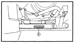
VEHICLE IDENTIFICATION NUMBER (FOR USA AND CON)
- The vehicle identification number CD is stamped into the left side of the frame.
- NOTE: The vehicle identification number is used to identify your machine and may be used to register your machine with the licensing authority in your state.

- NOTE: The vehicle identification number is used to identify your machine and may be used to register your machine with the licensing authority in your state.
FRAME SERIAL NUMBER (EXCEPT FOR USA AND CON)
- The frame serial number CD is stamped into the left side of the frame.
- NOTE: The first three digits of these numbers are for model identification; the remaining digits are the unit production number.

- NOTE: The first three digits of these numbers are for model identification; the remaining digits are the unit production number.
ENGINE SERIAL NUMBER
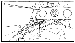
- The engine serial number CD is stamped into the right side of the engine.
- NOTE: The first three digits of these numbers are for model identification; the remaining digits are the unit production number.

- NOTE: The first three digits of these numbers are for model identification; the remaining digits are the unit production number.
IMPORTANT INFORMATION: PREPARATION FOR REMOVAL
- Remove all dirt, mud, dust, and foreign material before removal and disassembly.
- Use proper tools and cleaning equipment. Refer to “CHAPTER 1. GENERAL INFORMATION-SPECIAL TOOLS” section.
- When disassembling the machine, keep the mated parts together. This includes gears, cylinders, pistons, and other parts that have been “mated” through normal wear. Mated parts must be reused as an assembly or replaced.
- During the machine disassembly, clean all parts and place them in trays in the order of disassembly. This will speed up assembly time and help assure that all parts are correctly reinstalled.
- Keep away from fire.
ALL REPLACEMENT PARTS
- We recommend using Yamaha genuine parts for all replacements. Use oil and/or grease recommended by Yamaha for assembly and adjustment.
GASKETS, OIL SEALS, AND O-RINGS
- AII gaskets, seals, and O-rings should be replaced when an engine is overhauled. All gasket surfaces, oil seal lips, and O-rings must be cleaned.
- Properly oil all mating parts and bearings during reassembly. Apply grease to the oil seal lips.
LOCK WASHERS/PLATES AND COTTER PINS
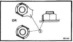
- AII lock washers/plates G) and cotter pins must be replaced when they are removed. Lock tab(s) should be bent along the bolt or nut flat(s) after the bolt or nut has been properly tightened.

BEARINGS AND OIL SEALS
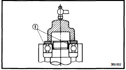
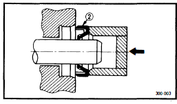
- Install the bearing(s) G) and oil seal(s) with their manufacturer’s marks or numbers facing outward. (In other words, the stamped letters must be on the side exposed to view.) When installing oil seal(s), apply a light coating of lightweight lithium-based grease to the seal lip(s). Oil the bearings liberally when installing.


ENGINE ASSEMBLY AND ADJUSTMENT
Crankcase
- Crankcase assembly
- Crankcase ventilation hose
- Dowel pin
- Dowel pin
- Copper washer
- Stopper plate
- Hexagon socket head screw
- Middle gear case
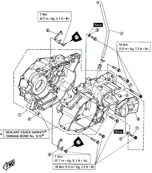
ENGINE ASSEMBLY AND ADJUSTMENT
SHIFTER AND OIL PUMP Shifter
- Bolt (shift cam #2)
- Plain washer
- Spring
- Ball
- Shift shaft
- Plain washer
- Oil seal
- Pan head screw
- Washer
- Segment
- Straight key
- Bolt (stopper lever)
- Stopper lever
- Spring
- Bolt
- Plain washer
- Return spring
- Lever (outside)
- Collar
- Lever (inside)
- Clevis pin
- Plain washer
- Pin
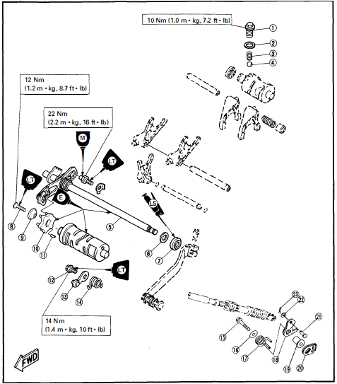
Oil Pump
- Union bolt
- Copper washer
- Oil pipe
- Oil pump assembly
- Oil pump-driven gear
- Pin
- Pan head screw
- Pan head screw
- Pin
- Gasket
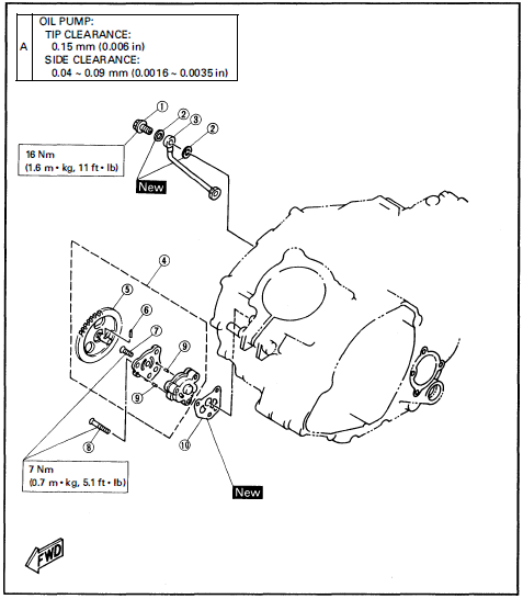
CRANKCASE COVER (RIGHT), SHIFT GUIDE, AND OIL PIPE
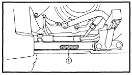
- Dip stick
- O-ring
- Crankcase cover (right)
- Copper washer
- Oil seal
- Bearing
- Stopper plate
- Crankcase cover gasket
- Dowel pin
- O-ring
- Adjust bolt
- Spring
- Release lever (clutch)
- Shift guide #2
- Pawl holder
- Shift guide #1
- Shaft
- Plain washer
- Bearing
- Stopper bolt
- Shift shaft
- Oil strainer
- Spring
- O-ring
- Drain bolt
- Copper washer
- Oil pipe
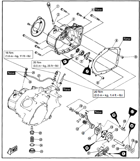
cylinder and cylinder head
- Spark plug
- Tappet cover (intake)
- O-ring
- Tappet cover (exhaust)
- Cylinder head
- Bearing retainer
- Lock washer
- Side cover
- Cylinder
REAR SHOCK ABSORBER AND SWINGARM
REMOVAL
- Remove:
- Seat
- Rear carrier
- Rear fender
Refer to the “SEAT, CARRIERS, FENDERS AND FUEL TANK” section in CHAPTER 3.
- Remove:
- Rear wheels
- Rear brake drum
- Rear wheel hub
- Rear axle
Refer to the “REARAXLE/REARFINAL GEAR AND REAR DRIVE SHAFT-REMOVAL” section in CHAPTER 6.
- Remove:
- Brake shoe plate
Refer to the “REAR BRAKE” section.
- Brake shoe plate
- Remove:
- Trailer hitch bracket
- Rear final gear assembly
Refer to the “REAR AXLE/REAR FINAL GEAR AND REAR DRIVE SHAFT-REMOVAL” section in CHAPTER 6.
- Remove:
- Muffler
Refer to the “ENGINE REMOVAL” section in CHAPTER 4.
- Muffler
ELECTRICAL STARTING SYSTEM
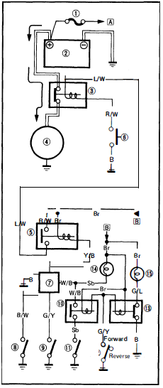
STARTING CIRCUIT OPERATION
The starting circuit on this model consists of the starter motor, starter relay, neutral switch, starting circuit cut-off relay, front stop switch, neutral relay, COi unit, and reverse switch. If the main switch is on and the “ENGINE STOP” switch is RUN, the starter motor can be operated only if:
- The transmission is in neutral (the neutral switch is on) and the select lever is in forward (the reverse switch is on).
- Pull in the front brake lever (the front stop switch is ON).
- NOTE: The starter motor can be operated irrespective of the engine stop switch (“OFF” or “RUN”). However, the engine can be started if the engine stop switch is set to “RUN”.
- The starting circuit cut-off relay prevents the starter from operating when the transmission is in gear or the select lever is in reverse, and the front brake lever is free. In this instance, the starting circuit cut-off relay is off so that current cannot reach the starter motor.
- Fuse
- Battery
- Starter relay
- Starter motor
- Starting circuit cut-off relay
- “START” switch
- CDI unit
- “ENGINE STOP” switch
- Front stop switch
- Neutral relay
- Neutral switch
- Reverse switch
- Reverse relay
- “NEUTRAL” indicator light
- “REVERSE” indicator light
- A. TO MAIN SWITCH
- B. FROM MAIN SWITCH
ELECTRICAL STARTING SYSTEM
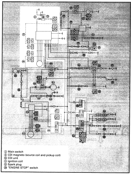
TROUBLESHOOTING
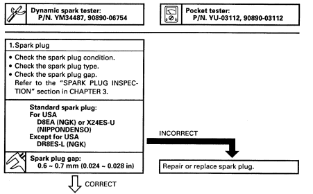
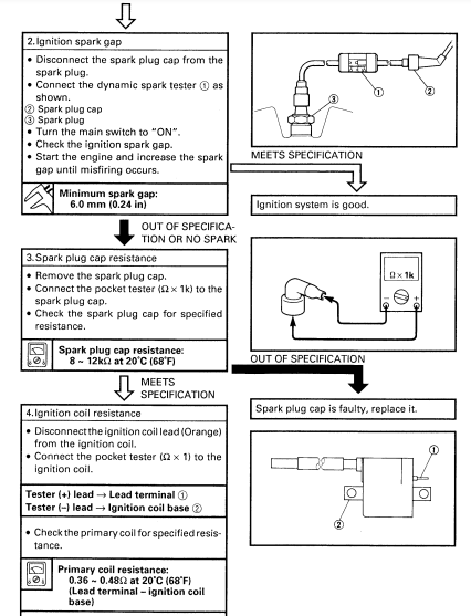
STARTER MOTOR DOES NOT OPERATE.
Procedure Check:
- Fuse
- Battery
- Starter motor
- Starter relay
- Main switch
- “START” switch
- Starting circuit cut-off relay
- “ENGINE STOP” switch
- Neutral switch
- Neutral relay
- Reverse switch
- Front stop switch
- Wiring connection (entire electric starting system)
For more manuals by Yamaha, visit ManualsLibraryy

