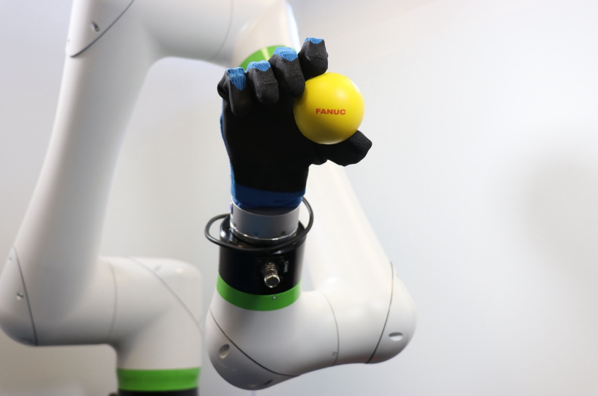
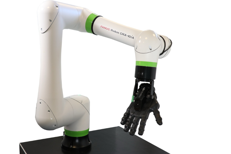
qbrobotics Fanuc CRX Robot SoftHand
Dear customer
Thank you for purchasing our product.
The present document provides information to the best of our knowledge at the time of publication. This document could present differences from the product, and it is subject to changes without notice: the latest version is available on our webpage www.qbrobotics.com. qbrobotics s.r.l. does not assume any responsibility for errors or omissions. In no case, qbrobotics s.r.l. will be responsible for any loss, problems, or damages to persons or property arising from the use of this document. The qb® logo and qbrobotics® are registered trademarks of QB Robotics s.r.l. In the following, the indications of (R) are omitted.
Preface
Using this document
Please check that the document release date is before the product purchase date. The documentation must always be complete and in a perfectly readable state. Keep the document accessible to the operating and, if necessary, maintenance personnel at all times. Pass the document to any subsequent owner or user of the product.
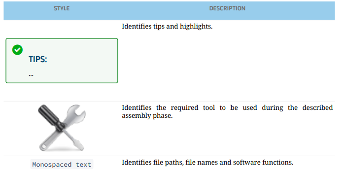
Symbols and conventions

Kit content
The kit consists of:
- N.1 qb SoftClaw;
- N.1 ISO 9409-1-50-4-M6 tool flange adapter;
- N.1 0.3m direct wrist connection cable for compatible robots only;
- N.1 main cable of 3m;
- N.1 USB to RS-485 converter with extension cord;
- N.1 USB flash drive with user documents and applications;
- N.1 cylindrical pin EN ISO 8734 A d6x14 h6;
- N.4 metrical screws EN ISO 4762 M6x10;
- N.8 metrical screws EN ISO 10642 M3x8;
- N.1 2 mm Allen hex key;
- N.1 5 mm Allen hex key.
Optionals:
- 24 VDC power supply unit with cables;
- ISO 9409-1-40-4-M6 tool flange adapter;
- ISO 9409-1-31.5-4-M5 tool flange adapter;
- Kinova Gen3 tool flange adapter.
Safety
Intended use
The product design is intended for grasping objects up to 3700 g. Fragile, sharp, or sharp-edged objects shall not be grasped. Objects having the main dimension greater than 200 mm shall not be grasped. The product is intended for installation on robotic arms: the safety features are established only for use as described in this document. The safety of the product cannot be guaranteed in case of inappropriate use. One single inappropriate use can result in permanent damage to the safety of the product.
Safety instructions
- Check that all the content is intact after removing it from the packaging.
- The device can be used only by specially trained staff.
- Disconnect the power supply before installation, cleaning, or maintenance operations.
- Make sure that no residual energy remains in the system.
- Always operate the product within the specifications defined.
- Keep away from children and pets. Always set off or unplug when not in use.
- Never use aerosol products, petroleum-based lubricants, or other flammable products on or near the end-effectors.
- Do not use any damaged power cable, plug, or loose outlet. It may cause damage to the product or injury to people.
- Do not touch electrical components to avoid damage due to electrostatic charges.
- Make sure the end-effector is properly and securely bolted in place and cabled.
- Do not use if damaged or defective.
- Do not disassemble. Do not insert any objects between the moving parts of the fingers.
- Keep the head and face outside the reach of the end-effector.
- Do not wear loose clothing or jewelry when working with the end-effector.
- Disrespect of these precautions can affect the safety of the device.
EC Directives on product safety
- The following EC directives on product safety must be observed.
- If the product is being used outside the EU, international, national, and regional directives must also be observed.
Machinery Directive (2006/42/EC)
Because of their small size, no serious threats to life or physical condition can normally be expected from electric miniature drivers. Therefore, the Machinery Directive does not apply to our products. The products described here are not “incomplete machines,” so installation instructions are not normally issued by Qb Robotics.
Low Voltage Directive (2014/35/EU)
The Low Voltage Directive applies to all electrical equipment with a nominal voltage of 75 to 1500 V DC and 50 to 1000 V AC. The products described in this device manual do not fall within the scope of this directive, since they are intended for lower voltages.
Environmental conditions
Wrong environmental and operating conditions can lead to injuries, product damage, and/or a significant reduction in the product’s life. Any use or application deviating from the intended use is deemed to be impermissible misuse. This includes, but is not limited to:
- Use before performing a risk assessment.
- Use outside the permissible operational conditions and specifications;
- Use in not non-low-dust environment;
- Use in places with high temperature or humidity;
- Use in wet places;
- Use in potentially explosive atmospheres;
- Use in medical and life-critical applications;
- Use close to a human’s head, face, and eye area;
- Use as a climbing aid;
- Use in outdoor applications.
Environmental safety
The QB SoftClaw must be disposed of in accordance with the applicable national laws, regulations, and standards. All the components of this product have been chosen in accordance with the EU RoHS Directive 2011/65/EU: they are produced with restricted use of hazardous substances to protect the environment. Observe national registration requirements for importers according to the EU WEEE Directive 2012/19/EU.
Technical data
Mechanical dimensions
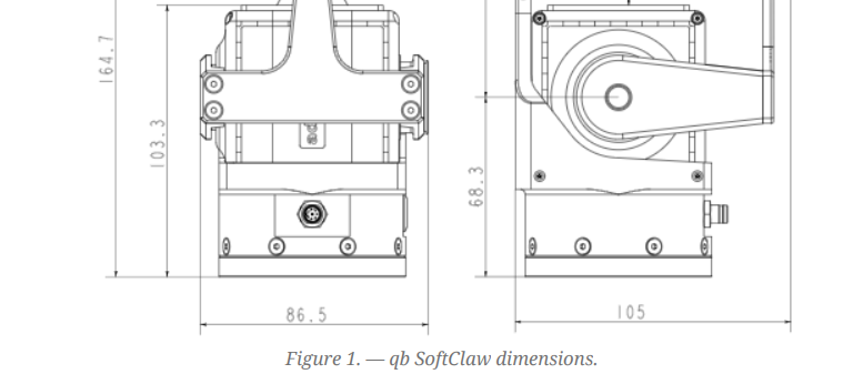
The figure below shows the overall dimensions of the QB SoftClaw; distances and tolerances in the drawing are noted in millimeters [mm] and degrees [°].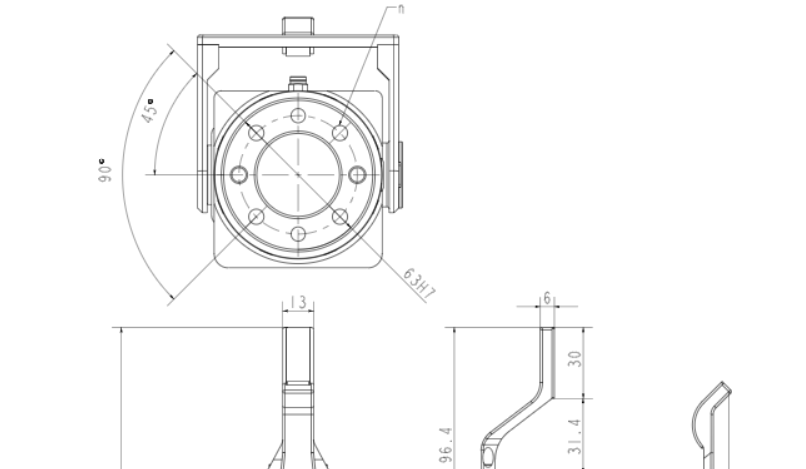
Center of Mass
The following table also gives the position of the Center of Mass of the SoftClaw and defines its Coordinate System, as depicted in the following schemes.
Center of Mass, OT, is evaluated with respect. ΣM, considering the device mounted with its fixed finger facing the ground, cf. the figures below.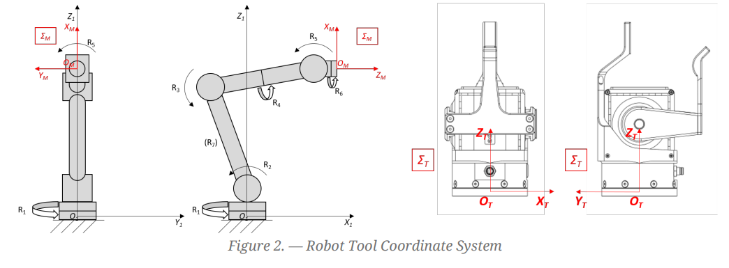
On the left, it is represented the mechanical interface coordinate system ΣM (OM; XM, YM, ZM) of an articulated robot is represented, as defined by ISO 9787:2013. In particular, the center of the coordinate system, OM, is on the interface surface of the robot tool flange, and the ZM axis is coincident with the tool flange axis of symmetry. Ri is the i-th revolute joint of the robot, and (O1; X1, Y1, Z1) is the base coordinate system of the robot.
On the right, there is the Tool Coordinate System, ΣT (OT; XT, YT, ZT), of the qb SoftClaw, and the center, OT, coincides with the center of mass of the device, and its position is defined by the distance from OM. The ZT axis is normal to the palm, outgoing positive, and the YT axis follows the proximal-distal direction and orientation.
Mechanical characteristics
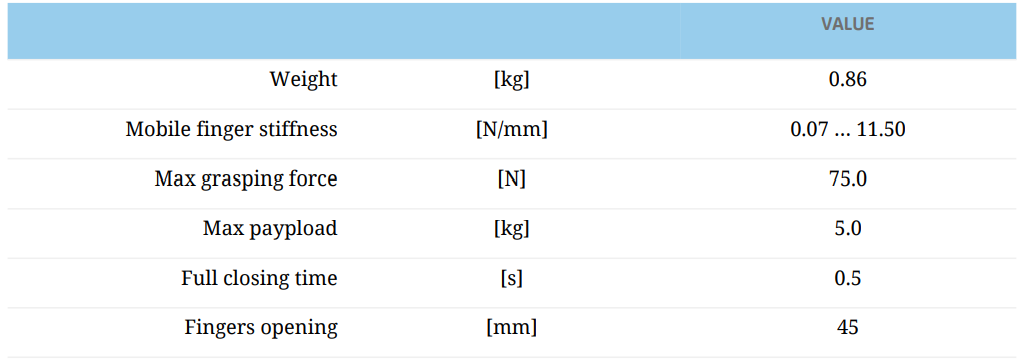
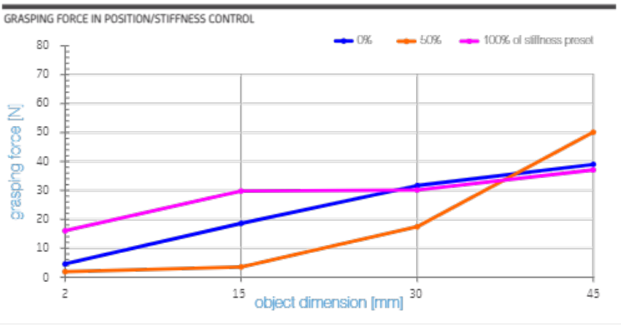
Look at the graph for details. The grasping force in the graph refers to the component along the line joining the centers of the two pads, so it depends on the size of the object. The obtained force also depends on control: DEFLECTION on the left and POSITION/STIFFNESS on the right.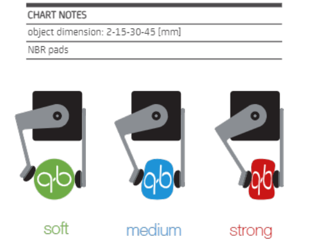

Electrical characteristics

Tool connector pinout
On the QB SoftClaw flange, there is a Phoenix Contact 8-position M8 connector, A-coded, with gold-plated copper alloy contacts — Part Number: 14242321. The main cable of the QB SoftClaw is a Phoenix Contact 3m free cable end with an angled socket — Part Number: 14041922. The RS-485 protocol characteristics are as follows:
- 8-bit;
- no parity;
- 1 stop bit;
- no flow control;
- 2M baud rate.

Fingers exchange system
The fingers are provided with an easy setup system by simple screws and reference pins.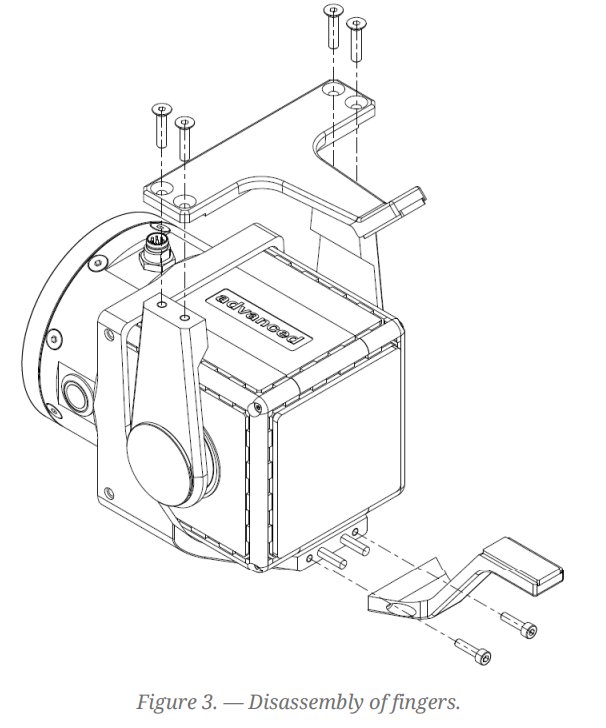
The fingers are designed to be easily replaceable to allow customization for special applications. The picture shows the standard version of fingers. For different or customized fingers, please ask for a quotation from Qbrobotics.
Description
General
The QB SoftClaw is a compact, light, and versatile Variable Stiffness Gripper. It’s able to grasp objects of the most disparate nature, exploiting the intrinsic mechanical intelligence of its variable stiffness system, without the use of any type of sensors on the contact surfaces or specific algorithms on the absorbed current by the motors.
The custom-made electronic board inside the QB SoftClaw is composed of a logic stage for communication and low-level computation, and a power stage for motion control. This, together with two DC motors and their encoders, establishes a simple position and current control feedback regulated by a properly tuned PID controller.
The QB SoftClaw does not use Common Industrial Protocols (CIP) or other industrial standards for I/O communication due to historical design and technical reasons. I/O data basically refers to measurements from the device, commands to the device, and parameters from/to the device. These are handled in a custom package format as follows.
- 2-byte — common preamble;
- 1-byte — target slave ID
- 1-byte — payload length
- n-byte — payload;
- 1-byte — checksum for communication integrity.
A custom-made single-master-multiple-slave (SMMS) serial communication protocol is implemented to:
- send commands to the connected devices;
- read measurements from the connected devices (motor position and/or current);
- get and set configuration parameters.
Control Modes
The QB SoftClaw can be controlled by two different modalities:
Position: It is the control mode that most closely approaches the operation of a classic gripper. In this modality, the user can control both position and stiffness. The first parameter is used to set the angular position of the qb SoftClaw movable finger; the second one allows the elasticity of the finger itself to be adjusted. Higher values of stiffness indicate greater stiffness of the gripper during the grasp; on the contrary, lower values allow soft grips.
Deflection: It is the control mode that allows the user to regulate the grip force during the grasp. This modality does not require any type of sensors on the contact surfaces or specific algorithms on the absorbed current by the motors, but exploits the mechanical intelligence of the qb SoftClaw. In this modality, the movable arm is controlled to close completely towards the fixed part for each commanded value. Small values allow gripping fragile and low-weight objects; on the contrary, higher values can be used for heavy and rigid objects.
Characteristics and key features
- Adaptive grasp;
- Variable Stiffness grasp;
- Interchangeable fingers;
- Plug and play with:
- Fanuc CRX series
- Universal Robots
- ROS packages and general C++ API available;
Grasp forces and payloads highly depend on object dimensions and approaching strategy (cf. Mechanical Characteristics (see Page 5)).
Standard customization
- Mechanical flange adapters for non-standard robot flanges;
Finger design for special applications.
Tool mounting
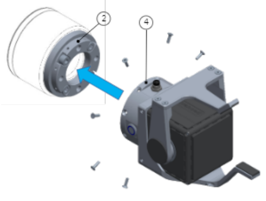
The QB SoftClaw Kit allows you to connect the device to your robot arm. The device can be mounted on any robot equipped with a mounting interface ISO 9409-1-50-4-M6. To assemble the device on the robot arm, please follow the instructions:
- Insert (1) into the 6 mm hole on the robot wrist, centering (2) on the wrist diameter 63 mm, taking care that the cylindrical pin (1) fits into one of the four d6 reamed through holes. Fasten (2) to the robot wrist by tightening the four screws (3). Max Tightening Torque, TTmax = 11.1 Nm.
 You need the 5 mm Allen wrench.
- Center (4) on the diameter 63 mm of (2), taking care that the plug fits into one of the four d6 mm through holes.

- Fix axially the device by tightening the 8 screws (5). Max Tightening Torque, TTmax = 2.1 Nm.
 You need the 2 mm Allen wrench.
Cable connections for FANUC CRX
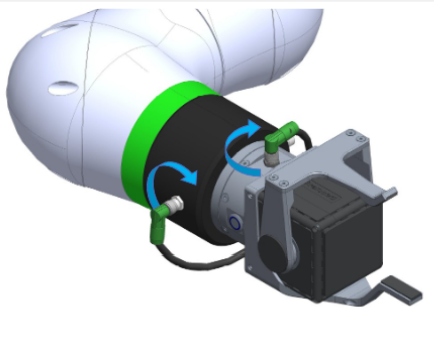
To control the device with a FANUC CRX robot, you have to connect the qb SoftClaw to the EE connector on the robot wrist.
INSTRUCTIONS
- Insert one of the two M8 connectors of (C0) into the receptacle on the SoftClaw wrist flange. Lock the M8 connector by manually tightening its threaded ring on the body of the receptacle (max tightening torque = 0.2 Nm).

- Do the same on the other M8 connector of (C0) with respect to the receptacle on the robot wrist flange. Lock the M8 connector by manually tightening its threaded ring on the body of the receptacle (max tightening torque = 0.2 Nm).

Copy of Cable connections for Universal Robots
To control the device with a FANUC CRX robot, you have to connect the qb SoftClaw to the EE connector on the robot wrist.
INSTRUCTIONS
- Insert one of the two M8 connectors of (C0) into the receptacle on the SoftClaw wrist flange. Lock the M8 connector by manually tightening its threaded ring on the body of the receptacle (max tightening torque = 0.2 Nm).

- Do the same on the other M8 connector of (C0) with respect to the receptacle on the robot wrist flange. Lock the M8 connector by manually tightening its threaded ring on the body of the receptacle (max tightening torque = 0.2 Nm).

Setting the Tool Center Point (TCP) and gripper weight
To use the QB SoftClaw correctly on the FANUC CRX robot, we recommend storing the Tool Center Point (TCP) and the gripper weight in the robot settings after the plugin installation (see Page 17).
TCP
- On the robot teach pendant, press MENU; expand the menu and go to Setup, and then press on Frames. Once
- The Frames page opens, select one of the displayed frames, and put the following values:
- Comment: qb SoftClaw
- [X, Y, Z] = [0, 0, 145]
- [W, P, R] = [90, 0, 0]

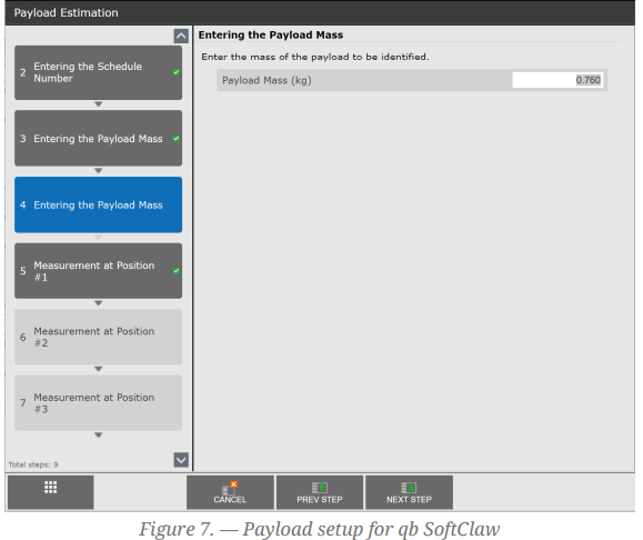
Weight
- On the robot teach pendant, press MENU;
- Press on Setup, and then press on UTool Payload Setup.
- Follow the individual steps of the setup process, and when the “Entering the Payload Mass” section is opened, enter the value 0.76 (Kg).
19 — MOUNTING AND WIRING
8 FAQ and troubleshooting
For any issue not listed below, please contact our support team.
8.1 The device is wired, but the blue LED on the device’s wrist is off
8.1.1 Problem
The device is connected and powered, but the blue LED on the device’s wrist is off, and the device doesn’t work, or the device suddenly stopped working, and the blue LED on the wrist turned off.
8.1.2 Solution
The self-resetting fuse in the device may have tripped. The first steps to try to solve the issue are the following:
- Switch off the device’s power supply and wait a few minutes before switching it on again.
- Check whether the wiring is correct, cf. cable connections (see Page 13).
If these steps do not solve the problem — i.e., the device still does not connect to the robot system — please raise a support request with at least the following details at our help desk portal:
- The device serial number;
- The type of control system (ROS, C++ API, GUI, etc.);
- The robot system type and software version;
- The power supply configuration.
- Any additional info regarding what you were doing before the first failure?
8.2 Error/warning codes on Fanuc CRX Robots
8.2.1 PLUG-001 The device is not active
The motor devices are not active. Go to the PLUGINS menu and press the Start button in the Activate qbrobotics device section. If the activation was successful, the status LED will become green.
8.2.2 PLUG-001 Param not retrieved or incorrect data type
The parameters were not retrieved when the block was executed in the timeline, or the data type is not compatible. Check whether the values entered are correct.
8.2.3 PLUG-001 Device not started. Use the activation tab.
The device was not enabled from the PLUGINS menu. Go to the PLUGINS menu and press the Start button in the Activate qbrobotics device section. If the activation was successful, the status LED will become green.
8.2.4 PLUG-001 Device not recognized.
The connected device is not compatible with this version of the qbrobotics plugin. Turn off the robot controller and connect a qbrobotics end-effector.
8.2.5 PLUG-001 Unsupported qbdevice for this application.
You are trying to control a QB SoftClaw from a QB SoftHand block. Use a QB SoftClaw block.
8.2.6 PLUG-001 Cannot retrieve DEVICE\_TYPE.
The device is not recognized. If a qbrobotics device is connected, go to the PLUGINS menu and press the Stop and then Start buttons in the Activate qbrobotics device section.
For More Manuals By qbrobotics, Visit ManualsLibraryy.
qbrobotics Fanuc CRX Robot SoftHand-FAQs
Q1. What are common problems with FANUC robots?
Common issues include electrical failures such as short circuits or power surges, which may affect motor performance. Regular maintenance reduces these risks.
Q2. How are FANUC robots controlled?
FANUC robots can be programmed using the teach pendant (a handheld device) or through a computer with FANUC’s proprietary programming languages.
Q3. How many joints does a FANUC robot have?
Most FANUC robots come with 6 joints (axes), providing six degrees of freedom for full-range motion. Some models may include more.
Q4. How do you manually move a FANUC robot?
Robots can be manually moved using the teach pendant in T1 or T2 mode, allowing operators to safely test or adjust movements.
Q5. How can you increase FANUC robot speed?
Use the teach pendant: open the program, navigate to the motion line, adjust the speed unit, and confirm the change.
Q6. What are the four basic robot configurations?
The main configurations are Cartesian, articulated, cylindrical, and spherical. These form the base for most industrial robot designs.
Q7. What is the difference between T1 and T2 modes in a FANUC robot?
T1 mode allows teaching at slow speed for safety, while T2 (if available) enables higher-speed testing during programming.
Q8. Which programming languages are used in FANUC robots?
FANUC robots use Karel (a Pascal-like advanced language) and TP (Teach Pendant language) for programming tasks.
Q9. What software is commonly used with FANUC robots?
ROBOGUIDE is FANUC’s official offline programming and simulation software, allowing 3D modeling without a physical setup.

