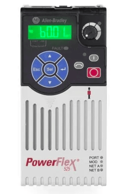
Allen-Bradley PowerFlex 525 Adjustable Frequency AC Drive
Overview
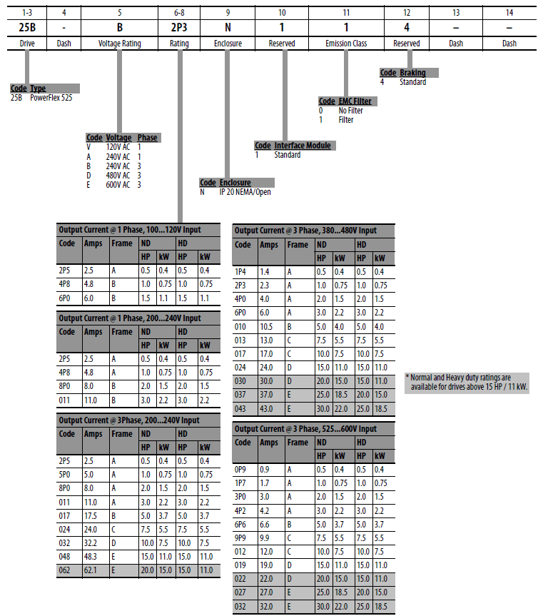
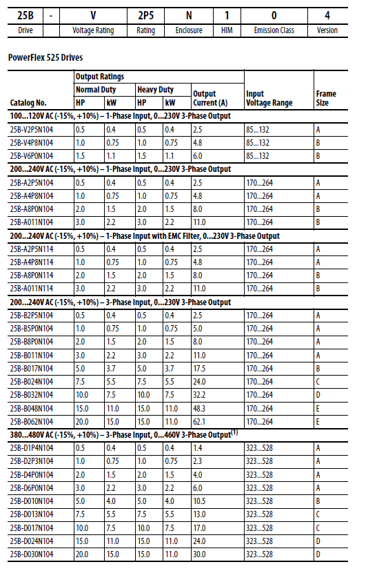
Catalog Number Explanation
Start-Up
Prepare for Drive Start-Up
Before Applying Power to the Drive
- Confirm that all inputs are connected to the correct terminals and are secure.
- Verify that AC line power at the disconnect device is within the rated value of the drive.
- Verify that any digital control power is 24 volts.
- Verify that the Sink (SNK)/Source (SRC) jumper is set to match your control wiring scheme. See the Control I/O Wiring Block Diagram on page 32 for location
- IMPORTANT The default control scheme is Source (SRC). The Stop terminal is jumpered to allow starting from the keypad or comms. If the control scheme is changed to Sink (SNK), the jumper must be removed from I/O Terminals 01 and 11 and installed between I/O Terminals 01 and 04.
- Verify that the Stop input is present or the drive will not start.
- IMPORTANT If I/O Terminal 01 is used as a stop input, the jumper between I/O Terminals 01 and 11 must be removed.
- Applying Power to the Drive
- Apply AC power and control voltages to the drive.
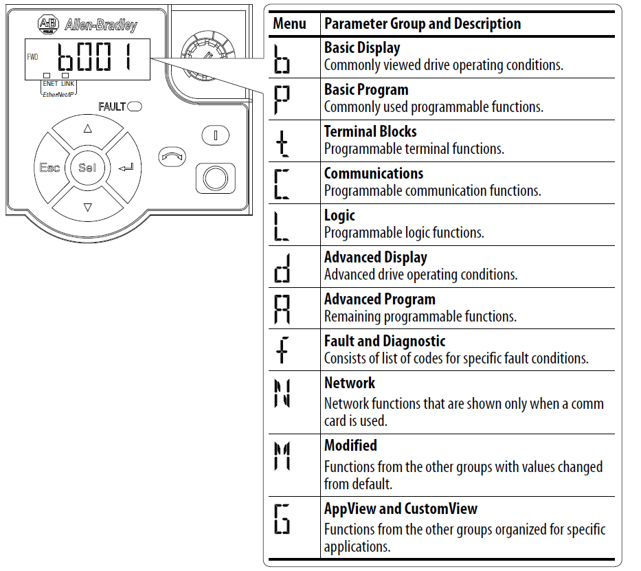
Display and Control Keys
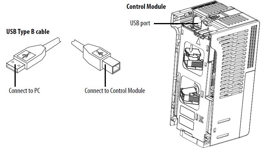
USB
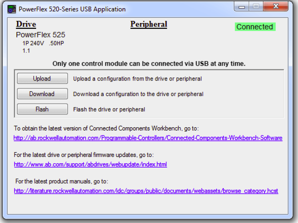
- The PowerFlex 525 drive has a USB port that connects to a PC for the purpose of upgrading drive firmware or uploading/downloading a parameter configuration. You do not need to power up the control module. Simply connect the PowerFlex 525 drive to your PC with a USB Type B cable, and you will benefit from MainsFree™ programming.
Connecting PowerFlex 525 to a PC
When connected, the drive appears on the PC and contains two files:
- GUIDE.PDF
- This file contains links to relevant product documentation and software downloads.
 PF52XUSB.EXE
- This file is an application to flash upgrade firmware or upload/download a parameter configuration. It is not possible to delete these files or add more to the drive
- Double-click on the PF52XUSB.EXE file to launch the USB utility application. The main menu is displayed. Follow the program instructions to upgrade the
firmware or upload/download configuration data
- IMPORTANT Make sure your PC is powered by an AC power outlet or has a fully charged battery before starting any operation. This prevents the operation from terminating before completion due to insufficient power.
Programming and Parameters
- This chapter provides a complete listing and description of the PowerFlex 525 parameters. Parameters are programmed (viewed/edited) using either the drive’s built-in keypad, RSLogix 5000 version 17.0 or greater, Logix Designer version 21.0 or greater, or Connected Components Workbench version 3.0 or greater software. The Connected Components Workbench software can be used offline (through USB) to upload parameter configurations to the drive or online
(through an Ethernet connection).
About Parameters
To configure a drive to operate in a specific way, drive parameters may have to be set. Three types of parameters exist:
- ENUM
- ENUM parameters allow a selection from 2 or more items. Each item is represented by a number.
- Numeric Parameters
- These parameters have a single numerical value (0.1V).
- Bit Parameters
- Bit parameters have five individual digits associated with features or conditions. If the digit is 0, the feature is off or the condition is false. If the digit is 1, the feature is on or the condition is true.
Parameter Groups
- For an alphabetical listing of parameters, see Parameter Cross Reference by Name on page 128
Network Parameter Group
- This group contains parameters for the network option card that is installed. Refer to the network option card’s user manual for more information on the
available parameters.
Modified Parameter Group
- This group contains parameters that have their values changed from the factory default. When a parameter has its default value change
 d, it is automatically added to this group. When a parameter has its value changed back to the factory default, it is automatically removed from this group.
Specifications
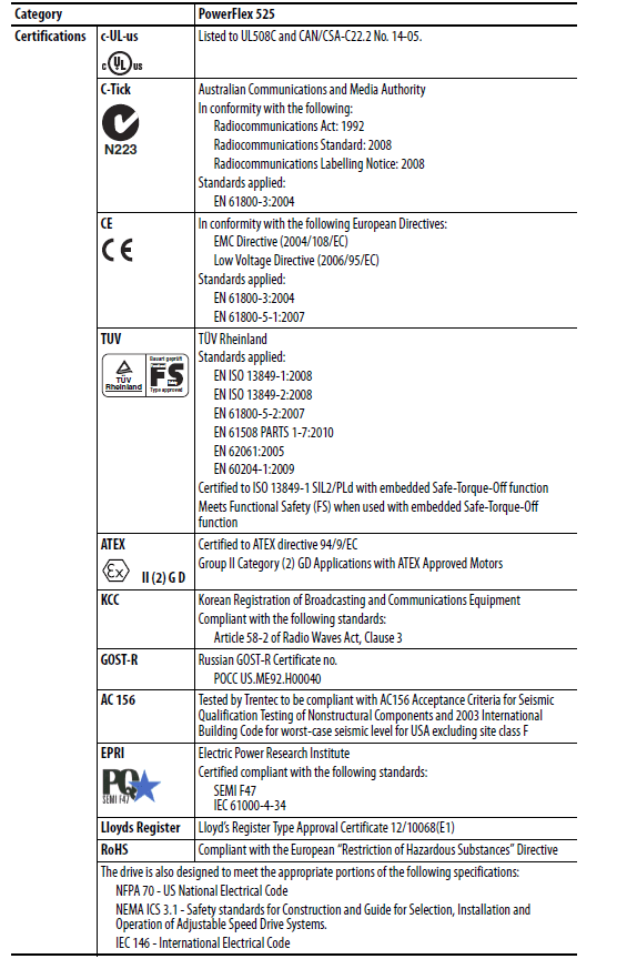
Product Selection
Catalog Number Description
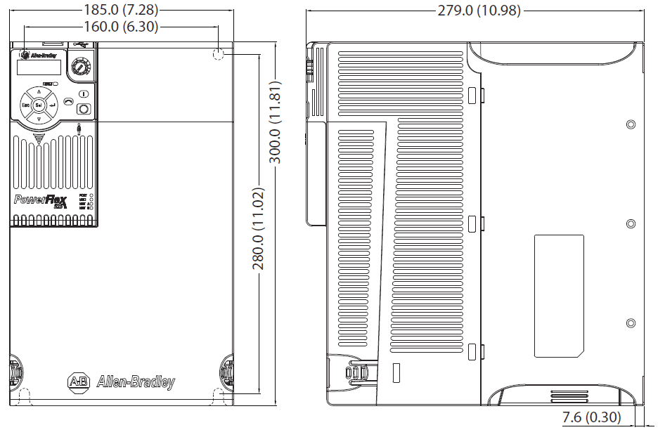
Product Dimensions
IP 20/Open Type – Frame A
Dimensions are in millimeters and (inches)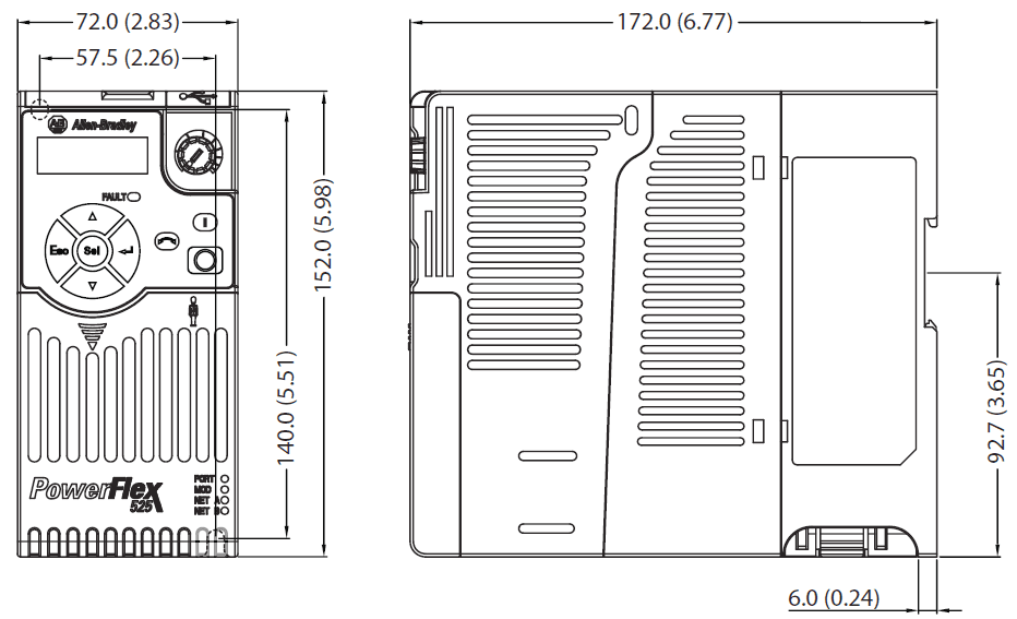
IP 20/Open Type – Frame B
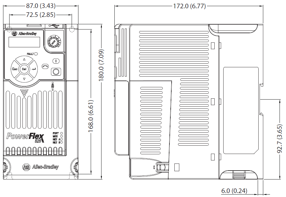
IP 20/Open Type – Frame C
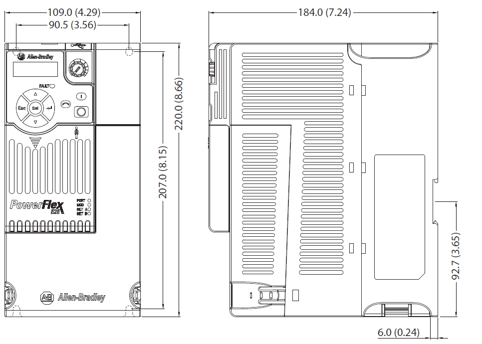
IP 20/Open Type – Frame D
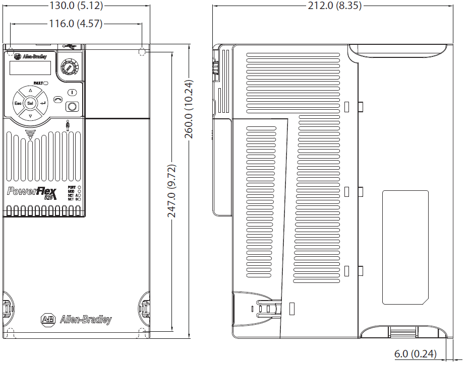
IP 20/Open Type – Frame E
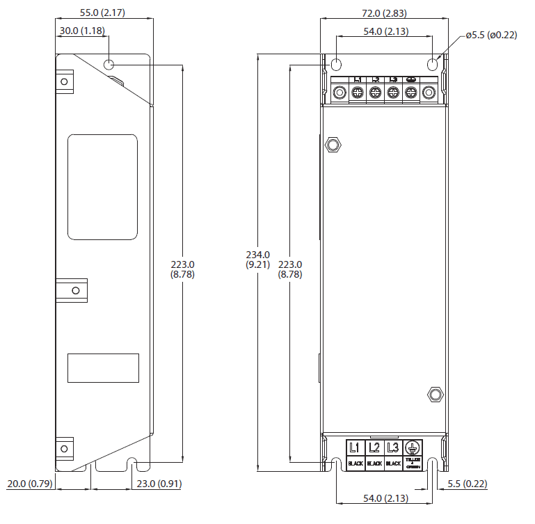
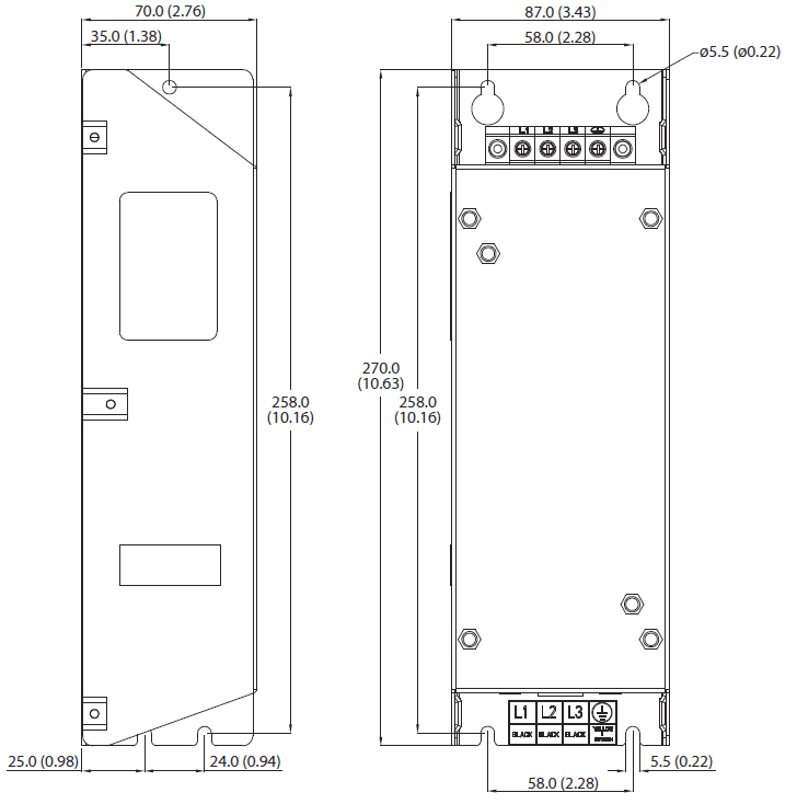
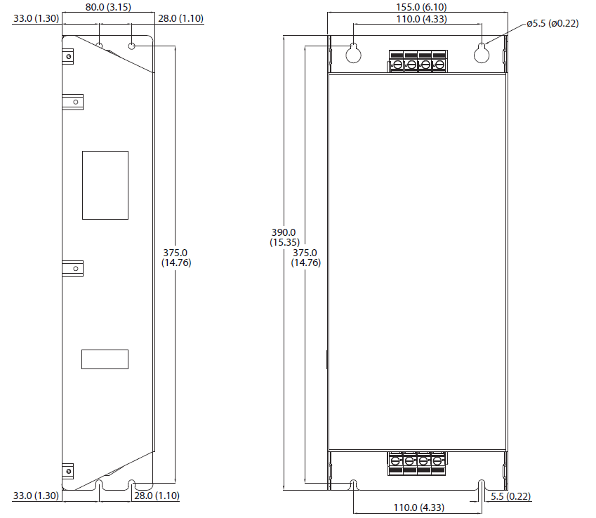
EMC Line Filter – Frame A
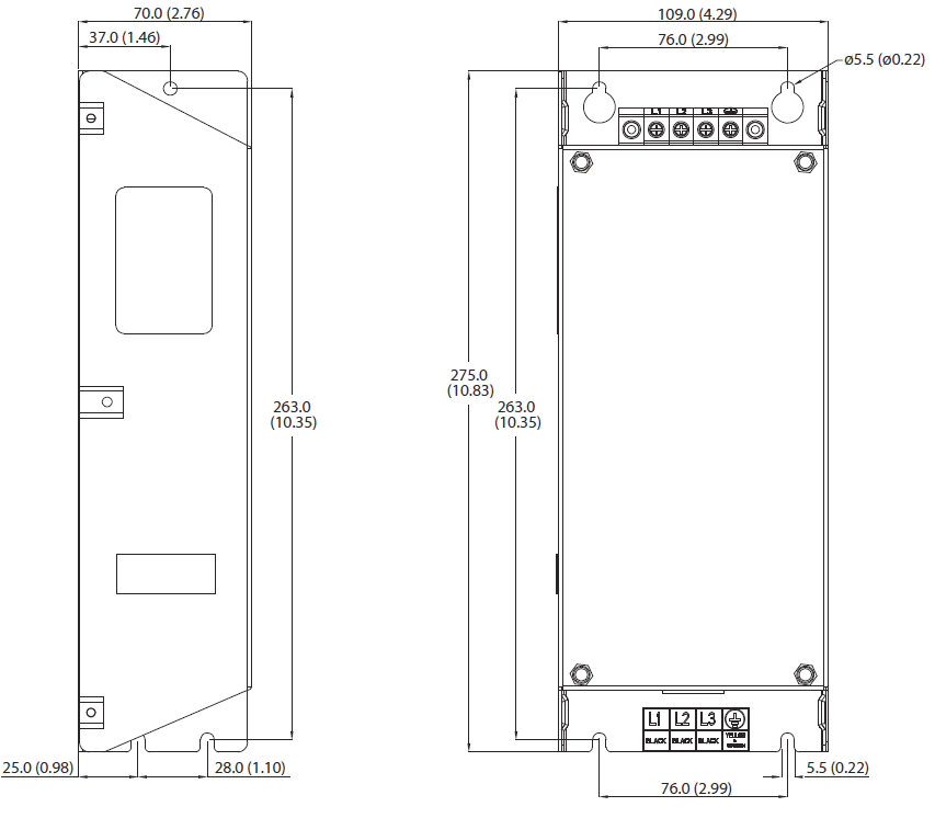
- Dimensions are in millimeters and (inches)
- The filter can be mounted onto the back of the drive

EMC Line Filter – Frame B
EMC Line Filter – Frame C
EMC Line Filter – Frame D
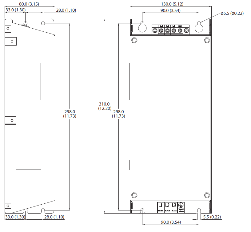
EMC Line Filter – Frame D
EtherNet/IP
- This section contains only basic information to setup an EtherNet/IP connection with your PowerFlex 525 drive. For comprehensive information about
EtherNet/IP (single and dual port) and how to use it, refer to “PowerFlex 525 Embedded EtherNet/IP Adapter”, publication 520COM-UM001.
Establishing A Connection With EtherNet/IP
There are two methods for configuring the embedded EtherNet/IP adapterIP address:
- BootP Server – Use BootP if you prefer to control the IP addresses of devices using a server. The IP address, subnet mask, and gateway addresses will then be provided by the BootP server. BootP is enabled by default.
- Adapter Parameters – Use adapter parameters when you want more flexibility in setting up the IP address, or need to communicate outside the control network using a gateway. The IP address, subnet mask, and gateway addresses will then come from the adapter parameters you set.
- IMPORTANT If you are setting your network addresses manually using parameters, you must set C128 [EN Addr Sel] to 1 “Parameters”.
- IMPORTANT Regardless of the method used to set the adapter IP address, each node on the EtherNet/IP network must have a unique IP address. To change an IP address, you must set the new value and then remove and reapply power to (or reset) the adapter.
Optional Accessories and Kits
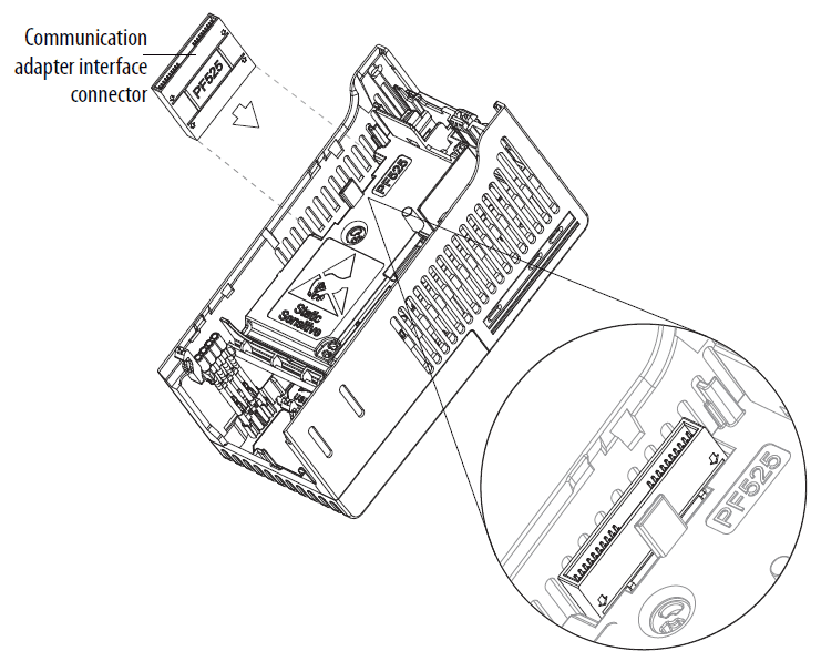
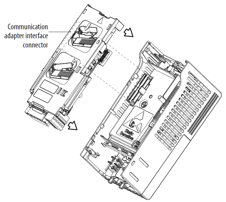
Installing a Communication Adapter
- Insert the communication adapter interface connector into the Control Module. Make sure the indicator line on the connector is aligned with the surface of the Control Module.

- Align the connectors on the communication adapter to the communication adapter interface connector, then push the back cover down.
- Press along the edges of the back cover until it snaps firmly into place.

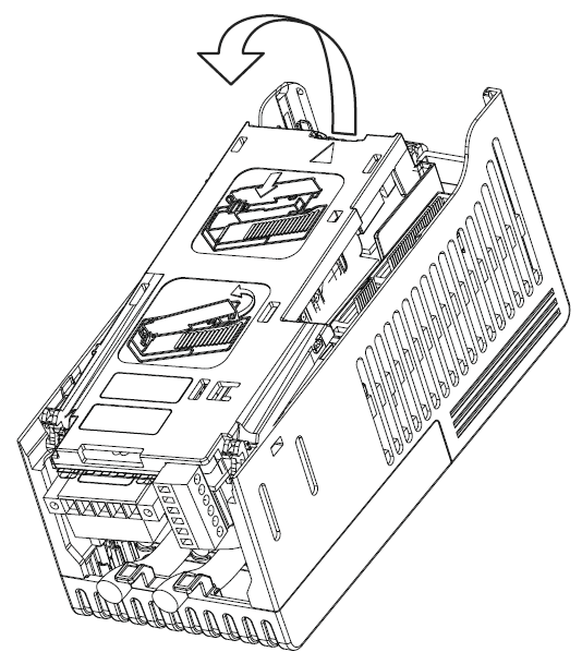
Removing a Communication Adapter
- Insert a finger into the slot at the top of the back cover. Lift to separate the back cover from the Control Module

RS485 (DSI) Protocol
- PowerFlex 525 drives support the RS485 (DSI) protocol to allow efficient operation with Rockwell Automation peripherals. In addition, some Modbus functions are supported to allow simple networking. PowerFlex 525 drives can be multi-dropped on an RS485 network using Modbus protocol in RTU mode.

Network Wiring
- Network wiring consists of a shielded 2-conductor cable that is daisy-chained from node to node.
Network Wiring Diagram
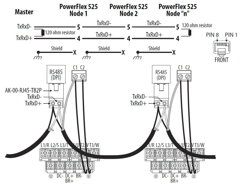
- IMPORTANT The shield is connected at ONLY ONE end of each cable segment.
- Only pins 4 and 5 on the RJ45 plug should be wired. The other pins on the PowerFlex 525 RJ45 socket must not be connected because they contain power,
etc. for other Rockwell Automation peripheral devices. - Wiring terminations on the master controller will vary depending on the master controller used and “TxRxD+” and “TxRxD-” are shown for illustration purposes only. Refer to the master controller’s user manual for network terminations. Note that there is no standard for the “+” and “-” wires, and consequently Modbus device manufacturers interpret them differently. If you have problems with initially establishing communications, try swapping the two
network wires at the master controller. Standard RS485 wiring practices apply.- Termination resistors need to be applied at each end of the network cable.
- RS485 repeaters may need to be used for long cable runs, or if greater than 32 nodes are needed on the network.
- Network wiring should be separated from power wires by at least 0.3 meters (1 foot).
- Network wiring should only cross power wires at a right angle.
- I/O Terminal C1 (RJ45 Shield) on the PowerFlex 525 drive must also be connected to PE ground (there are two PE terminals on the drive). See Control
- I/O Terminal Designations on page 33 for more information.
- I/O Terminal C2 (Comm Common) is internally tied to Network Common, and NOT to RJ45 Shield. Tying I/O Terminal C2 to PE ground may improve
noise immunity in some applications.
Control Diagrams
This chapter contains various diagrams on the PowerFlex 525 functions and behaviors.
Induction Motor Tuning Diagrams
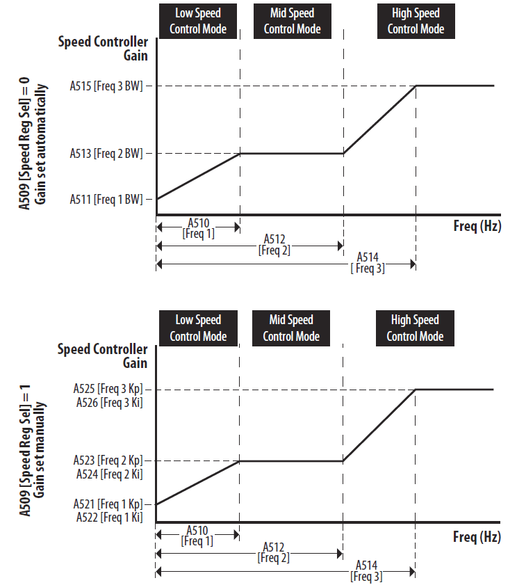
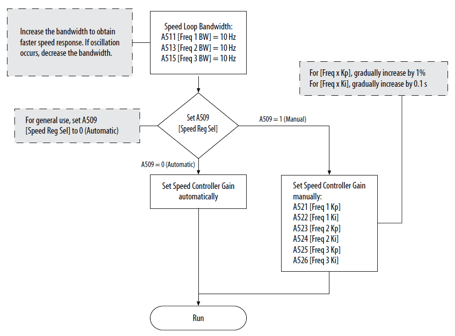
- Speed Reg Sel] Diagrams For Motor Tuning

Adjusting Speed Control Parameters
- These settings show how to adjust the speed control for motor tuning.

For more manuals by Allen-Bradley, visit ManualsLibraryy
Allen-Bradley PowerFlex 525 Adjustable Frequency AC Drive-FAQs
What is the maximum frequency setting for the PowerFlex 525?
The default maximum frequency for the PowerFlex 525 is 60 Hz. This setting can be adjusted based on specific requirements.
How can I change the motor rotation direction on the PowerFlex 525?
You can change the motor’s rotation direction in two ways:
Swap the motor leads.
Issue a reverse command when parameter 544 is set to false (this prevents reverse operation).
How do I control the frequency of a Variable Frequency Drive (VFD)?
VFD frequency can be controlled in two ways:
Networked control: This involves transmitting the desired speed using communication protocols like Modbus, Modbus/TCP, EtherNet/IP, or using a keypad with Display Serial Interface.
Hardwired control: This method directly controls the frequency using electrical connections.
What is the switching frequency of a VFD?
The switching frequency of a VFD typically ranges from 4 kHz to 16 kHz. This refers to how often the DC bus voltage is switched on and off during pulse width modulation (PWM) by Insulated Gate Bipolar Transistors (IGBT).
How do I clear a fault on the PowerFlex 525?
To clear a fault:
Press the Esc key to acknowledge the fault.
The fault information will be cleared, and you can regain control of the display and use the keypad.
Who converts DC to AC in a VFD?
An inverter is responsible for converting DC to AC in a VFD. It uses switches, diodes, and transistors to control the flow of current and produce a variable frequency AC output.
What is the minimum frequency at which a VFD can operate a motor?
The PowerFlex 525 can safely operate a motor at a minimum frequency of 0.01 Hz. However, the lowest speed depends on the motor’s characteristics and the specific application.
What are the three main components of a VFD?
A VFD has three primary components:
Rectifier: Converts AC to DC.
DC Bus: Stores and filters the DC power.
Inverter: Converts the DC back to variable frequency AC to control the motor speed.
Can a VFD create three-phase power?
Yes, many modern VFDs are capable of converting single-phase power to three-phase power, enabling the control of three-phase motors even when only single-phase input is available.
Can a VFD convert DC to AC?
Yes, a VFD can convert DC to AC. It uses an AC-to-DC converter, a DC bus for storing the rectified DC power, and an inverter to convert the DC back to AC with adjustable voltage and frequency.

 d, it is automatically added to this group. When a parameter has its value changed back to the factory default, it is automatically removed from this group.