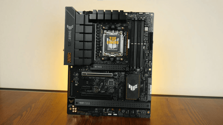
ASUS TUF GAMING B650-PLUS WIFI AMD B650 AM5 Ryzen Motherboard
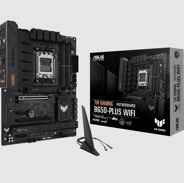
Package contents
Check your motherboard package for the following items.
- Motherboard
- 1 x TUF GAMING B650-PLUS WIFI motherboard
- Cables
- 2 x SATA 6Gb/s cables
- Miscellaneous
- 1 x ASUS Wi-Fi moving antennas
- 2 x Rubber Package(s) for M.2
- 1 x Screw package for M.2 SSD
- Documentation
- 1 x TUF Certification card
- 1 x User guide
Note: If any of the above items are damaged or missing, contact your retailer.
TUF GAMING B650-PLUS WIFI specifications summary
CPU
- AMD Socket AM5 for AMD Ryzen™ 7000 Series Desktop Processors*
* Refer to www.asus.com for the CPU support list.
Chipset
- AMD B650 Chipset
Memory
- 4 x DIMM slots, Max. 128GB, DDR5 ECC and Non-ECC, Unbuffered Memory*
- Dual Channel Memory Architecture
- Supports AMD Extended Profiles for Overclocking (EXPO™)
- OptiMem II
* Supported memory types, data rate (speed), and number of DRAM modules vary depending on the CPU and memory configuration, for more information please refer to CPU/Memory Support under the Support tab or visit https://www.asus.com/support/.
** Non-ECC, Un-buffered DDR5 Memory supports On-Die ECC function.
Graphics
- 1 x DisplayPort*
- 1 x HDMI™ port**
* Supports max. 8K@60Hz as specified in DisplayPort 1.4.
** Supports 4K@60Hz as specified in HDMI 2.1.
*** VGA resolution support depends on the processors’ or graphics cards’ resolution.
Expansion Slots
- AMD Ryzen™ 7000 Series Desktop Processors*
- 1 x PCIe 4.0/3.0 x16 slot
- AMD B650 Chipset
- 1 x PCIe 4.0/3.0 x16 slot (supports x4 mode)
- 2 x PCIe 4.0/3.0 x1 slots
* Please check the PCIe bifurcation table on the support site (https://www.asus.com/support/FAQ/1037507/).
Note: To ensure compatibility of the device installed, please refer to https://www.asus.com/support/ for the list of supported peripherals.
Storage
- Total supports 3 x M.2 slots and 4 x SATA 6Gb/s ports*
- AMD Ryzen™ 7000 Series Desktop Processors
- M.2_1 slot (Key M), type 2242/2260/2280 (supports PCIe 5.0 x4 mode)
- M.2_2 slot (Key M), type 2242/2260/2280/22110 (supports PCIe 4.0 x4 mode)
- AMD B650 Chipset
- M.2_3 slot (Key M), type 2242/2260/2280 (supports PCIe 4.0 x4 mode)** 4 x SATA 6Gb/s ports
* AMD RAIDXpert2 Technology supports both PCIe RAID 0/1/10 and SATA RAID 0/1/10.
** M.2_3 shares bandwidth with PCIEX16_2. PCIEX16_2 will be suspended once M.2_3 is populated.
Ethernet
- 1 x Realtek 2.5Gb Ethernet TUF LANGuard
Wireless & Bluetooth®
- Wi-Fi 6
- 2×2 Wi-Fi 6 (802.11 a/b/g/n/ac/ax)
- Supports 2.4/5GHz frequency band Bluetooth® v5.2*
* The Bluetooth version may vary; please refer to the Wi-Fi module manufacturer’s website for the latest specifications.
USB
- Rear USB (Total 8 ports)
- 1 x USB 3.2 Gen 2×2 port (1 x USB Type-C®)
- 3 x USB 3.2 Gen 2 ports (2 x Type-A +1 x USB Type-C® )
- 4 x USB 2.0 ports (4 x Type-A)
- Front USB (Total 7 ports)
- 1 x USB 3.2 Gen 1 connector (supports USB Type-C®)
- 1 x USB 3.2 Gen 1 header supports 2 additional USB 3.2 Gen 1 ports
- 2 x USB 2.0 headers support 4 additional USB 2.0 ports
Audio
- Realtek 7.1 Surround Sound High Definition Audio CODEC*
- Supports: Jack detection, Multi-streaming, Front Panel Jack-retasking
- Supports up to 24-bit/192kHz playback
- Audio Features
- Audio Shielding
- Premium audio capacitors
- Dedicated audio PCB layers
- Audio cover
- Unique de-pop circuit
* Due to limitations in HDA bandwidth, 32-bit/192 kHz is not supported for 7.1 Surround Sound audio.
** A chassis with an HD audio module in the front panel is required to support 7.1 Surround Sound audio output.
Back Panel I/O Ports
- 1 x USB 3.2 Gen 2×2 port (1 x USB Type-C®)
- 3 x USB 3.2 Gen 2 ports (2 x Type-A + 1 x USB Type-C®)
- 4 x USB 2.0 ports (2 x Type-A)
- 1 x DisplayPort
- 1 x HDMI™ port
- 1 x Wi-Fi Module
- 1 x Realtek 2.5Gb Ethernet port
- 5 x Audio jacks
- 1 x BIOS FlashBack™ button
Internal I/O Connectors
- Fan and cooling-related
- 1 x 4-pin CPU Fan header
- 1 x 4-pin CPU OPT Fan header
- 1 x 4-pin AIO Pump header
- 4 x 4-pin Chassis Fan headers
- Power related
- 1 x 24-pin Main Power connector
- 1 x 8-pin +12V Power connector
- 1 x 4-pin +12V Power connector
- Storage related
- 3 x M.2 slots (Key M)
- 4 x SATA 6Gb/s port
- USB
- 1 x USB 3.2 Gen 1 connector (supports USB Type-C®)
- 1 x USB 3.2 Gen 1 header supports 2 additional USB 3.2 Gen 1 ports
- 2 x USB 2.0 headers support 4 additional USB 2.0 ports
- Miscellaneous
- 3 x Addressable Gen 2 headers
- 1 x Aura RGB header
- 1 x Clear CMOS header
- 1 x COM Port header
- 1 x Front Panel Audio header (AAFP)
- 1 x 20-3-pin System Panel header with Chassis intrusion function
- 1 x Thunderbolt™ (USB4®) header
Special Features
- ASUS TUF PROTECTION
- DIGI+ VRM (- Digital power design with DrMOS)
- Enhanced DRAM Overcurrent Protection
- ESD Guards
- TUF LANGuard
- Overvoltage Protection
- SafeSlot+
- Stainless-Steel Back I/O
- ASUS Q-Design
- M.2 Q-Latch
- Q-DIMM
- Q-LED (CPU [red], DRAM [yellow], VGA [white], Boot Device [yellow green])
- Q-Slot
- ASUS Thermal Solution
- M.2 heatsink
- VRM heatsink design
- ASUS EZ DIY
- BIOS FlashBack™ button
- BIOS FlashBack™ LED
- ProCool
- Pre-mounted I/O shield
- SafeDIMM
- Aura Sync
- Aura RGB header
- Addressable Gen 2 headers
Software Features
ASUS Exclusive Software
- Armoury Crate
- Aura Creator
- Aura Sync
- Fan Xpert 4
- Power Saving
- Two-Way AI Noise Cancelation
- AI Suite 3
- TurboV EVO
- DIGI+ VRM
- PC Cleaner
- TUF GAMING CPU-Z
- DTS Audio Processing
- MyASUS
- Norton Anti-Virus software (Free Trial version)
- WinRAR
UEFI BIOS
- ASUS EZ DIY
- ASUS CrashFree BIOS 3
- ASUS EZ Flash 3
- ASUS UEFI BIOS EZ Mode
BIOS
- 256 Mb Flash ROM, UEFI AMI BIOS
Manageability
- WOL by PME, PXE
Operating System
- Windows® 11
- Windows® 10 64-bit
Form Factor
- ATX Form Factor 12 inch x 9.6 inch (30.5 cm x 24.4 cm)
Note:
- Specifications are subject to change without notice. Please refer to the ASUS website for the latest specifications.
- MyASUS offers a variety of support features such as helping to troubleshoot issues, optimizing product performance, integrating ASUS software, and recovery drive creation. Please scan the code for installation guide and FAQ.

- For more information on downloading and installing drivers and utilities for your motherboard, please scan the code below:

Product Introduction
Before you proceed
Take note of the following precautions before you install motherboard components or change any motherboard settings.
- Unplug the power cord from the wall socket before touching any component.
- Before handling components, use a grounded wrist strap or touch a safely grounded object or a metal object, such as the power supply case, to avoid damaging them due to static electricity.
- Hold components by the edges to avoid touching the ICs on them.
- Whenever you uninstall any component, place it on a grounded antistatic pad or in the bag that came with the component.
- Before you install or remove any component, ensure that the ATX power supply is switched off or the power cord is detached from the power supply. Failure to do so may cause severe damage to the motherboard, peripherals, or components.
Tips:
- The pin definitions in this chapter are for reference only. The pin names depend on the location of the header/jumper/connector.
- For more information on installing your motherboard, please scan the code below:

Motherboard overview
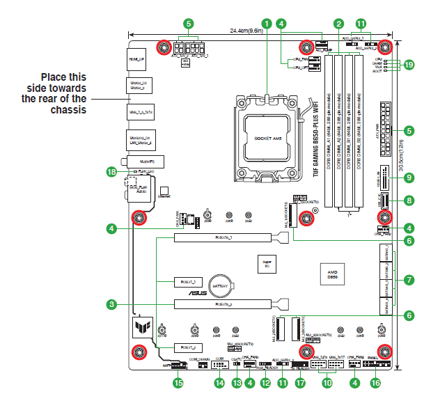
Unplug the power cord before installing or removing the motherboard. Failure to do so can cause you physical injury and damage motherboard components.
Layout contents
CPU socket
The motherboard comes with a Socket AM5 designed for AMD Ryzen™ 7000 Series Desktop Processors.
Note: For more details, refer to Central Processing Unit (CPU).
DDR5 DIMM slots
The motherboard comes with Dual Inline Memory Modules (DIMM) slots designed for DDR5 (Double Data Rate 5) memory modules.
Note:
For more details, refer to System memory.
Expansion slots
This motherboard supports two PCIe x16 graphics cards and two PCIe x1 network cards, SCSI cards and other cards that comply with the PCI Express specification.
Note:
- Additional PCIe bifurcation and M.2 settings for RAID function are also supported when a Hyper M.2 x16 series card is installed.
- For full details on the PCIe bifurcation, you may visit the support site at https://www.asus.com/support/FAQ/1037507/.
- The Hyper M.2 x16 series card is sold separately.
- Adjust the PCIe bifurcation under BIOS settings.
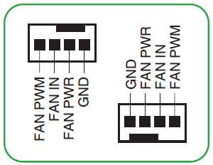
Fan headers
The Fan headers allow you to connect fans to cool the system.

Power connectors
- These Power connectors allow you to connect your motherboard to a power supply. The power supply plugs are designed to fit in only one orientation. Find the proper orientation and push down firmly until the power supply plugs are fully inserted.
- Ensure to connect the 8-pin power plug, or connect both the 8-pin and 4-pin power plugs.
- We recommend that you use a PSU with a higher power output when configuring a system with more power-consuming devices. The system may become unstable or may not boot up if the power is inadequate.
- If you want to use two high-end PCI Express x16 cards, use a PSU with 1000W power or above to ensure system stability.
M.2 slots (Key M)
The M.2 slots allow you to install M.2 devices such as M.2 SSD modules.
• AMD Ryzen™ 7000 Series Desktop Processors:
– M.2_1 slot supports PCIe 5.0 x4 mode M Key design, and type 2242/2260/2280 storage devices.
– M.2_2 slot supports PCIe 4.0 x4 mode M key design and type 2242/2260/2280/22110 storage devices.
• AMD B650 Chipset:
– M.2_3 slot supports PCIe 4.0 x4 mode M key design and type 2242/2260/2280 storage devices.
SATA 6Gb/s ports
The SATA 6Gb/s ports allow you to connect SATA devices such as optical disc drives and hard disk drives via SATA cables.
USB 3.2 Gen 1 Type-C® connector
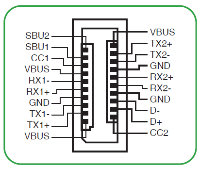
The USB 3.2 Gen 1 connector (USB Type-C®) allows you to connect a USB 3.2 Gen 1 module for an additional USB 3.2 Gen 1 Type-C® port. The connector provides a data transfer speed of up to 5 Gb/s. The USB 3.2 Gen 1 Type-C® module is purchased separately.
Note: The USB 3.2 Gen 1 Type-C® module is purchased separately.
USB 3.2 Gen 1 header
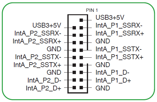
The USB 3.2 Gen 1 header allows you to connect a USB 3.2 Gen 1 module for additional USB 3.2 Gen 1 ports. The USB 3.2 Gen 1 header provides data transfer speeds of up to 5 Gb/s.
Note: The USB 3.2 Gen 1 module is purchased separately.
USB 2.0 headers
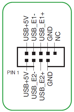
The USB 2.0 headers allow you to connect a USB module for additional USB 2.0 ports. The USB 2.0 headers provide data transfer speeds of up to 480 Mb/s.
Warning: DO NOT connect a 1394 cable to the USB connectors. Doing so will damage the motherboard!
Note: The USB 2.0 module is purchased separately.
Addressable Gen 2 headers
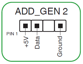
The Addressable Gen 2 headers allow you to connect individually addressable RGB WS2812B LED strips or WS2812 B-based LED strips.
Tip: The Addressable Gen 2 headers support WS2812B addressable RGB LED strips (5V/Data/ Ground), with a maximum power rating of 3A (5V), and the addressable headers on this board can handle a combined maximum of 500 LEDs.
Warning: Before you install or remove any component, ensure that the power supply is switched off or the power cord is detached from the power supply. Failure to do so may cause severe damage to the motherboard, peripherals, or components.
Note:
- Actual lighting and color will vary with the LED strip.
- If your LED strip does not light up, check if the addressable RGB LED strip is connected in the correct orientation, and the 5V connector is aligned with the 5V header on the motherboard.
- The addressable RGB LED strip will only light up when the system is powered on.
- The addressable RGB LED strip is purchased separately.
Aura RGB header
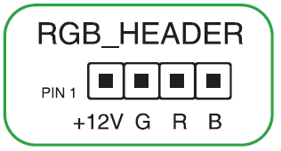
The RGB header allows you to connect RGB LED strips.
Tip: The RGB headers support 5050 RGB multi-color LED strips (12V/G/R/B), with a maximum power rating of 3A (12V), and no longer than 3m.
Warning: Before you install or remove any component, ensure that the ATX power supply is switched off or the power cord is detached from the power supply. Failure to do so may cause severe damage to the motherboard, peripherals, or components.
Note:
- Actual lighting and color will vary with the LED strip.
- If your LED strip does not light up, check if the RGB LED extension cable and the RGB LED strip are connected in the correct orientation, and the 12V connector is aligned with the 12V header on the motherboard.
- The LED strip will only light up when the system is powered on.
- The LED strip is purchased separately.
Clear CMOS header
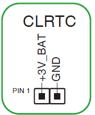
The Clear CMOS header allows you to clear the Real Time Clock (RTC) RAM in the CMOS, which contains the date, time, system passwords, and system setup parameters.
To erase the RTC RAM:
- Turn OFF the computer and unplug the power cord.
- Short-circuit pin 1-2 with a metal object or jumper cap for about 5-10 seconds.
- Plug the power cord and turn ON the computer.
- Hold down the <Del> key during the boot process and enter BIOS setup to re-enter data.
Warning: DO NOT short-circuit the pins except when clearing the RTC RAM. Short-circuiting or placing a jumper cap will cause system boot failure!
Note: If the steps above do not help, remove the onboard button cell battery and short the two pins again to clear the CMOS RTC RAM data. After clearing the CMOS, reinstall the button cell battery.
COM Port header
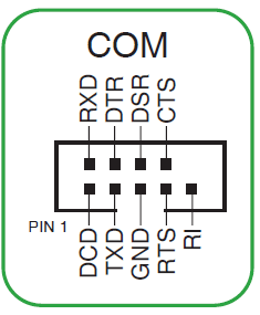
The COM (Serial) Port header allows you to connect a COM port module. Connect the COM port module cable to this header, then install the module in a slot opening on the system chassis.
Front panel audio header
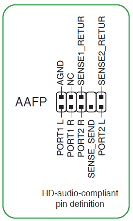
This header is for a chassis-mounted front panel audio I/O module that supports HD Audio. Connect one end of the front panel audio I/O module cable to this header.
Tip: We recommend that you connect a high-definition front panel audio module to this header to avail of the motherboard’s high-definition audio capability.
System Panel header
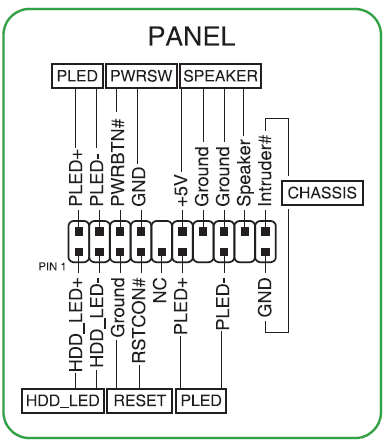
This header supports several chassis-mounted functions.
- System Power LED header (PLED)
The 2-pin and/or 3-1 pin headers allow you to connect the System Power LED. The System Power LED lights up when the system is connected to a power source, or when you turn on the system power, and blinks when the system is in sleep mode. - Storage Device Activity LED header (HDD_LED)
The 2-pin header allows you to connect the Storage Device Activity LED. The Storage Device Activity LED lights up or blinks when data is read from or written to the storage device or storage device add-on card. - System Warning Speaker header (SPEAKER)
The 4-pin header allows you to connect the chassis-mounted system warning speaker. The speaker allows you to hear system beeps and warnings. - Power Button/Soft-off Button header (PWRSW)
The 3-1 pin header allows you to connect the system power button. Press the power button to power up the system, or put the system into sleep or soft-off mode (depending on the operating system settings). - Reset button header (RESET)
The 2-pin header allows you to connect the chassis-mounted reset button. Press the reset button to reboot the system. - Chassis intrusion header (CHASSIS)
The 2-pin header allows you to connect the chassis-mounted intrusion detection sensor or switch. The chassis intrusion sensor or switch sends a high-level signal to the header when a chassis component.
Thunderbolt™ (USB4®) header
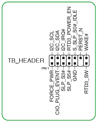
The Thunderbolt™ (USB4®) header allows you to connect an add-on Thunderbolt™ I/O card that supports Intel®’s Thunderbolt™ Technology, allowing you to connect Thunderbolt™-enabled devices to form a daisy chain configuration.
Note:
- The add-on Thunderbolt™ I/O card and Thunderbolt™ cables are purchased separately.
- Please visit the official website of your purchased Thunderbolt card for more details on compatibility.
Tip:
The Thunderbolt™ card can only be used when installed in the PCIEX16_2 slot. Ensure to install your Thunderbolt™ card in the PCIEX16_2 slot.
BIOS FlashBackTM LED

The BIOS FlashBack™ LED lights up or blinks to indicate the status of the BIOS FlashBack™.
Tip: Scan the code for more information on the BIOS FlashBackTM function.
Q-LEDs
The Q-LEDs check key components (CPU, DRAM, VGA, and booting devices) during the motherboard booting process. If an error is found, the critical component’s LED stays lit up until the problem is solved.
Note: The Q-LEDs provide the most probable cause of an error code as a starting point for troubleshooting. The actual cause may vary from case to case.
FCC Compliance Information
- Responsible Party: Asus Computer International
- Address: 48720 Kato Rd., Fremont, CA 94538, USA
- Phone / Fax No: (510)739-3777 / (510)608-4555
This device complies with part 15 of the FCC Rules. Operation is subject to the following two conditions: (1) This device may not cause harmful interference, and (2) this device must accept any interference received, including interference that may cause undesired operation. This equipment has been tested and found to comply with the limits for a Class B digital device, under part 15 of the FCC Rules.
These limits are designed to provide reasonable protection against harmful interference in a residential installation. This equipment generates, uses, and can radiate radio frequency energy and, if not installed and used according to the instructions, may cause harmful interference to radio communications.
However, there is no guarantee that interference will not occur in a particular installation. If this equipment does cause harmful interference to radio or television reception, which can be determined by turning the equipment off and on, the user is encouraged to try to correct the interference by one or more of the following measures:
- Reorient or relocate the receiving antenna.
- Increase the separation between the equipment and receiver.
- Connect the equipment to an outlet on a circuit different from that to which the receiver is connected.
- Consult the dealer or an experienced radio/TV technician for help.
RF exposure warning
This equipment must be installed and operated according to the provided instructions, and the antenna(s) used for this transmitter must be installed to provide a separation distance of at least 20 cm from all persons and must not be co-located or operating in conjunction with any other antenna or transmitter. End-users and installers must be provided with antenna installation instructions and transmitter operating conditions for satisfying RF exposure compliance.
HDMI Trademark Notice
The terms HDMI, HDMI High-Definition Multimedia Interface, HDMI Trade dress, and the HDMI Logo are trademarks or registered trademarks of HDMI Licensing Administrator, Inc.

Compliance Statement of Innovation, Science and Economic Development Canada (ISED)
This device complies with Innovation, Science and Economic Development Canada licence-exempt RSS standard(s). Operation is subject to the following two conditions: (1) this device may not cause interference, and (2) this device must accept any interference, including interference that may cause undesired operation of the device.
Operation in the band 5150–5250 MHz is only for indoor use to reduce the potential for harmful interference to co-channel mobile satellite systems.
CAN ICES-003(B)/NMB-003(B)
Safety Precautions
Accessories that came with this product have been designed and verified for the use in connection with this product. Never use accessories for other products to prevent the risk of electric shock or fire.
Simplified EU Declaration of Conformity
ASUSTek Computer Inc. hereby declares that this device complies with the essential requirements and other relevant provisions of Directive 2014/53/EU. Full text of the EU declaration of conformity is available at https://www.asus.com/support/.
Warranty
ASUS Guarantee Information
- ASUS offers a voluntary manufacturer’s Commercial Guarantee.
- ASUS reserves the right to interpret the provisions of the ASUS Commercial Guarantee.
- This ASUS Commercial Guarantee is provided independently and in addition to the statutory Legal Guarantee and in no way affects or limits the rights under the Legal Guarantee.
For all the guarantee information, please visit https://www.asus.com/support.
Service and Support
Visit our multi-language website at https://www.asus.com/support.
For more manuals by ASUS, visit ManualsLibrary
ASUS TUF GAMING B650-PLUS WIFI AMD B650 AM5 Ryzen Motherboard- FAQs
Does the ASUS TUF B650-PLUS WIFI motherboard support Bluetooth?
Yes, it features Bluetooth 5.2 support, allowing seamless connectivity for wireless devices such as headsets, keyboards, and game controllers.
What RAM is best for the ASUS TUF B650-PLUS WIFI motherboard?
The G.SKILL Trident Z5 NEO RGB DDR5 memory is highly recommended for this motherboard, offering excellent performance and compatibility.
Is the B650 chipset good for gaming and productivity?
Yes, the B650 chipset is a great value option that supports AM5 processors like the Ryzen 7000 series. It’s ideal for users who want strong performance without the higher cost of the X670 chipset.
Is the ASUS TUF GAMING motherboard waterproof?
While the motherboard itself is not waterproof, ASUS TUF Gaming A1 SSD external enclosures are designed to be dust-proof, waterproof, and drop-resistant.
Does the B650 motherboard include Bluetooth by default?
Yes, select models like the ASUS TUF GAMING B650-PLUS WIFI come with Bluetooth 5.2, though this can vary by manufacturer and model.
Which ASUS motherboards come with built-in Wi-Fi?
Models such as the ASUS PRIME B650-PLUS WIFI and ASUS TUF GAMING B650-PLUS WIFI include Wi-Fi 6E and Bluetooth, along with extensive connectivity options.
What is the maximum supported RAM speed for ASUS TUF motherboards?
The ASUS TUF GAMING B550M-PLUS supports up to 128GB of DDR4 RAM, with speeds up to 4400 MHz when overclocked. The B650 model supports DDR5 memory at even higher speeds depending on the RAM kit used.
How many M.2 slots does the ASUS TUF B650-PLUS WIFI have?
It comes with three M.2 slots, allowing you to install multiple high-speed SSDs for better performance and storage capacity.

